EP2310543B2 - Procédé de trempe d'au moins une piste de roulement d'un anneau d'appui pour un palier à roulements à grande dimension - Google Patents
Procédé de trempe d'au moins une piste de roulement d'un anneau d'appui pour un palier à roulements à grande dimension Download PDFInfo
- Publication number
- EP2310543B2 EP2310543B2 EP09776843.6A EP09776843A EP2310543B2 EP 2310543 B2 EP2310543 B2 EP 2310543B2 EP 09776843 A EP09776843 A EP 09776843A EP 2310543 B2 EP2310543 B2 EP 2310543B2
- Authority
- EP
- European Patent Office
- Prior art keywords
- inductors
- heating
- raceway
- main
- zone
- Prior art date
- Legal status (The legal status is an assumption and is not a legal conclusion. Google has not performed a legal analysis and makes no representation as to the accuracy of the status listed.)
- Active
Links
Images


Classifications
-
- C—CHEMISTRY; METALLURGY
- C21—METALLURGY OF IRON
- C21D—MODIFYING THE PHYSICAL STRUCTURE OF FERROUS METALS; GENERAL DEVICES FOR HEAT TREATMENT OF FERROUS OR NON-FERROUS METALS OR ALLOYS; MAKING METAL MALLEABLE, e.g. BY DECARBURISATION OR TEMPERING
- C21D9/00—Heat treatment, e.g. annealing, hardening, quenching or tempering, adapted for particular articles; Furnaces therefor
- C21D9/40—Heat treatment, e.g. annealing, hardening, quenching or tempering, adapted for particular articles; Furnaces therefor for rings; for bearing races
-
- C—CHEMISTRY; METALLURGY
- C21—METALLURGY OF IRON
- C21D—MODIFYING THE PHYSICAL STRUCTURE OF FERROUS METALS; GENERAL DEVICES FOR HEAT TREATMENT OF FERROUS OR NON-FERROUS METALS OR ALLOYS; MAKING METAL MALLEABLE, e.g. BY DECARBURISATION OR TEMPERING
- C21D1/00—General methods or devices for heat treatment, e.g. annealing, hardening, quenching or tempering
- C21D1/06—Surface hardening
- C21D1/09—Surface hardening by direct application of electrical or wave energy; by particle radiation
- C21D1/10—Surface hardening by direct application of electrical or wave energy; by particle radiation by electric induction
-
- C—CHEMISTRY; METALLURGY
- C21—METALLURGY OF IRON
- C21D—MODIFYING THE PHYSICAL STRUCTURE OF FERROUS METALS; GENERAL DEVICES FOR HEAT TREATMENT OF FERROUS OR NON-FERROUS METALS OR ALLOYS; MAKING METAL MALLEABLE, e.g. BY DECARBURISATION OR TEMPERING
- C21D1/00—General methods or devices for heat treatment, e.g. annealing, hardening, quenching or tempering
- C21D1/34—Methods of heating
- C21D1/42—Induction heating
-
- F—MECHANICAL ENGINEERING; LIGHTING; HEATING; WEAPONS; BLASTING
- F16—ENGINEERING ELEMENTS AND UNITS; GENERAL MEASURES FOR PRODUCING AND MAINTAINING EFFECTIVE FUNCTIONING OF MACHINES OR INSTALLATIONS; THERMAL INSULATION IN GENERAL
- F16C—SHAFTS; FLEXIBLE SHAFTS; ELEMENTS OR CRANKSHAFT MECHANISMS; ROTARY BODIES OTHER THAN GEARING ELEMENTS; BEARINGS
- F16C33/00—Parts of bearings; Special methods for making bearings or parts thereof
- F16C33/30—Parts of ball or roller bearings
- F16C33/58—Raceways; Race rings
- F16C33/64—Special methods of manufacture
-
- F—MECHANICAL ENGINEERING; LIGHTING; HEATING; WEAPONS; BLASTING
- F16—ENGINEERING ELEMENTS AND UNITS; GENERAL MEASURES FOR PRODUCING AND MAINTAINING EFFECTIVE FUNCTIONING OF MACHINES OR INSTALLATIONS; THERMAL INSULATION IN GENERAL
- F16C—SHAFTS; FLEXIBLE SHAFTS; ELEMENTS OR CRANKSHAFT MECHANISMS; ROTARY BODIES OTHER THAN GEARING ELEMENTS; BEARINGS
- F16C2300/00—Application independent of particular apparatuses
- F16C2300/10—Application independent of particular apparatuses related to size
- F16C2300/14—Large applications, e.g. bearings having an inner diameter exceeding 500 mm
-
- Y—GENERAL TAGGING OF NEW TECHNOLOGICAL DEVELOPMENTS; GENERAL TAGGING OF CROSS-SECTIONAL TECHNOLOGIES SPANNING OVER SEVERAL SECTIONS OF THE IPC; TECHNICAL SUBJECTS COVERED BY FORMER USPC CROSS-REFERENCE ART COLLECTIONS [XRACs] AND DIGESTS
- Y02—TECHNOLOGIES OR APPLICATIONS FOR MITIGATION OR ADAPTATION AGAINST CLIMATE CHANGE
- Y02P—CLIMATE CHANGE MITIGATION TECHNOLOGIES IN THE PRODUCTION OR PROCESSING OF GOODS
- Y02P10/00—Technologies related to metal processing
- Y02P10/25—Process efficiency
Definitions
- the invention relates to a method according to the preamble of claim 1 for hardening at least one raceway of a bearing ring for a large rolling bearing.
- GB-PS 735 378 a procedure is known ( GB-PS 735 378 ), which uses two counter-rotating inductors whose heating conductors are provided with associated sections that overlap once the inductors are positioned in the initial or final zone. This may reduce gaps between the inductors, but cannot completely eliminate them, as mutual contact or excessive proximity of the heating conductors must be prevented.
- the technical problem of the invention is to improve the method of the type described at the outset in such a way that the raceway can be provided with a consistently high hardness without gaps, i.e. also in the initial and/or final zones to be heated together, while avoiding the disadvantages mentioned.
- the method according to the invention is based on the knowledge that soft, unhardened segments in the raceway of the bearing ring can be avoided by applying a heat treatment agent at least during the preheating of the End zone, selected properties (or states) of the auxiliary inductor can be controlled and thereby specifically changed or adjusted.
- selected properties or states
- Preferred properties in this Examples of factors that are relevant are the frequency and phase position of the currents flowing through the heating conductors or the location of an auxiliary inductor, as explained in more detail below.
- Fig. 1 shows a bearing ring 1 with at least one raceway 2 to be hardened, here axial, and two inductors of conventional design, hereinafter referred to as main inductors 3 and 4, arranged in different positions along the raceway 2.
- Each main inductor 3, 4 contains a heating loop 5, which is essentially formed from two heating conductors 7 arranged radially to a central axis 6 of the bearing ring 1 and electrically connected to one another.
- the heating loops 5 of the two main inductors 3 and 4 are arranged parallel to and at a short distance from the raceway 2 and also in the area of a hatched, common heating or starting zone 8.
- the heating loops 5 are here, viewed in the circumferential direction of the bearing ring 1, at the smallest possible distance from one another. In this position, the heating of an edge layer of the raceway 2 is started by switching on the main inductors 3, 4. In order to ensure that the entire initial zone 8 is heated to the desired hardening temperature up to a preselected depth of the surface layer of the raceway 2, the bearing ring 1 and/or the main inductors 3, 4 can be set in a pendulum movement in the circumferential direction.
- the raceway 2 is initially heated in intermediate zones 9 until the main inductors 3 and 4 reach another common heating zone, hereinafter referred to as the end zone 10, in which they meet again and are arranged with the smallest possible distance, as in the initial zone 8, in order to heat the end zone 10 together.
- showers are used, which serve to spray the heated zones with a cooling liquid. Fig. 1 but are not shown to avoid confusion.
- showers are preferably connected to the main inductors 3 and 4 to form a jointly movable unit in the circumferential direction and are particularly advantageously pivotally mounted so that they can be positioned as required so that the cooling liquid is directed in the desired direction and sequence to all heated zones.
- the main inductors 3 and 4 after the end zone 10 has been sufficiently heated, can be removed perpendicularly to the track 2 and transferred to an inoperative position, which in Fig. 1 indicated by reference numerals 3a, 4a. This allows the nozzles to be pivoted so that the track 2 can subsequently also be quenched in the area of the end zone 10.
- auxiliary inductor 11 is additionally arranged where the end zone 10 is located.
- This auxiliary inductor 11 can be advanced in the direction of a double arrow 12 towards the track or retracted therefrom and has at least one heating loop 14, which is preferably designed analogously to the heating loops 5 of the main inductors 3, 4 and can extend essentially over the entire length of the end zone 10, measured in the circumferential direction.
- the auxiliary inductor 11 is advanced in the direction of the track 2 and activated in order to preheat it in the area of the end zone 10.
- the auxiliary inductor 11 is retracted again so that the remaining heating of the end zone 10 can be taken over by the main inductors 3, 4.
- Fig. 3 shows a first exemplary embodiment of such an additional measure. It schematically shows a section of the bearing ring 1 with a conically extending raceway 2a, to which the two main inductors 3, 4 and the auxiliary inductor 11 are assigned in such a way that the heating loops 5, 14 are essentially parallel to the raceway 2a.
- Straight arrows indicate the directions of movement of the main inductors 3, 4 during their counter-rotating movement.
- arrows 15 indicate that the auxiliary inductor 11 in the working position is provided with at least one additional degree of freedom, which in this case enables movement of the auxiliary inductor 11 about an axis of rotation 16 rotating parallel to its central axis and preferably arranged perpendicular to the raceway 2a.
- auxiliary inductor 11 once it has reached its working position just above the track 2a, is set into a circular, oval, rectangular, or square movement around the axis of rotation 16 and simultaneously activated, then instead of a preheating zone that only has an outer contour determined by the position of the heating conductors of the heating loop 14, a preheating zone 17 is formed that has a more circular or rectangular contour and in any case extends over a larger area than would be possible without movement of the auxiliary inductor 11. In addition, a much more uniform heating is achieved in the preheating zone 17 than when using a rigidly arranged auxiliary inductor 11 because the heating loop 14 or its heating conductor 7 constantly change their position relative to the track 2a during the circular movement.
- the described rotational movement about a spatially fixed axis of rotation 16 can be modified by subjecting the axis of rotation 16 to an additional pendulum movement during the preheating phase.
- the auxiliary inductor 11 is attached to a cross table 13 which is movable in x, y, z directions.
- auxiliary inductor 11 which types of movement are favorable for the auxiliary inductor 11 and how many degrees of freedom are required for its movement can be determined on a case-by-case basis through experiments.
- the movements of the auxiliary inductor 11 and the opposing movements of the main inductors 3, 4 should be coordinated so that, after removing the auxiliary inductor 11 and reuniting the main inductors 3, 4, the preheating zone 17 is brought to the desired hardening temperature even in the gaps that would otherwise lead to soft spots.
- Another possible measure to equalise the heating of the track 2 in the area of the common start and/or end zone 8, 10 consists in operating the main and auxiliary inductors 3, 4, and 11 at different frequencies. In this case, it is advisable to feed the main inductors 3 and 4 with heating currents of different frequencies, especially when they approach the common heating zone 8, 10 or are already at their smallest possible distance therefrom. This makes it possible to avoid such irregularities in the heating zones 8, 10 that arise due to their otherwise identical and symmetrical design and mode of operation.
- the setting of different frequencies can be provided regardless of whether only the two main inductors 3 and 4 ( Fig. 1 ) or additionally the auxiliary inductor 11 ( Fig. 2 ) are present.
- the type of preheating and thus the contour of the preheating zone 17 can be influenced by selecting the frequency.
- Fig. 4 An example is shown in which the inductors 3, 4, and 11 are supplied with voltages U1, U2, and U3 of different frequencies, resulting in correspondingly different heating currents. It would also be possible to change the frequencies of the heating currents stepwise or continuously during the heating of critical zones.
- a third embodiment of the invention, currently considered the best, is shown in Fig. 5 and 6 shown. Fig.
- FIG. 5 shows a rough schematic of the position of the main inductors 3 and 4 as well as the auxiliary inductor 11 shortly before the time at which the auxiliary inductor 11 is raised in the direction of arrow 12 to create space for the joining of the main inductors 3, 4.
- Reference numeral 18 here represents the supply lines to the heating loops 5 and 14 or to the heating conductors 7 arranged perpendicular to the plane of the drawing, wherein the supply lines 18 of each inductor 3, 4 and 11 are fed from a separate AC voltage source with the voltages UI, U2 and U3.
- the invention provides an additional measure for equalizing the heating of the initial and/or final zones by controlling the properties of the inductors 3, 4 and 11 so that the heating currents flowing through the heating conductors 7 have a defined phase position.
- the phase position is selected in particular so that heating conductors 7 of adjacent or approaching inductors facing each other are always flowed through by heating current in the same direction.
- the opposing heating conductors 7a of the inductors 3 and 11 are both flowed through by heating current in one direction and the opposing heating conductors 7b of the inductors 11 and 4 are both flowed through in the opposite direction.
- the heating of the track 2 is based on the fact that the heating conductors 7a, 7b induce eddy currents in it that are opposite to the heating currents that generate them, the eddy currents can, if the phase position is not controlled, flow in opposite directions in the transition areas between two inductors 3 and 11 or 11 and 4 and cancel or neutralize each other, thereby reducing the heat input. If, on the other hand, the phases of the heating currents are adjusted accordingly, Fig. 5 controlled in such a way that the opposing heating conductors 7a and 7b are traversed by heating current in the same direction in pairs, this ensures that the induced eddy currents add up to a maximum and thus cause sufficient heating even in the critical gaps. This is Fig.
- FIG. 5 schematically indicated for zones 19 and 20, in which the direction of the eddy currents is also indicated by dots and crosses.
- Fig. 5 that the common heating zones each have a section 19a, 20a bridging the spaces between the inductors 3, 11 and 11, 4 respectively.
- the phase position can be controlled regardless of whether only the two main inductors 3, 4 or also the auxiliary inductor 11 are used. What is important in this case is not the total number of inductors present, but rather the phase position of their heating currents, particularly when two inductors approach each other in the area of the start and/or end zones 8, 10, 19, 20 or are at their smallest possible distance from each other.
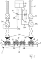
- Fig. 6 An example of how to adjust the phase position is shown in Fig. 6 shown using the two inductors 3 and 4.
- the voltage sources for the voltages UI1 U2 ( Fig. 5 ) each contain a rectifier 22 connected to the usual power grid 21, to which an inverter 23a, 23b is connected, the outputs of which are connected to a primary coil of a transformer 24.
- a secondary coil of the transformers 24 is connected to the supply lines 18 (see also Fig. 5 ) of the associated heating loops 5.
- Dots, crosses and arrows are analogous to Fig. 5 the directions of the currents flowing through the heating conductors of the heating loops 5 at a preselected time are shown.
- the application of the rectifiers 22 and the inverters 23a, 23b serves the purpose of increasing the frequency of the currents supplied to the transformers 24 to values of, for example, 4 kHz to 10 kHz.
- This frequency is preferably adjustable in order to Fig. 4 different frequencies.
- the frequencies of the output voltages of the inverters 23a, 23b are preferably set to the same values.
- Each additional input of the inverters 23a, 23b is connected to a control unit 26 via a line 25a, 25b.
- Control signals 27, 28 are transmitted to the inverters 23a, 23b via the lines 25a, 25b, which control the firing times of their power transistors, thyristors, or the like, and thus their phase positions.
- Fig. 6 shows, for example, that the control signals 27 supplied to the inverter 23a each transmit a positive pulse 27a at intervals of 360° and thus determine the phase position of the output voltage of the inverter 23a.
- the control signals 28 supplied to the inverter 23b each have a positive pulse 28a exactly between two pulses 27a, which determines the phase position of the output voltage of the inverter 23b such that its phase is shifted by exactly 180° relative to the output voltage of the inverter 23a.
- a correct connection of the inverters 23a, 23b to the transformers 24 then results in the Fig. 5 and 6 indicated current flows.
- FIG. 6 The schematically indicated magnetic fields 29 generating the eddy currents lead to eddy currents in a common heating zone 30 at the time when the two inductors 3, 4 have approached their closest possible distance (reference symbols 3b, 4b). These eddy currents are directed in the same direction in the critical area between the two inductors 3b, 4b and can therefore at best reinforce each other but not cancel each other out. This, in turn, allows for additional uniformity of heating in zone 30.
- the described adjustment or control of the phase position can be performed regardless of whether the two main inductors 3, 4 or a main inductor 3, 4 and the auxiliary inductor 11 are approaching or opposing each other. Furthermore, it is clear that the described adjustment of the phase position can also be performed and maintained across the entire range of motion of the inductors 3, 4, and 11.
Landscapes
- Engineering & Computer Science (AREA)
- Chemical & Material Sciences (AREA)
- Mechanical Engineering (AREA)
- Materials Engineering (AREA)
- Crystallography & Structural Chemistry (AREA)
- Thermal Sciences (AREA)
- Physics & Mathematics (AREA)
- Metallurgy (AREA)
- Organic Chemistry (AREA)
- General Engineering & Computer Science (AREA)
- Manufacturing & Machinery (AREA)
- General Induction Heating (AREA)
- Heat Treatment Of Articles (AREA)
Claims (7)
- Procédé de trempe d'au moins une piste de roulement (2, 2a) d'un anneau de palier (1) pour un palier à roulements de grande dimension, comprenant les étapes de procédé suivantes :- la disposition d'au moins deux inducteurs principaux (3, 4) dans la région d'une zone de début commune (8) de la piste de roulement (2, 2a) et le chauffage de la piste de roulement (2, 2a) dans la région de la zone de début (8) au moyen des inducteurs principaux (3, 4) ;- le déplacement des inducteurs principaux (3, 4) dans des directions opposées le long de la piste de roulement (2, 2a) et le chauffage de la piste de roulement (2, 2a) au moyen des inducteurs (3, 4) dans des zones intermédiaires successives (9) parcourues par ceux-ci jusqu'à atteindre et chauffer une zone où deux inducteurs principaux (3, 4) déplacés en opposition se réunissent pour constituer une zone de fin commune (10) ;- la mise en œuvre d'un inducteur auxiliaire supplémentaire (11) dans la région de la zone de fin (10), le préchauffage de la piste de roulement (2, 2a) au moyen de l'inducteur auxiliaire (11) dans la région de la zone de fin (10) et le retrait de l'inducteur auxiliaire (11) de la zone de fin (10) avant que les deux inducteurs principaux (3, 4) se rapprochent directement de la zone de fin (10) ;- le refroidissement brusque de la piste de roulement (2, 2a) dans la région des zones de début, intermédiaire et de fin (8, 9, 10) chauffées au moyen des inducteurs (3, 4, 11) et- la régularisation du chauffage de la piste de roulement (2, 2a) dans la région de la zone de début et/ou de fin commune (8, 10) en prenant au moins une mesure supplémentaire,caractérisé en ce que- la mesure supplémentaire prévoit une commande ou un réglage mécanique d'au moins une propriété sélectionnée de l'inducteur auxiliaire (11) au moins pendant le préchauffage de la zone de fin (10),- dans lequel ladite au moins une propriété sélectionnée est la position spatiale de l'inducteur auxiliaire (11) et la mesure supplémentaire prévoit un mouvement de l'inducteur auxiliaire (11) avec au moins un degré de liberté supplémentaire pendant le préchauffage, selon lequel le mouvement de l'inducteur auxiliaire (11) s'effectue de manière circulaire, elliptique, rectangulaire ou quadratique, dans lequel les conducteurs chauffants (7) de l'inducteur auxiliaire (11) sont toujours disposés parallèlement à la piste de roulement (2, 2a).
- Procédé selon la revendication 1, caractérisé en ce que le mouvement de l'inducteur auxiliaire (11) inclut au moins un mouvement de rotation parallèle à la piste de roulement (2, 2a).
- Procédé selon la revendication 1 ou 2, caractérisé en ce que la propriété sélectionnée est la fréquence des courants de chauffage parcourant les inducteurs principaux et/ou auxiliaires (3, 4, 11) et en ce que la mesure supplémentaire prévoit un fonctionnement des inducteurs principaux et auxiliaires (3, 4, 11) à des fréquences différentes et éventuellement variables.
- Procédé selon la revendication 3, caractérisé en ce que les inducteurs principaux (3, 4) fonctionnent à des fréquences différentes au moins lorsqu'ils se rapprochent de la zone de début et/ou de fin (8, 10) ou lorsqu'ils sont disposés dans celle-ci.
- Procédé selon l'une des revendications 1 à 4, caractérisé en ce que la propriété sélectionnée est la position de phase des courants de chauffage parcourant les inducteurs principaux et auxiliaires (3, 4, 11) et en ce que la mesure supplémentaire prévoit un réglage présélectionné des phases desdits courants de chauffage.
- Procédé selon la revendication 5, caractérisé en ce que la position de phase des courants de chauffage, en particulier lorsque deux inducteurs principaux (3, 4) ou un inducteur principal et l'inducteur auxiliaire (3, 11 ; 4, 11) se rapprochent de la zone de fin (19, 20, 30), est réglée de manière à ce que les conducteurs chauffants (7a, 7b) des inducteurs (3, 4, 11) se faisant mutuellement face soient parcourus par des courants de chauffage circulant dans la même direction.
- Procédé selon la revendication 5 ou 6, caractérisé en ce que le réglage de la position de phase s'effectue en commandant les tensions de sortie (U1 à U3) des sources de tension au moyen desquelles les courants de chauffage sont générés.
Applications Claiming Priority (2)
| Application Number | Priority Date | Filing Date | Title |
|---|---|---|---|
| DE102008033735A DE102008033735A1 (de) | 2008-07-18 | 2008-07-18 | Verfahren zum Härten wenigstens einer Laufbahn eines Lagerrings für ein Großwälzlager |
| PCT/EP2009/004611 WO2010006689A1 (fr) | 2008-07-18 | 2009-06-26 | Procédé de trempe d'au moins une piste de roulement d'un anneau d'appui pour un palier à roulements à grande dimension |
Publications (3)
| Publication Number | Publication Date |
|---|---|
| EP2310543A1 EP2310543A1 (fr) | 2011-04-20 |
| EP2310543B1 EP2310543B1 (fr) | 2019-08-07 |
| EP2310543B2 true EP2310543B2 (fr) | 2025-05-28 |
Family
ID=41127547
Family Applications (1)
| Application Number | Title | Priority Date | Filing Date |
|---|---|---|---|
| EP09776843.6A Active EP2310543B2 (fr) | 2008-07-18 | 2009-06-26 | Procédé de trempe d'au moins une piste de roulement d'un anneau d'appui pour un palier à roulements à grande dimension |
Country Status (4)
| Country | Link |
|---|---|
| EP (1) | EP2310543B2 (fr) |
| DE (1) | DE102008033735A1 (fr) |
| ES (1) | ES2753433T3 (fr) |
| WO (1) | WO2010006689A1 (fr) |
Families Citing this family (13)
| Publication number | Priority date | Publication date | Assignee | Title |
|---|---|---|---|---|
| IT1398579B1 (it) | 2010-03-05 | 2013-03-01 | Saet Spa | Metodo e dispositivo per tempra ad induzione localizzata di componenti meccanici circolari di grandi dimensioni, in particolare ralle per cuscinetti di rotolamento |
| PL2559319T3 (pl) | 2010-04-13 | 2017-11-30 | Inductoheat, Inc. | Indukcyjna obróbka cieplna pierścieniowego przedmiotu obrabianego |
| DE102012101309A1 (de) | 2012-02-17 | 2013-08-22 | Thyssenkrupp Rothe Erde Gmbh | Verfahren zum induktiven Randschichthärten einer Ringfläche |
| DE102012101304A1 (de) | 2012-02-17 | 2013-08-22 | Thyssenkrupp Rothe Erde Gmbh | Verfahren und Anordnung zum Vorschub-Randschichthärten |
| DE102013101057B4 (de) | 2013-02-01 | 2017-01-26 | Thyssenkrupp Rothe Erde Gmbh | Flächiger Induktor |
| DE102013208478B4 (de) | 2013-05-08 | 2017-04-06 | Aktiebolaget Skf | Verfahren zum Randschichthärten eines metallischen Bauteils |
| EP3119161B1 (fr) | 2014-03-11 | 2020-03-11 | THK Co., Ltd. | Dispositif de traitement thermique et méthode de traitement thermique |
| DE102016114895A1 (de) * | 2016-08-11 | 2018-02-15 | Thyssenkrupp Ag | Verfahren zum Härten einer Wälzkörperlaufbahn eines Wälzlagerrings und Wälzlagerring |
| DE102017218645A1 (de) * | 2017-10-19 | 2019-04-25 | Zf Friedrichshafen Ag | Induktor und Verfahren zum induktiven Erwärmen eines Gelenks für ein Fahrzeug |
| DE102018207904A1 (de) | 2018-05-18 | 2019-11-21 | Aktiebolaget Skf | Induktionshärteanlage zum induktiven Härten eines Großwälzlagerrings |
| DE102020103299A1 (de) | 2020-02-10 | 2021-08-12 | Sms Elotherm Gmbh | Verfahren zum induktiven Randschichthärten |
| WO2021165532A1 (fr) | 2020-02-20 | 2021-08-26 | Sms Elotherm Gmbh | Procédé de durcissement de surface par induction |
| DE102022200324A1 (de) * | 2022-01-13 | 2023-07-13 | Aktiebolaget Skf | Induktionshärteanlage und Induktionshärteverfahren |
Citations (2)
| Publication number | Priority date | Publication date | Assignee | Title |
|---|---|---|---|---|
| JPH09215605A (ja) † | 1996-02-09 | 1997-08-19 | Daihan:Kk | 加熱加工装置 |
| WO2006087152A2 (fr) † | 2005-02-15 | 2006-08-24 | Rothe Erde Gmbh | Procede pour produire un anneau d'appui pour un grand appui cylindrique |
Family Cites Families (8)
| Publication number | Priority date | Publication date | Assignee | Title |
|---|---|---|---|---|
| US2144377A (en) | 1937-09-11 | 1939-01-17 | Ajax Electrothermic Corp | Induction heater |
| GB735378A (en) | 1953-02-21 | 1955-08-17 | Morris Motors Ltd | Heat treatment of ring-shaped articles |
| US3036824A (en) * | 1957-09-03 | 1962-05-29 | Alloyd Res Corp | Heat treating devices |
| US4855556A (en) | 1986-06-25 | 1989-08-08 | Tocco, Inc. | Method and apparatus for hardening gears and similar workpieces |
| US4845328A (en) | 1988-01-13 | 1989-07-04 | Contour Hardening Investors, Ltd. | Apparatus for and method of induction-hardening machine components |
| JPH06200326A (ja) * | 1992-12-28 | 1994-07-19 | Ntn Corp | 軸受軌道輪の焼入れ方法 |
| DE102006003014B3 (de) | 2006-01-23 | 2007-10-18 | Sms Elotherm Gmbh | Verfahren zum Härten eines einen geschlossenen Kurvenzug beschreibenden Werkstücks |
| JP5114671B2 (ja) | 2007-04-16 | 2013-01-09 | 新日鐵住金株式会社 | 金属板の誘導加熱装置および誘導加熱方法 |
-
2008
- 2008-07-18 DE DE102008033735A patent/DE102008033735A1/de active Pending
-
2009
- 2009-06-26 ES ES09776843T patent/ES2753433T3/es active Active
- 2009-06-26 EP EP09776843.6A patent/EP2310543B2/fr active Active
- 2009-06-26 WO PCT/EP2009/004611 patent/WO2010006689A1/fr not_active Ceased
Patent Citations (2)
| Publication number | Priority date | Publication date | Assignee | Title |
|---|---|---|---|---|
| JPH09215605A (ja) † | 1996-02-09 | 1997-08-19 | Daihan:Kk | 加熱加工装置 |
| WO2006087152A2 (fr) † | 2005-02-15 | 2006-08-24 | Rothe Erde Gmbh | Procede pour produire un anneau d'appui pour un grand appui cylindrique |
Also Published As
| Publication number | Publication date |
|---|---|
| WO2010006689A1 (fr) | 2010-01-21 |
| DE102008033735A1 (de) | 2010-02-18 |
| EP2310543B1 (fr) | 2019-08-07 |
| EP2310543A1 (fr) | 2011-04-20 |
| ES2753433T3 (es) | 2020-04-08 |
Similar Documents
| Publication | Publication Date | Title |
|---|---|---|
| EP2310543B2 (fr) | Procédé de trempe d'au moins une piste de roulement d'un anneau d'appui pour un palier à roulements à grande dimension | |
| EP3074161B1 (fr) | Procédé et dispositif de fabrication générative d'au moins zone d'un élément structurel | |
| EP1977020B1 (fr) | Procede de durcissement d'une piece qui decrit une courbe fermee | |
| EP1375684B1 (fr) | Procédé de fabrication de bagues de roulement pour paliers de grandes dimensions | |
| DE3201352A1 (de) | Verfahren und vorrichtung zum induktiven erhitzen von langgestreckten metallischen werkstuecken mit verschieden dicken laengsabschnitten | |
| DE3427639A1 (de) | Verfahren und vorrichtung zum biegen laenglicher werkstuecke, insbesondere rohre | |
| DE1533955C3 (de) | Verfahren und Vorrichtung zur induktiven Wärmebehandlung von Werk stucken aus Stahl | |
| DE102011101700A1 (de) | Fahrzeugsitz mit laserverfestigten Bereichen | |
| DE19808763C1 (de) | Vorrichtung zum Härten zylindrischer Lagerstellen einer Welle | |
| WO2016177733A1 (fr) | Procédé et dispositif de trempe de proche en proche par induction avec préchauffage commandable et avec un inducteur conçu pour le préchauffage et la trempe | |
| DE102012101309A1 (de) | Verfahren zum induktiven Randschichthärten einer Ringfläche | |
| WO2021160655A1 (fr) | Procédé de trempe superficielle par induction | |
| WO2021165532A1 (fr) | Procédé de durcissement de surface par induction | |
| DE1508430A1 (de) | Geraet zur Oberflaechenhaertung von laenglichen Stahlwerkstuecken | |
| EP3108018A1 (fr) | Système, installation de fabrication et procédé | |
| WO2022049150A1 (fr) | Procédé et dispositif de durcissement inductif d'une couche marginale | |
| DE1583333B1 (de) | Induktor zum Oberflaechenhaerten von langgestreckten mit einem Flansch versehenen Werkstuecken unterschiedlichen Durchmessers | |
| WO2000063447A2 (fr) | Procede et dispositif pour durcir des surfaces de vilebrequin ou d'arbre a cames | |
| DE857837C (de) | Vorrichtung zum induktiven Erhitzen metallischer Werkstuecke | |
| EP3793762A1 (fr) | Procédé de fabrication d'une vanne à espace vide soudée | |
| DE754848C (de) | Vorrichtung zum Oberflaechenhaerten von metallenen Werkstuecken durch induktives Erhitzen und anschliessendes Abschrecken | |
| DE102022200322A1 (de) | Induktionshärteanlage | |
| DE19955670B4 (de) | Verfahren und Vorrichtung zum Härten von Flächen einer Kurbel- oder Nockenwelle | |
| DE102005007984A1 (de) | Wälzlagerring | |
| DE102022200324A1 (de) | Induktionshärteanlage und Induktionshärteverfahren |
Legal Events
| Date | Code | Title | Description |
|---|---|---|---|
| PUAI | Public reference made under article 153(3) epc to a published international application that has entered the european phase |
Free format text: ORIGINAL CODE: 0009012 |
|
| 17P | Request for examination filed |
Effective date: 20110218 |
|
| AK | Designated contracting states |
Kind code of ref document: A1 Designated state(s): AT BE BG CH CY CZ DE DK EE ES FI FR GB GR HR HU IE IS IT LI LT LU LV MC MK MT NL NO PL PT RO SE SI SK TR |
|
| AX | Request for extension of the european patent |
Extension state: AL BA RS |
|
| DAX | Request for extension of the european patent (deleted) | ||
| RAP1 | Party data changed (applicant data changed or rights of an application transferred) |
Owner name: THYSSENKRUPP ROTHE ERDE GMBH |
|
| 17Q | First examination report despatched |
Effective date: 20160314 |
|
| RAP1 | Party data changed (applicant data changed or rights of an application transferred) |
Owner name: EFD INDUCTION GMBH Owner name: THYSSENKRUPP ROTHE ERDE GMBH |
|
| RAP1 | Party data changed (applicant data changed or rights of an application transferred) |
Owner name: THYSSENKRUPP ROTHE ERDE GMBH Owner name: EFD INDUCTION GMBH |
|
| STAA | Information on the status of an ep patent application or granted ep patent |
Free format text: STATUS: EXAMINATION IS IN PROGRESS |
|
| GRAP | Despatch of communication of intention to grant a patent |
Free format text: ORIGINAL CODE: EPIDOSNIGR1 |
|
| STAA | Information on the status of an ep patent application or granted ep patent |
Free format text: STATUS: GRANT OF PATENT IS INTENDED |
|
| INTG | Intention to grant announced |
Effective date: 20190307 |
|
| GRAS | Grant fee paid |
Free format text: ORIGINAL CODE: EPIDOSNIGR3 |
|
| GRAA | (expected) grant |
Free format text: ORIGINAL CODE: 0009210 |
|
| STAA | Information on the status of an ep patent application or granted ep patent |
Free format text: STATUS: THE PATENT HAS BEEN GRANTED |
|
| AK | Designated contracting states |
Kind code of ref document: B1 Designated state(s): AT BE BG CH CY CZ DE DK EE ES FI FR GB GR HR HU IE IS IT LI LT LU LV MC MK MT NL NO PL PT RO SE SI SK TR |
|
| REG | Reference to a national code |
Ref country code: GB Ref legal event code: FG4D Free format text: NOT ENGLISH |
|
| REG | Reference to a national code |
Ref country code: CH Ref legal event code: EP Ref country code: AT Ref legal event code: REF Ref document number: 1163961 Country of ref document: AT Kind code of ref document: T Effective date: 20190815 |
|
| REG | Reference to a national code |
Ref country code: DE Ref legal event code: R096 Ref document number: 502009015913 Country of ref document: DE |
|
| REG | Reference to a national code |
Ref country code: IE Ref legal event code: FG4D Free format text: LANGUAGE OF EP DOCUMENT: GERMAN |
|
| REG | Reference to a national code |
Ref country code: NL Ref legal event code: MP Effective date: 20190807 |
|
| RAP2 | Party data changed (patent owner data changed or rights of a patent transferred) |
Owner name: THYSSENKRUPP ROTHE ERDE GERMANY GMBH Owner name: EFD INDUCTION GMBH |
|
| REG | Reference to a national code |
Ref country code: LT Ref legal event code: MG4D |
|
| REG | Reference to a national code |
Ref country code: DE Ref legal event code: R081 Ref document number: 502009015913 Country of ref document: DE Owner name: EFD INDUCTION GMBH, DE Free format text: FORMER OWNERS: EFD INDUCTION GMBH, 79106 FREIBURG, DE; THYSSENKRUPP ROTHE ERDE GMBH, 44137 DORTMUND, DE Ref country code: DE Ref legal event code: R081 Ref document number: 502009015913 Country of ref document: DE Owner name: THYSSENKRUPP ROTHE ERDE GERMANY GMBH, DE Free format text: FORMER OWNERS: EFD INDUCTION GMBH, 79106 FREIBURG, DE; THYSSENKRUPP ROTHE ERDE GMBH, 44137 DORTMUND, DE |
|
| PG25 | Lapsed in a contracting state [announced via postgrant information from national office to epo] |
Ref country code: FI Free format text: LAPSE BECAUSE OF FAILURE TO SUBMIT A TRANSLATION OF THE DESCRIPTION OR TO PAY THE FEE WITHIN THE PRESCRIBED TIME-LIMIT Effective date: 20190807 Ref country code: LT Free format text: LAPSE BECAUSE OF FAILURE TO SUBMIT A TRANSLATION OF THE DESCRIPTION OR TO PAY THE FEE WITHIN THE PRESCRIBED TIME-LIMIT Effective date: 20190807 Ref country code: HR Free format text: LAPSE BECAUSE OF FAILURE TO SUBMIT A TRANSLATION OF THE DESCRIPTION OR TO PAY THE FEE WITHIN THE PRESCRIBED TIME-LIMIT Effective date: 20190807 Ref country code: SE Free format text: LAPSE BECAUSE OF FAILURE TO SUBMIT A TRANSLATION OF THE DESCRIPTION OR TO PAY THE FEE WITHIN THE PRESCRIBED TIME-LIMIT Effective date: 20190807 Ref country code: PT Free format text: LAPSE BECAUSE OF FAILURE TO SUBMIT A TRANSLATION OF THE DESCRIPTION OR TO PAY THE FEE WITHIN THE PRESCRIBED TIME-LIMIT Effective date: 20191209 Ref country code: NO Free format text: LAPSE BECAUSE OF FAILURE TO SUBMIT A TRANSLATION OF THE DESCRIPTION OR TO PAY THE FEE WITHIN THE PRESCRIBED TIME-LIMIT Effective date: 20191107 Ref country code: NL Free format text: LAPSE BECAUSE OF FAILURE TO SUBMIT A TRANSLATION OF THE DESCRIPTION OR TO PAY THE FEE WITHIN THE PRESCRIBED TIME-LIMIT Effective date: 20190807 Ref country code: BG Free format text: LAPSE BECAUSE OF FAILURE TO SUBMIT A TRANSLATION OF THE DESCRIPTION OR TO PAY THE FEE WITHIN THE PRESCRIBED TIME-LIMIT Effective date: 20191107 |
|
| PG25 | Lapsed in a contracting state [announced via postgrant information from national office to epo] |
Ref country code: LV Free format text: LAPSE BECAUSE OF FAILURE TO SUBMIT A TRANSLATION OF THE DESCRIPTION OR TO PAY THE FEE WITHIN THE PRESCRIBED TIME-LIMIT Effective date: 20190807 Ref country code: GR Free format text: LAPSE BECAUSE OF FAILURE TO SUBMIT A TRANSLATION OF THE DESCRIPTION OR TO PAY THE FEE WITHIN THE PRESCRIBED TIME-LIMIT Effective date: 20191108 Ref country code: IS Free format text: LAPSE BECAUSE OF FAILURE TO SUBMIT A TRANSLATION OF THE DESCRIPTION OR TO PAY THE FEE WITHIN THE PRESCRIBED TIME-LIMIT Effective date: 20191207 |
|
| PG25 | Lapsed in a contracting state [announced via postgrant information from national office to epo] |
Ref country code: TR Free format text: LAPSE BECAUSE OF FAILURE TO SUBMIT A TRANSLATION OF THE DESCRIPTION OR TO PAY THE FEE WITHIN THE PRESCRIBED TIME-LIMIT Effective date: 20190807 |
|
| REG | Reference to a national code |
Ref country code: ES Ref legal event code: FG2A Ref document number: 2753433 Country of ref document: ES Kind code of ref document: T3 Effective date: 20200408 |
|
| PG25 | Lapsed in a contracting state [announced via postgrant information from national office to epo] |
Ref country code: PL Free format text: LAPSE BECAUSE OF FAILURE TO SUBMIT A TRANSLATION OF THE DESCRIPTION OR TO PAY THE FEE WITHIN THE PRESCRIBED TIME-LIMIT Effective date: 20190807 Ref country code: EE Free format text: LAPSE BECAUSE OF FAILURE TO SUBMIT A TRANSLATION OF THE DESCRIPTION OR TO PAY THE FEE WITHIN THE PRESCRIBED TIME-LIMIT Effective date: 20190807 Ref country code: RO Free format text: LAPSE BECAUSE OF FAILURE TO SUBMIT A TRANSLATION OF THE DESCRIPTION OR TO PAY THE FEE WITHIN THE PRESCRIBED TIME-LIMIT Effective date: 20190807 Ref country code: DK Free format text: LAPSE BECAUSE OF FAILURE TO SUBMIT A TRANSLATION OF THE DESCRIPTION OR TO PAY THE FEE WITHIN THE PRESCRIBED TIME-LIMIT Effective date: 20190807 |
|
| REG | Reference to a national code |
Ref country code: DE Ref legal event code: R026 Ref document number: 502009015913 Country of ref document: DE |
|
| PLBI | Opposition filed |
Free format text: ORIGINAL CODE: 0009260 |
|
| PG25 | Lapsed in a contracting state [announced via postgrant information from national office to epo] |
Ref country code: IS Free format text: LAPSE BECAUSE OF FAILURE TO SUBMIT A TRANSLATION OF THE DESCRIPTION OR TO PAY THE FEE WITHIN THE PRESCRIBED TIME-LIMIT Effective date: 20200224 Ref country code: SK Free format text: LAPSE BECAUSE OF FAILURE TO SUBMIT A TRANSLATION OF THE DESCRIPTION OR TO PAY THE FEE WITHIN THE PRESCRIBED TIME-LIMIT Effective date: 20190807 Ref country code: CZ Free format text: LAPSE BECAUSE OF FAILURE TO SUBMIT A TRANSLATION OF THE DESCRIPTION OR TO PAY THE FEE WITHIN THE PRESCRIBED TIME-LIMIT Effective date: 20190807 |
|
| 26 | Opposition filed |
Opponent name: SKF GMBH Effective date: 20200505 |
|
| PLAX | Notice of opposition and request to file observation + time limit sent |
Free format text: ORIGINAL CODE: EPIDOSNOBS2 |
|
| PG2D | Information on lapse in contracting state deleted |
Ref country code: IS |
|
| PG25 | Lapsed in a contracting state [announced via postgrant information from national office to epo] |
Ref country code: SI Free format text: LAPSE BECAUSE OF FAILURE TO SUBMIT A TRANSLATION OF THE DESCRIPTION OR TO PAY THE FEE WITHIN THE PRESCRIBED TIME-LIMIT Effective date: 20190807 |
|
| PLBB | Reply of patent proprietor to notice(s) of opposition received |
Free format text: ORIGINAL CODE: EPIDOSNOBS3 |
|
| PG25 | Lapsed in a contracting state [announced via postgrant information from national office to epo] |
Ref country code: MC Free format text: LAPSE BECAUSE OF FAILURE TO SUBMIT A TRANSLATION OF THE DESCRIPTION OR TO PAY THE FEE WITHIN THE PRESCRIBED TIME-LIMIT Effective date: 20190807 |
|
| REG | Reference to a national code |
Ref country code: CH Ref legal event code: PL |
|
| GBPC | Gb: european patent ceased through non-payment of renewal fee |
Effective date: 20200626 |
|
| PG25 | Lapsed in a contracting state [announced via postgrant information from national office to epo] |
Ref country code: LU Free format text: LAPSE BECAUSE OF NON-PAYMENT OF DUE FEES Effective date: 20200626 |
|
| REG | Reference to a national code |
Ref country code: BE Ref legal event code: MM Effective date: 20200630 |
|
| PG25 | Lapsed in a contracting state [announced via postgrant information from national office to epo] |
Ref country code: CH Free format text: LAPSE BECAUSE OF NON-PAYMENT OF DUE FEES Effective date: 20200630 Ref country code: FR Free format text: LAPSE BECAUSE OF NON-PAYMENT OF DUE FEES Effective date: 20200630 Ref country code: GB Free format text: LAPSE BECAUSE OF NON-PAYMENT OF DUE FEES Effective date: 20200626 Ref country code: IE Free format text: LAPSE BECAUSE OF NON-PAYMENT OF DUE FEES Effective date: 20200626 Ref country code: LI Free format text: LAPSE BECAUSE OF NON-PAYMENT OF DUE FEES Effective date: 20200630 |
|
| PG25 | Lapsed in a contracting state [announced via postgrant information from national office to epo] |
Ref country code: BE Free format text: LAPSE BECAUSE OF NON-PAYMENT OF DUE FEES Effective date: 20200630 |
|
| REG | Reference to a national code |
Ref country code: AT Ref legal event code: MM01 Ref document number: 1163961 Country of ref document: AT Kind code of ref document: T Effective date: 20200626 |
|
| PG25 | Lapsed in a contracting state [announced via postgrant information from national office to epo] |
Ref country code: AT Free format text: LAPSE BECAUSE OF NON-PAYMENT OF DUE FEES Effective date: 20200626 |
|
| PG25 | Lapsed in a contracting state [announced via postgrant information from national office to epo] |
Ref country code: MT Free format text: LAPSE BECAUSE OF FAILURE TO SUBMIT A TRANSLATION OF THE DESCRIPTION OR TO PAY THE FEE WITHIN THE PRESCRIBED TIME-LIMIT Effective date: 20190807 Ref country code: CY Free format text: LAPSE BECAUSE OF FAILURE TO SUBMIT A TRANSLATION OF THE DESCRIPTION OR TO PAY THE FEE WITHIN THE PRESCRIBED TIME-LIMIT Effective date: 20190807 |
|
| PG25 | Lapsed in a contracting state [announced via postgrant information from national office to epo] |
Ref country code: MK Free format text: LAPSE BECAUSE OF FAILURE TO SUBMIT A TRANSLATION OF THE DESCRIPTION OR TO PAY THE FEE WITHIN THE PRESCRIBED TIME-LIMIT Effective date: 20190807 |
|
| APBM | Appeal reference recorded |
Free format text: ORIGINAL CODE: EPIDOSNREFNO |
|
| APBP | Date of receipt of notice of appeal recorded |
Free format text: ORIGINAL CODE: EPIDOSNNOA2O |
|
| APAH | Appeal reference modified |
Free format text: ORIGINAL CODE: EPIDOSCREFNO |
|
| APBM | Appeal reference recorded |
Free format text: ORIGINAL CODE: EPIDOSNREFNO |
|
| APBP | Date of receipt of notice of appeal recorded |
Free format text: ORIGINAL CODE: EPIDOSNNOA2O |
|
| APBQ | Date of receipt of statement of grounds of appeal recorded |
Free format text: ORIGINAL CODE: EPIDOSNNOA3O |
|
| P01 | Opt-out of the competence of the unified patent court (upc) registered |
Effective date: 20230530 |
|
| PLAB | Opposition data, opponent's data or that of the opponent's representative modified |
Free format text: ORIGINAL CODE: 0009299OPPO |
|
| R26 | Opposition filed (corrected) |
Opponent name: SKF GMBH Effective date: 20200505 |
|
| RAP4 | Party data changed (patent owner data changed or rights of a patent transferred) |
Owner name: ENRX GMBH Owner name: THYSSENKRUPP ROTHE ERDE GERMANY GMBH |
|
| APBU | Appeal procedure closed |
Free format text: ORIGINAL CODE: EPIDOSNNOA9O |
|
| PUAH | Patent maintained in amended form |
Free format text: ORIGINAL CODE: 0009272 |
|
| STAA | Information on the status of an ep patent application or granted ep patent |
Free format text: STATUS: PATENT MAINTAINED AS AMENDED |
|
| 27A | Patent maintained in amended form |
Effective date: 20250528 |
|
| AK | Designated contracting states |
Kind code of ref document: B2 Designated state(s): AT BE BG CH CY CZ DE DK EE ES FI FR GB GR HR HU IE IS IT LI LT LU LV MC MK MT NL NO PL PT RO SE SI SK TR |
|
| REG | Reference to a national code |
Ref country code: DE Ref legal event code: R102 Ref document number: 502009015913 Country of ref document: DE |
|
| PGFP | Annual fee paid to national office [announced via postgrant information from national office to epo] |
Ref country code: DE Payment date: 20250618 Year of fee payment: 17 |
|
| PG25 | Lapsed in a contracting state [announced via postgrant information from national office to epo] |
Ref country code: ES Free format text: LAPSE BECAUSE OF FAILURE TO SUBMIT A TRANSLATION OF THE DESCRIPTION OR TO PAY THE FEE WITHIN THE PRESCRIBED TIME-LIMIT Effective date: 20250528 |
|
| PGFP | Annual fee paid to national office [announced via postgrant information from national office to epo] |
Ref country code: ES Payment date: 20250728 Year of fee payment: 17 |
|
| PGFP | Annual fee paid to national office [announced via postgrant information from national office to epo] |
Ref country code: IT Payment date: 20250624 Year of fee payment: 17 |
|
| REG | Reference to a national code |
Ref country code: DE Ref legal event code: R081 Ref document number: 502009015913 Country of ref document: DE Owner name: ENRX GMBH, DE Free format text: FORMER OWNERS: EFD INDUCTION GMBH, 79106 FREIBURG, DE; THYSSENKRUPP ROTHE ERDE GERMANY GMBH, 44137 DORTMUND, DE |
|
| REG | Reference to a national code |
Ref country code: DE Ref legal event code: R082 Ref document number: 502009015913 Country of ref document: DE Ref country code: DE Ref legal event code: R082 Ref document number: 502009015913 Country of ref document: DE Representative=s name: GEITZ PATENTANWAELTE PARTG MBB, DE |
|
| REG | Reference to a national code |
Ref country code: DE Ref legal event code: R082 Ref document number: 502009015913 Country of ref document: DE Representative=s name: GEITZ PATENTANWAELTE PARTG MBB, DE |