EP2310575B1 - Rigg-deckmodul - Google Patents
Rigg-deckmodul Download PDFInfo
- Publication number
- EP2310575B1 EP2310575B1 EP08756902.6A EP08756902A EP2310575B1 EP 2310575 B1 EP2310575 B1 EP 2310575B1 EP 08756902 A EP08756902 A EP 08756902A EP 2310575 B1 EP2310575 B1 EP 2310575B1
- Authority
- EP
- European Patent Office
- Prior art keywords
- deck
- rigging
- web
- spaced
- webbing
- Prior art date
- Legal status (The legal status is an assumption and is not a legal conclusion. Google has not performed a legal analysis and makes no representation as to the accuracy of the status listed.)
- Not-in-force
Links
- 239000000725 suspension Substances 0.000 claims description 33
- 230000002093 peripheral effect Effects 0.000 claims description 15
- 230000006835 compression Effects 0.000 claims description 13
- 238000007906 compression Methods 0.000 claims description 13
- 239000000463 material Substances 0.000 claims description 9
- 229920006254 polymer film Polymers 0.000 claims description 3
- 229920000642 polymer Polymers 0.000 claims description 2
- 229910045601 alloy Inorganic materials 0.000 description 5
- 239000000956 alloy Substances 0.000 description 5
- 239000011230 binding agent Substances 0.000 description 4
- 239000000835 fiber Substances 0.000 description 4
- 238000012423 maintenance Methods 0.000 description 4
- 230000000717 retained effect Effects 0.000 description 4
- 229910000838 Al alloy Inorganic materials 0.000 description 3
- 238000010276 construction Methods 0.000 description 3
- 239000004744 fabric Substances 0.000 description 3
- 239000010935 stainless steel Substances 0.000 description 3
- 229910001220 stainless steel Inorganic materials 0.000 description 3
- OKTJSMMVPCPJKN-UHFFFAOYSA-N Carbon Chemical compound [C] OKTJSMMVPCPJKN-UHFFFAOYSA-N 0.000 description 2
- AZDRQVAHHNSJOQ-UHFFFAOYSA-N alumane Chemical group [AlH3] AZDRQVAHHNSJOQ-UHFFFAOYSA-N 0.000 description 2
- 229920003235 aromatic polyamide Polymers 0.000 description 2
- 229910052799 carbon Inorganic materials 0.000 description 2
- 238000011068 loading method Methods 0.000 description 2
- 229910052751 metal Inorganic materials 0.000 description 2
- 239000002184 metal Substances 0.000 description 2
- 230000010355 oscillation Effects 0.000 description 2
- 229920000728 polyester Polymers 0.000 description 2
- 230000003014 reinforcing effect Effects 0.000 description 2
- 241000700159 Rattus Species 0.000 description 1
- 229910000831 Steel Inorganic materials 0.000 description 1
- RTAQQCXQSZGOHL-UHFFFAOYSA-N Titanium Chemical compound [Ti] RTAQQCXQSZGOHL-UHFFFAOYSA-N 0.000 description 1
- 230000000712 assembly Effects 0.000 description 1
- 238000000429 assembly Methods 0.000 description 1
- 238000004140 cleaning Methods 0.000 description 1
- 239000011152 fibreglass Substances 0.000 description 1
- 238000001914 filtration Methods 0.000 description 1
- 238000012986 modification Methods 0.000 description 1
- 230000004048 modification Effects 0.000 description 1
- 238000007665 sagging Methods 0.000 description 1
- 238000001228 spectrum Methods 0.000 description 1
- 230000000087 stabilizing effect Effects 0.000 description 1
- 230000003068 static effect Effects 0.000 description 1
- 239000010959 steel Substances 0.000 description 1
- 239000000758 substrate Substances 0.000 description 1
- 229920002994 synthetic fiber Polymers 0.000 description 1
- 239000010936 titanium Substances 0.000 description 1
- 229910052719 titanium Inorganic materials 0.000 description 1
Images


Classifications
-
- B—PERFORMING OPERATIONS; TRANSPORTING
- B63—SHIPS OR OTHER WATERBORNE VESSELS; RELATED EQUIPMENT
- B63B—SHIPS OR OTHER WATERBORNE VESSELS; EQUIPMENT FOR SHIPPING
- B63B35/00—Vessels or similar floating structures specially adapted for specific purposes and not otherwise provided for
- B63B35/44—Floating buildings, stores, drilling platforms, or workshops, e.g. carrying water-oil separating devices
-
- E—FIXED CONSTRUCTIONS
- E01—CONSTRUCTION OF ROADS, RAILWAYS, OR BRIDGES
- E01D—CONSTRUCTION OF BRIDGES, ELEVATED ROADWAYS OR VIADUCTS; ASSEMBLY OF BRIDGES
- E01D19/00—Structural or constructional details of bridges
- E01D19/12—Grating or flooring for bridges; Fastening railway sleepers or tracks to bridges
- E01D19/125—Grating or flooring for bridges
-
- E—FIXED CONSTRUCTIONS
- E02—HYDRAULIC ENGINEERING; FOUNDATIONS; SOIL SHIFTING
- E02B—HYDRAULIC ENGINEERING
- E02B17/00—Artificial islands mounted on piles or like supports, e.g. platforms on raisable legs or offshore constructions; Construction methods therefor
-
- E—FIXED CONSTRUCTIONS
- E02—HYDRAULIC ENGINEERING; FOUNDATIONS; SOIL SHIFTING
- E02B—HYDRAULIC ENGINEERING
- E02B17/00—Artificial islands mounted on piles or like supports, e.g. platforms on raisable legs or offshore constructions; Construction methods therefor
- E02B17/0034—Maintenance, repair or inspection of offshore constructions
-
- E—FIXED CONSTRUCTIONS
- E04—BUILDING
- E04B—GENERAL BUILDING CONSTRUCTIONS; WALLS, e.g. PARTITIONS; ROOFS; FLOORS; CEILINGS; INSULATION OR OTHER PROTECTION OF BUILDINGS
- E04B5/00—Floors; Floor construction with regard to insulation; Connections specially adapted therefor
- E04B5/43—Floor structures of extraordinary design; Features relating to the elastic stability; Floor structures specially designed for resting on columns only, e.g. mushroom floors
-
- E—FIXED CONSTRUCTIONS
- E04—BUILDING
- E04G—SCAFFOLDING; FORMS; SHUTTERING; BUILDING IMPLEMENTS OR AIDS, OR THEIR USE; HANDLING BUILDING MATERIALS ON THE SITE; REPAIRING, BREAKING-UP OR OTHER WORK ON EXISTING BUILDINGS
- E04G21/00—Preparing, conveying, or working-up building materials or building elements in situ; Other devices or measures for constructional work
- E04G21/32—Safety or protective measures for persons during the construction of buildings
- E04G21/3261—Safety-nets; Safety mattresses; Arrangements on buildings for connecting safety-lines
- E04G21/3266—Safety nets
-
- E—FIXED CONSTRUCTIONS
- E04—BUILDING
- E04G—SCAFFOLDING; FORMS; SHUTTERING; BUILDING IMPLEMENTS OR AIDS, OR THEIR USE; HANDLING BUILDING MATERIALS ON THE SITE; REPAIRING, BREAKING-UP OR OTHER WORK ON EXISTING BUILDINGS
- E04G3/00—Scaffolds essentially supported by building constructions, e.g. adjustable in height
- E04G3/20—Scaffolds essentially supported by building constructions, e.g. adjustable in height supported by walls
Definitions
- the invention relates to a rigging deck module.
- This invention has particular application the a rigging deck module used for maintenance of offshore oil platforms and the like, and for illustrative purposes the invention will be further described with reference to this application. However, it is envisaged that this invention will find other applications, such as rigging decks for other structures such as buildings and bridges.
- Rigging for oil rig maintenance and the like must be demountable for redeployment and storage, while providing as safe a working environment as possible in an inherently dangerous rigging situation.
- the sheer heights involved mandate either or both of securing rigging to the upright structure of the rig or suspending the rigging from the working platform of the rig.
- technical solutions some of which can be regarded as commonplace or standard and others of which are ad hoc solutions to local technical problems.
- Suspended rigid platforms are analogous to the working platforms suspended from davits and used for external maintenance and cleaning of high rise buildings and the like.
- the weight of these platforms and their attendant cages, cable winches and the like makes them difficult to move, and require specific overhead fixings. All suspended objects will tend to "wind up” in oscillation under wind loading.
- the massive nature of the platforms makes the oscillation difficult to control.
- Harness arrangements provide limited tool carrying capacity, limited lateral scope, and lack of stability as a work platform.
- Safety nets are usually tensioned beneath a primary working arrangement and function as a secondary safety measure for the rope access technicians ("RATS").
- the net is an engineered structure comprising spaced ropes or cables tensioned through respective spaced pockets provided in a rope mesh net.
- the ends of the net between the pockets are provided with a peripheral tensioning rope or wire, each end usually being tied off or shackled to the rigging ends of the respective rope or cable.
- Safety nets are not suitable as primary work platforms or surfaces because of excess sagging, although they are relatively easy to rig.
- WO 2007/092984 is considered the closest prior art of the present invention and discloses the preamble of claim 1.
- the present invention consists in a rigging deck module including:
- the deck body may comprise a bonded arrangement such as high tensile polymer film or fibre or carbon fibre tapes sandwiched between layers of film or fabric.
- the deck body may comprise a stitch-and-glued and/or thermally welded assembly of polymer film or polymer web or mesh, where the webbing lattice is entrapped in pockets.
- the webbing may be natural or synthetic fibre webbing including but not limited to webbing of natural fibre, polyester, polyaramid, fibreglass or carbon fibre.
- the intersection points of the webbing may be stitched or bonded or both.
- the flexible deck material may be selected from commercial grades of mesh or fabric such as that used for filtration or shade sails.
- the flexible deck material may be a relatively stiff, flat PVC coated industrial mesh.
- the flexible deck material may be selected to enhance the inherent resistance to stretch of the lattice of tensile web members.
- the plurality of suspension means describes a polygonal tensioned deck surface.
- the polygon will be at least a triangle and is preferably a rectangular shape. It is envisaged that any number of suspension means may be used to form polygonal shapes up to an approximation of a circular shape. For example, wherever elements of the lattice intersect the periphery there is potential for a suspension means.
- the suspension means are preferably reinforced to provide for secure mounting of the tensionable connection means.
- the tensile rigging strops may be selected from high-tensile, low stretch media such as one or more of wire rope, chain, low stretch webbing or braided line such as SPECTRA ® or other polyaramid or polyester braid.
- the choice of the tensile rigging strops and the means of securing them to the structure will be determined at least in part by the structure itself.
- the tensile rigging strops will be permanently or removably installed to tensioning lugs or structure formed on the platform legs or cross members.
- the tensile rigging strops each may be a single length or alternatively may include discrete securing points for the deck bodies.
- the tensioned mounting members may be formed with high tensile rings to which selected ones of the tensioning means may be secured.
- the spaced relation of the rigging strops may be maintained by any suitable means. For example, where the relevant pair of respective securing points will be close to the fixed structure, the spacing will be maintained by the structure. However, when the rigging strops are distant from the fixed structure, such as interposed in extended tension members, then the spacing may be maintained by compression struts disposed between the spaced rigging strops.
- the compression strut may be disposed between the spaced rigging strops at the ends of the deck and having the ends of the strut shackled or otherwise affixed between the pair of securing points securing an end of the deck.
- the compression strut may be a fixed or adjustable strut.
- the compression strut may be tubular.
- the tube may be of a heavy-wall, high strength aluminium alloy such as 75mm OD by 7.0mm wall, tempered 6061 alloy tube.
- the tube may be fabricated to suitable end pieces.
- the end pieces may include high strength mounting means.
- the end pieces may be fabricated in stainless steel.
- the end pieces may include a horizontal pivot to allow the strut to find an equilibrium position in use.
- the tensionable connection means located at each suspension means for securing the deck body to a respective securing point on the rigging strop structure may include a winch arrangement for providing the tension.
- the winch arrangement is located at the deck body so final tensioning can be done from the rigging deck.
- the rigging deck may include a mounting for a load strap ratchet winch, the strap of which may be adapted to be secured to a rigging cable from which the rigging deck is to be deployed.
- the tensionable connection may be terminated by fixed or removable means.
- the connection may be by conventional rigging links such as carabineer.
- the mounting base may be secured to webbing integral with the deck body and disposed generally in line with the tensioning direction.
- the mounting base may for example comprise a pair of metal plates bolted together to capture the deck body at the suspension point.
- the mounting base is preferably of a metal that is strong relative to its weight.
- the mounting base may be of titanium or of an aluminium alloy such as 6061 plate, preferably tempered.
- the winch arrangement may be secured to the mounting base by any suitable means.
- the winch arrangement may be secured to the mounting base by a swivel pin or bolt to enable alignment of the winch tension with the centre of effort on the deck.
- one or more spreader bars disposed between the spaced rigging strops intermediate the ends of the deck and having an end located between an adjacent pair of intermediate suspension points.
- the spreader bar may be captured to the rigging strop by common attachment with a supplementary link connecting the deck body to the rigging strop.
- the spreader bar may be a fixed or adjustable strut. Typically the spreader bar operates in compression.
- the disposition of the spreader substantially in the plane of the rigging deck means that the spreader bar is preferably of a material having a high transverse strength with light weight.
- the spreader bar may be of a heavy-wall, high strength aluminium alloy such as 75mm OD by 7.0mm wall, tempered 6061 alloy tube.
- the spreader bar may be captured to the tensioned rigging struts by shackling or other attachment to the securing points for intermediate suspension means.
- the tempered tube may be fabricated to suitable end pieces with high strength mounting means.
- the end pieces may be fabricated in stainless steel.
- the end pieces may be secured to the deck body by any suitable means and may include terminal attachments for carabineers or the like for supplementary attachment to cables or the like.
- the end pieces may include a horizontal pivot to allow the spreader to find an equilibrium position in use.
- Rectangular decks present a particular form of the present invention may be configured particularly. Rectangular deck bodies may be adapted to be deployed in end to end relation.
- the lattice of webs comprising the body may include a pair of peripheral edge portions interconnected by a plurality of spaced, transverse web portions.
- the transverse web portions interconnecting the ends of the peripheral edge portions may form a continuous peripheral tensile web with the peripheral edge portions.
- the deck body may include one or more medial webs parallel to and spaced from the peripheral edge portions and interconnecting each of the transverse web portions.
- Each of the four corners of the rectangular deck portion may provide a suspension means having tensionable connection means.
- the ends of the medial web may be configured to accept joining plates to secure the decks in end to end relation, or mount a tensionable connection means if at the end of run.
- the medial web may be provided with additional suspension points whereby stabilizing lines may be attached from below or overhead. The additional suspension points may be located at the intersections of the medial web and the transverse web portions.
- a compression strut may be shared between adjacent decks in end to end relation.
- the respective rigging strop end securing points may be secured to the respective end fitting of the preferred compression strut, the common attachment formed thereby also attaching the tensionable connection means.
- a webbing load distributor extending from the suspension means to a distributor point on the medial web away from the peripheral transverse web portions.
- the distributor point may be about 25% of the medial web length away from the peripheral transverse web portion.
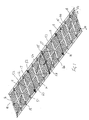
- the rigging deck module includes a deck body 10 comprising a webbing lattice 11 and an industrial PVC mesh deck surface members 12.
- the lattice 11 is formed by assembly from 50 mm wide, low-stretch, high modulus webbing 13 rated to 2500kg and comprising respective edge stringer 14 and medial webbing 15 interconnected by end webbing members 16 and transverse webbing members 17.
- Distributor webbing members 18 extend from the region of the corners and are secured to the medial webbing 15.
- the lattice 11 is secured to the deck surface members 12 by pocketing with 1000g/m 2 PVC pockets 20 secured by thermal welds 21 to the deck surface members 12.
- the deck surface member 12 is doubled over the upper surface of the edge stringer 14 and the joint is encapsulated by a 75 mm wide 1000g/m 2 PVC pocket 20 secured top and bottom by 50mm thermal welds 21.
- the deck surface member 12 is laid up to the medial webbing 15 and the webbing 15 is encapsulated by a 165 mm wide band of 1000g/m 2 PVC forming a 65mm pocket 20 secured at both sides by 50mm thermal welds 21.
- a further 165 mm wide reinforcing band 22 of 1000g/m 2 PVC is thermally welded to the opposite side of the deck surface member 12.
- respective deck surface members 12 are joined by overlapping at a transverse webbing member 17.
- the webbing 17 and overlap is encapsulated by a 165 mm wide band of 1000g/m 2 PVC forming a 65mm pocket 20 secured at both sides by 50mm thermal welds 21.
- a further 165 mm wide reinforcing band 23 of 1000g/m 2 PVC is thermally welded to the opposite side of the overlap.
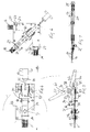
- Corner suspension means 24 are provided as illustrated in Figure 6 , and comprise a pair of corner plates 25 bolted together and entrapping the corner of the deck surface member 12 and the ends of the edge stringer 14 end webbing members 16.
- the lower plate of the corner plates 25 is typically 6mm 6061 alloy, T6 tempered and has three 55mm slots 26 formed therein. Each slot 26 is adapted to receive a bight of a respective one of the 50mm edge stringer 14, end webbing member 16 and distributor webbing member 18, the bight being retained against withdrawal by M10 retainer bolt 27 to positively terminate and transfer tensile loads from the webbing 14, 16 and 18 to the plate 25.
- the corner suspension means 24 supports a tensioning means comprising a ratchet strap winch assembly 30.
- the winch assembly 30 includes a swivel plate 31 pivoted to the corner suspension means 24 by M16 swivel bolt 32.
- a winch body 33 is pivotally mounted to a swivel lug 33 formed on the swivel plate 31 via horizontal pivot bolt 34 and retained by M10 retainer bolt 35.
- the winch handle 36 acts on a spindle 37 via drive pawl 40 and ratchet wheel 41 to tension load binder webbing 42 spooled onto the spindle 37.
- the spindle 37 is retained against unspooling of the tension load binder webbing 42 between handle strokes by pawl 43.
- a 2:1 mechanical advantage in tensioning force is provided by the end of the tension load binder webbing 42 being terminated by terminal loop 44 and carabineer 45 to the corner plates 25.
- supplementary suspension means 46 as illustrated in Figures 4 and 5 includes a 3mm 6061-T6 alloys upper plate 47 and a 6mm lower plate 50 of the same material, bolted together and entrapping the deck surface member 12 and the peripheral end webbing 16 or edge stringer 14.
- the lower plate 50 has a 55mm slot 26 formed therein adapted to receive a bight of the respective medial webbing member 15 or transverse webbing member 17, the bight being retained against withdrawal by M10 retainer bolt 27 to positively terminate and transfer tensile loads from the webbing 15, 17 to the plates 47, 50.
- the supplementary suspension means 46 may selectively mount a tensioning means comprising a ratchet strap winch assembly 30 as before. Otherwise, the supplementary suspension means 46 may be a static suspension point for securing to a substrate or to rigging strops by means such as a carabineer 51.
- the intersections of the medial webbing member and the transverse webbing members are provided with attachment holes 52 permitting selective stay attachment from above or below.
- Rigging strops 53 comprise steel wire cable 54 swaged to high tensile rings 55 forming securing points for the deck bodies.
- the rigging strops 53 are tensioned in mutually spaced relation to a structure (not shown). In the illustrated embodiment, rigging strops 53 are strung together to form a two-deck arrangement.
- the tension load binder webbing 42 passes through the rings to be terminated by terminal loop 44 and carabineer 45 to the corner plates 25 or supplementary suspension means 46 as the case requires.
- a compression strut 56 is disposed between the spaced rigging strops 53 at the ends of the deck bodies 10 and having the ends of the strut 56 affixed by carabineer 51 to the rings 55.
- the compression strut 56 is formed of 75mm OD by 7.0mm wall, tempered 6061 alloy tube fabricated to stainless steel end pieces. The end pieces include a horizontal pivot to allow the strut to find an equilibrium position in use. Similar spreaders 63 are disposed intermediate the ends of the deck body 10.
- the rigging deck of the above embodiment is a tensioned platform which is a primary support for work to replace aluminium scaffold, but used in a similar way to aluminium scaffold and also may be used where scaffolding has no access.
- the platform is versatile. Strength and minimal deflection are advantages. Whereas a safety net would deflect approx 1 m to 1200mm, a deck in accordance with the present invention will only deflect 200mm - 400mm with an applied weight of 250 kilo per square metre, approximating a semi rigid floor.
Landscapes
- Engineering & Computer Science (AREA)
- Architecture (AREA)
- Civil Engineering (AREA)
- Structural Engineering (AREA)
- Mechanical Engineering (AREA)
- General Engineering & Computer Science (AREA)
- Physics & Mathematics (AREA)
- Electromagnetism (AREA)
- Chemical & Material Sciences (AREA)
- Combustion & Propulsion (AREA)
- Ocean & Marine Engineering (AREA)
- Bridges Or Land Bridges (AREA)
- Emergency Lowering Means (AREA)
- Clamps And Clips (AREA)
- Refuge Islands, Traffic Blockers, Or Guard Fence (AREA)
- Lining Or Joining Of Plastics Or The Like (AREA)
- Moulding By Coating Moulds (AREA)
Claims (15)
- Montagedeckmodul, das Folgendes beinhaltet: einen Deckkörper (10) mit flexiblem Deckmaterial (12), das von einem gurtverstärkten Zugrand (14, 16) umgrenzt ist, Aufhängungsmitteln (24, 26), die um den Rand beabstandet sind, so dass der Deckkörper gespannt werden kann, um eine im Wesentlichen flache Deckfläche zu bilden, und einem Gitter (11) aus Zug-Gurtelementen, die an dem flexiblen Deckmaterial (12) und dem gurtverstärkten Zugrand (14, 16) befestigt sind;
Zug-Verspannungsstroppen (53), die ausgeführt sind, um an einer Struktur in aufrechterhaltener beabstandeter Beziehung zueinander unter Zugspannung montiert zu werden, und die jeweils daran ausgebildete Befestigungspunkte haben, dadurch gekennzeichnet, dass sich an jedem Aufhängungsmittel (24, 46) spannbare Verbindungsmittel zum Befestigen und Spannen des Deckkörpers (10) an jeweiligen Befestigungspunkten befinden. - Montagedeck nach Anspruch 1, wobei der Deckkörper (10) eine geheftete und geklebte und verschweißte Anordnung aus Polymerfolie oder Polymergewebe und ein Gurtbandgitter in darin gebildeten Taschen aufweist, wobei Schnittpunkte des Gurtbandgitters und des äußeren Rands des Deckkörpers die Aufhängungsmittel (24, 46) bilden.
- Montagedeck nach Anspruch 1, wobei die Zug-Verspannungsstroppen (53) aus einem oder mehr von Drahtseil, Kette, dehnungsarmem Gurtband und dehnungsarmem geflochtetem Seil ausgewählt sind.
- Montagedeck nach Anspruch 1, wobei die beabstandete Beziehung der Verspannungsstroppen (53) von Druckstreben (56), die zwischen den voneinander beabstandeten Verspannungsstroppen (53) an den Enden des Decks angeordnet sind, und dadurch, dass die Enden der Druckstrebe (56) mit Schäkeln oder anderweitig zwischen dem Befestigungspunktepaar, das ein Ende des Deckkörpers befestigt, fixiert sind, aufrechterhalten wird.
- Montagedeck nach Anspruch 4, wobei die Druckstrebe (56) rohrförmig ist und an Endstücken mit Montagemitteln einschließlich einem horizontalen Drehpunkt versehen sind, damit die Strebe im Gebrauch eine Gleichgewichtslage finden kann.
- Montagedeck nach Anspruch 1, wobei die spannbaren Verbindungsmittel, die sich zum Befestigen des Deckkörpers an einem jeweiligen Befestigungspunkt an jedem Aufhängungsmittel befinden, jeweils eine Windenanordnung (30) zum Bereitstellen der Spannung beinhalten.
- Montagedeck nach Anspruch 6, wobei die Windenanordnung (30) eine Montagebasis beinhaltet, die an dem Montagedeck befestigt ist und einen Lastbandzughub trägt, dessen Band ausgeführt sein kann, um an dem gespannten Verspannungsstropp (53) befestigt zu werden.
- Montagedeck nach Anspruch 7, wobei die Windenanordnung (30) mit einem Schwenkzapfen oder -bolzen an der Montagebasis befestigt ist, um die Ausrichtung der Windenspannung auf das Kraftzentrum am Deck zu ermöglichen.
- Montagedeck nach Anspruch 1, wobei eine oder mehr Lasttraversen (63) vorgesehen sind, die zwischen den beabstandeten Verspannungsstroppen (53) zwischen den Enden des Decks angeordnet sind, wobei die Lasttraverse (63) durch eine gemeinsame Anbringung mit einem ergänzenden Verbindungsglied, das den Deckkörper (10) mit dem Verspannungsstropp (53) verbindet, festgehalten wird.
- Montagedeck nach Anspruch 7, wobei die Lasttraverse (63) Endstücke beinhaltet, die einen horizontalen Drehpunkt haben, um es der Lasttraverse (63) zu ermöglichen, im Gebrauch eine Gleichgewichtslage zu finden.
- Montagedeck nach Anspruch 1, wobei der Deckkörper (10) rechteckig ist und jeweilige Deckkörper (10) ausgeführt sind, um in einer Ende-an-Ende-Beziehung eingesetzt zu werden.
- Montagedeck nach Anspruch 11, wobei das Gitter (11) aus Zug-Gurtelementen ein Paar voneinander beabstandete Außenrandteile beinhaltet, die durch mehrere voneinander beabstandete querverlaufende Gurtstücke (17) miteinander verbunden sind, wobei die querverlaufenden Gurtstücke (17) die Enden der Außenrandteile, die den verstärkten Zugrand (16) bilden, mit den Außenrandteilen verbinden.
- Montagedeck nach Anspruch 12, wobei der Deckkörper einen Mittelgurt (15) beinhaltet, der zu bzw. von den Außenrandteilen parallel und beabstandet ist und die querverlaufenden Gurtstücke (17) jeweils miteinander verbindet.
- Montagedeck nach Anspruch 13, wobei die vier Ecken, die von den querverlaufenden Gurtstücken (17) gebildet werden, die die Enden der Außenrandteile miteinander verbinden, jeweils ein Eckaufhängungsmittel (24) bereitstellen, das spannbare Verbindungsmittel hat, wobei die vier Eckaufhängungsmittel (24) jeweils einen Gurtbandlastverteiler (18) haben, der sich von dem Aufhängungspunkt zu einem Verteilerpunkt am Mittelgurt (15) weg von den am Rande liegenden querverlaufenden Gurtstücken (17) erstreckt.
- Montagedeck nach Anspruch 13, wobei die Enden des Mittelgurts zum Aufnehmen von Anschlussplatten zur Befestigung der Decks in Ende-an-Ende-Beziehung oder, wenn am Verlaufsende, Montieren eines spannbaren Verbindungsmittels (46), gestaltet sind.
Applications Claiming Priority (1)
| Application Number | Priority Date | Filing Date | Title |
|---|---|---|---|
| PCT/AU2008/000819 WO2009117758A1 (en) | 2008-06-10 | 2008-06-10 | Rigging deck module |
Publications (3)
| Publication Number | Publication Date |
|---|---|
| EP2310575A1 EP2310575A1 (de) | 2011-04-20 |
| EP2310575A4 EP2310575A4 (de) | 2014-06-18 |
| EP2310575B1 true EP2310575B1 (de) | 2016-02-10 |
Family
ID=41112843
Family Applications (1)
| Application Number | Title | Priority Date | Filing Date |
|---|---|---|---|
| EP08756902.6A Not-in-force EP2310575B1 (de) | 2008-06-10 | 2008-06-10 | Rigg-deckmodul |
Country Status (10)
| Country | Link |
|---|---|
| US (1) | US8627619B2 (de) |
| EP (1) | EP2310575B1 (de) |
| CN (1) | CN102057108B (de) |
| AU (1) | AU2008353317B2 (de) |
| CA (1) | CA2727151C (de) |
| DK (1) | DK2310575T3 (de) |
| EA (1) | EA022233B1 (de) |
| GB (1) | GB2460792B (de) |
| NZ (1) | NZ589790A (de) |
| WO (1) | WO2009117758A1 (de) |
Families Citing this family (9)
| Publication number | Priority date | Publication date | Assignee | Title |
|---|---|---|---|---|
| WO2011063457A1 (en) * | 2009-11-30 | 2011-06-03 | Decklite Ip Holdings Limited | Rigging deck module |
| WO2012173657A2 (en) | 2011-06-17 | 2012-12-20 | Wilkinson Merwin Hale Jr | Temporary platform for attachment to an offshore structure |
| US9038777B2 (en) * | 2012-10-15 | 2015-05-26 | James F. Stearns Company LLP | Fall protection system |
| GB2535705A (en) * | 2015-02-23 | 2016-08-31 | Spanset Inter Ag | Assembly of a platform assembly and support structure and method of assembly |
| US10165771B2 (en) * | 2015-04-10 | 2019-01-01 | Southern Flyway Outfitters, Llc | Apparatuses and methods for attracting and/or repelling animals |
| CA3079311A1 (en) | 2019-04-25 | 2020-10-25 | Dirk Otto Dorenbos | Rope protector and associated methods |
| CN113216120B (zh) * | 2021-05-07 | 2022-05-10 | 南通泰胜蓝岛海洋工程有限公司 | 一种用于海上升压站的钢格栅安装工艺 |
| US12433404B1 (en) * | 2023-02-27 | 2025-10-07 | Steve Long | Elevated storage net |
| GB202410022D0 (en) * | 2024-07-10 | 2024-08-21 | Proteamconsult Ltd | Cover for providing a floor structure over an opening |
Family Cites Families (39)
| Publication number | Priority date | Publication date | Assignee | Title |
|---|---|---|---|---|
| US2024904A (en) * | 1934-09-27 | 1935-12-17 | Ernest G Amesbury | Catwalk |
| US3527319A (en) * | 1969-08-15 | 1970-09-08 | Pedley Knowles & Co | Safety net |
| GB1530124A (en) * | 1974-11-18 | 1978-10-25 | Reed R | Staging for ship hulls and the like |
| GB1523655A (en) * | 1975-02-10 | 1978-09-06 | Armour Pharma | 4-(4-biphenylyl) butylamines and treatment of the animal organism therewith |
| US3949834A (en) * | 1975-03-19 | 1976-04-13 | Arthur Nusbaum | Safety net and adjustable support therefor |
| US4074791A (en) * | 1976-03-16 | 1978-02-21 | Inman Johnny K | Emergency fire net |
| US4389141A (en) * | 1980-12-31 | 1983-06-21 | Mobil Oil Corporation | Marine structure having a deck or work platform supported by absorbing mechanisms |
| US4721412A (en) | 1986-07-01 | 1988-01-26 | Robert D. King | Offshore safety escape platform |
| US4856615A (en) * | 1988-09-20 | 1989-08-15 | Arthur Nusbaum | Safety net arrangement for multi-floor buildings under construction, and method |
| US4892169A (en) * | 1989-02-21 | 1990-01-09 | Sinco, Inc. | Perimeter debris net lifting system |
| US4982813A (en) * | 1990-06-08 | 1991-01-08 | Sinco, Incorporated | Shock absorbing safety net |
| US4986389A (en) * | 1990-06-13 | 1991-01-22 | Westerbeke Fishing Gear Co., Inc. | Slidable safety net assembly |
| US5197239A (en) * | 1991-05-14 | 1993-03-30 | Sinco Incorporated | Containment system |
| US5161641A (en) * | 1991-10-29 | 1992-11-10 | Arthur Nusbaum | Jointly movable safety net and curtain arrangement for multi-floor buildings under construction |
| US5299654A (en) * | 1992-02-28 | 1994-04-05 | Sinco Incorporated | Safety net support system |
| AUPM287193A0 (en) * | 1993-12-09 | 1994-01-06 | Gale Australia Proprietary Limited | Canopy structures |
| US5582266A (en) * | 1994-09-15 | 1996-12-10 | Rexroad; John | Safety/debris net system |
| US5795267A (en) * | 1995-07-21 | 1998-08-18 | Playsmart, Inc. | Pre-tensioned floor system |
| US5579610A (en) * | 1995-08-03 | 1996-12-03 | Jackson; Robert L. | Leaf retaining net |
| US6035967A (en) * | 1995-11-01 | 2000-03-14 | Maeda; Hiroshi | Safety apparatus using parallel line catchers for elevated work site operations |
| US5787955A (en) * | 1996-01-25 | 1998-08-04 | Dargie; Roger A. | Secure tamper resistant safety net support system and assembly |
| US6098750A (en) * | 1997-11-24 | 2000-08-08 | Bay Nets, Inc. | Safety system |
| US6186274B1 (en) * | 1996-11-25 | 2001-02-13 | Bay Nets, Inc. | Safety system |
| US6161648A (en) * | 1997-10-01 | 2000-12-19 | Rexroad; John | Safety/debris net system |
| US6068085A (en) * | 1998-05-14 | 2000-05-30 | Sinco Inc. | Adjustable safety net methods and apparatus |
| US7169718B1 (en) * | 1998-11-18 | 2007-01-30 | John Rexroad | Shrink-net and system |
| AUPQ956800A0 (en) * | 2000-08-21 | 2000-09-14 | Safe.T.Nett Pty Ltd | Safety net |
| US6305310B1 (en) * | 2000-09-29 | 2001-10-23 | Stephanie L. Ferri | Boat safety net system |
| US20020104710A1 (en) * | 2000-12-27 | 2002-08-08 | Thompson Michael W. | Scaffold safety net |
| US6698604B2 (en) * | 2001-02-07 | 2004-03-02 | Sinco, Inc. | Net anchorage methods and apparatus |
| US6758306B2 (en) * | 2001-10-24 | 2004-07-06 | Jason D. Walls | Construction safety screen system |
| GB0326325D0 (en) * | 2003-11-12 | 2003-12-17 | Core Technical Services Ltd | Apparatus |
| CN2725163Y (zh) * | 2004-09-02 | 2005-09-14 | 中国人民解放军海军工程设计研究局 | 模块化浮箱间接头连接机构 |
| US20060090961A1 (en) * | 2004-11-02 | 2006-05-04 | John Rexroad | Safety net system |
| US20060201744A1 (en) * | 2005-03-14 | 2006-09-14 | Susan Curtis | Elevator shaft safety net system |
| US7389855B2 (en) * | 2005-03-24 | 2008-06-24 | John Rexroad | Free standing perimeter net system |
| US7448836B2 (en) * | 2005-04-22 | 2008-11-11 | D B Industries, Inc. | Load containment netting system |
| US20090159369A1 (en) * | 2006-02-13 | 2009-06-25 | Mccarthy Steve | Working platform |
| CN101016079A (zh) * | 2007-02-12 | 2007-08-15 | 孙正维 | 简便组装储放快速应用的海面临时漂浮路台 |
-
2008
- 2008-06-10 CA CA2727151A patent/CA2727151C/en not_active Expired - Fee Related
- 2008-06-10 US US12/997,550 patent/US8627619B2/en not_active Expired - Fee Related
- 2008-06-10 EP EP08756902.6A patent/EP2310575B1/de not_active Not-in-force
- 2008-06-10 NZ NZ589790A patent/NZ589790A/xx not_active IP Right Cessation
- 2008-06-10 DK DK08756902.6T patent/DK2310575T3/en active
- 2008-06-10 AU AU2008353317A patent/AU2008353317B2/en not_active Ceased
- 2008-06-10 EA EA201100011A patent/EA022233B1/ru not_active IP Right Cessation
- 2008-06-10 WO PCT/AU2008/000819 patent/WO2009117758A1/en not_active Ceased
- 2008-06-10 CN CN2008801297658A patent/CN102057108B/zh not_active Expired - Fee Related
-
2009
- 2009-10-12 GB GB0917725A patent/GB2460792B/en not_active Expired - Fee Related
Also Published As
| Publication number | Publication date |
|---|---|
| CN102057108B (zh) | 2012-05-09 |
| DK2310575T3 (en) | 2016-05-30 |
| US8627619B2 (en) | 2014-01-14 |
| GB2460792B (en) | 2010-05-26 |
| EA022233B1 (ru) | 2015-11-30 |
| GB2460792A (en) | 2009-12-16 |
| EP2310575A4 (de) | 2014-06-18 |
| CN102057108A (zh) | 2011-05-11 |
| NZ589790A (en) | 2013-08-30 |
| GB0917725D0 (en) | 2009-11-25 |
| EP2310575A1 (de) | 2011-04-20 |
| US20110302868A1 (en) | 2011-12-15 |
| CA2727151A1 (en) | 2009-10-01 |
| AU2008353317A1 (en) | 2009-10-01 |
| CA2727151C (en) | 2015-10-06 |
| WO2009117758A1 (en) | 2009-10-01 |
| EA201100011A1 (ru) | 2011-10-31 |
| AU2008353317B2 (en) | 2015-10-29 |
Similar Documents
| Publication | Publication Date | Title |
|---|---|---|
| EP2310575B1 (de) | Rigg-deckmodul | |
| US9038777B2 (en) | Fall protection system | |
| US10329781B2 (en) | Safety barrier netting system | |
| US9528285B2 (en) | Safety barrier netting system with rigid panel net supports and stopper mechanisms | |
| US11401668B1 (en) | Method of suspending a platform from a bridge main cable | |
| US9957138B2 (en) | Device and method for lifting circular structures | |
| CA2419230A1 (en) | Suspended jig for roof construction | |
| CN105586832A (zh) | 悬挂式猫道面网安装系统 | |
| AU2006269837B2 (en) | Working platform | |
| AU2020100560B4 (en) | A shroud | |
| US7252315B2 (en) | System and method for personnel transfer | |
| CN106049848B (zh) | 一种可调式防晃移动平台及其安装方法 | |
| CN115776968A (zh) | 用于自升式起重机的延伸轭、具有延伸轭的自升式风力涡轮机起重机以及延伸轭的用途 | |
| WO2011063457A1 (en) | Rigging deck module | |
| GB2377914A (en) | Support means for a safety apparatus for delivery vehicles | |
| US9352804B2 (en) | Nautical railing | |
| CN223852067U (zh) | 海上光伏的光伏支架吊装结构 | |
| RU10185U1 (ru) | Наплавной мост из пенопласта и устройство для его изготовления |
Legal Events
| Date | Code | Title | Description |
|---|---|---|---|
| PUAI | Public reference made under article 153(3) epc to a published international application that has entered the european phase |
Free format text: ORIGINAL CODE: 0009012 |
|
| 17P | Request for examination filed |
Effective date: 20101209 |
|
| AK | Designated contracting states |
Kind code of ref document: A1 Designated state(s): AT BE BG CH CY CZ DE DK EE ES FI FR GB GR HR HU IE IS IT LI LT LU LV MC MT NL NO PL PT RO SE SI SK TR |
|
| AX | Request for extension of the european patent |
Extension state: AL BA MK RS |
|
| DAX | Request for extension of the european patent (deleted) | ||
| A4 | Supplementary search report drawn up and despatched |
Effective date: 20140515 |
|
| RIC1 | Information provided on ipc code assigned before grant |
Ipc: E04B 5/43 20060101ALI20140509BHEP Ipc: B63B 35/44 20060101ALI20140509BHEP Ipc: E04G 3/20 20060101ALI20140509BHEP Ipc: E04G 21/32 20060101ALI20140509BHEP Ipc: E02B 17/00 20060101AFI20140509BHEP |
|
| GRAP | Despatch of communication of intention to grant a patent |
Free format text: ORIGINAL CODE: EPIDOSNIGR1 |
|
| INTG | Intention to grant announced |
Effective date: 20150803 |
|
| RBV | Designated contracting states (corrected) |
Designated state(s): AT BE BG CH CY CZ DE DK EE ES FI FR GR HR HU IE IS IT LI LT LU LV MC MT NL NO PL PT RO SE SI SK TR |
|
| GRAS | Grant fee paid |
Free format text: ORIGINAL CODE: EPIDOSNIGR3 |
|
| GRAA | (expected) grant |
Free format text: ORIGINAL CODE: 0009210 |
|
| AK | Designated contracting states |
Kind code of ref document: B1 Designated state(s): AT BE BG CH CY CZ DE DK EE ES FI FR GR HR HU IE IS IT LI LT LU LV MC MT NL NO PL PT RO SE SI SK TR |
|
| REG | Reference to a national code |
Ref country code: AT Ref legal event code: REF Ref document number: 774719 Country of ref document: AT Kind code of ref document: T Effective date: 20160215 Ref country code: CH Ref legal event code: EP |
|
| REG | Reference to a national code |
Ref country code: IE Ref legal event code: FG4D |
|
| REG | Reference to a national code |
Ref country code: DE Ref legal event code: R096 Ref document number: 602008042287 Country of ref document: DE |
|
| REG | Reference to a national code |
Ref country code: NL Ref legal event code: FP |
|
| REG | Reference to a national code |
Ref country code: DK Ref legal event code: T3 Effective date: 20160523 |
|
| REG | Reference to a national code |
Ref country code: LT Ref legal event code: MG4D |
|
| REG | Reference to a national code |
Ref country code: NO Ref legal event code: T2 Effective date: 20160210 |
|
| REG | Reference to a national code |
Ref country code: AT Ref legal event code: MK05 Ref document number: 774719 Country of ref document: AT Kind code of ref document: T Effective date: 20160210 |
|
| PG25 | Lapsed in a contracting state [announced via postgrant information from national office to epo] |
Ref country code: HR Free format text: LAPSE BECAUSE OF FAILURE TO SUBMIT A TRANSLATION OF THE DESCRIPTION OR TO PAY THE FEE WITHIN THE PRESCRIBED TIME-LIMIT Effective date: 20160210 Ref country code: ES Free format text: LAPSE BECAUSE OF FAILURE TO SUBMIT A TRANSLATION OF THE DESCRIPTION OR TO PAY THE FEE WITHIN THE PRESCRIBED TIME-LIMIT Effective date: 20160210 Ref country code: IT Free format text: LAPSE BECAUSE OF FAILURE TO SUBMIT A TRANSLATION OF THE DESCRIPTION OR TO PAY THE FEE WITHIN THE PRESCRIBED TIME-LIMIT Effective date: 20160210 Ref country code: FI Free format text: LAPSE BECAUSE OF FAILURE TO SUBMIT A TRANSLATION OF THE DESCRIPTION OR TO PAY THE FEE WITHIN THE PRESCRIBED TIME-LIMIT Effective date: 20160210 Ref country code: GR Free format text: LAPSE BECAUSE OF FAILURE TO SUBMIT A TRANSLATION OF THE DESCRIPTION OR TO PAY THE FEE WITHIN THE PRESCRIBED TIME-LIMIT Effective date: 20160511 |
|
| PG25 | Lapsed in a contracting state [announced via postgrant information from national office to epo] |
Ref country code: SE Free format text: LAPSE BECAUSE OF FAILURE TO SUBMIT A TRANSLATION OF THE DESCRIPTION OR TO PAY THE FEE WITHIN THE PRESCRIBED TIME-LIMIT Effective date: 20160210 Ref country code: IS Free format text: LAPSE BECAUSE OF FAILURE TO SUBMIT A TRANSLATION OF THE DESCRIPTION OR TO PAY THE FEE WITHIN THE PRESCRIBED TIME-LIMIT Effective date: 20160610 Ref country code: LT Free format text: LAPSE BECAUSE OF FAILURE TO SUBMIT A TRANSLATION OF THE DESCRIPTION OR TO PAY THE FEE WITHIN THE PRESCRIBED TIME-LIMIT Effective date: 20160210 Ref country code: PT Free format text: LAPSE BECAUSE OF FAILURE TO SUBMIT A TRANSLATION OF THE DESCRIPTION OR TO PAY THE FEE WITHIN THE PRESCRIBED TIME-LIMIT Effective date: 20160613 Ref country code: AT Free format text: LAPSE BECAUSE OF FAILURE TO SUBMIT A TRANSLATION OF THE DESCRIPTION OR TO PAY THE FEE WITHIN THE PRESCRIBED TIME-LIMIT Effective date: 20160210 Ref country code: PL Free format text: LAPSE BECAUSE OF FAILURE TO SUBMIT A TRANSLATION OF THE DESCRIPTION OR TO PAY THE FEE WITHIN THE PRESCRIBED TIME-LIMIT Effective date: 20160210 Ref country code: LV Free format text: LAPSE BECAUSE OF FAILURE TO SUBMIT A TRANSLATION OF THE DESCRIPTION OR TO PAY THE FEE WITHIN THE PRESCRIBED TIME-LIMIT Effective date: 20160210 |
|
| PG25 | Lapsed in a contracting state [announced via postgrant information from national office to epo] |
Ref country code: EE Free format text: LAPSE BECAUSE OF FAILURE TO SUBMIT A TRANSLATION OF THE DESCRIPTION OR TO PAY THE FEE WITHIN THE PRESCRIBED TIME-LIMIT Effective date: 20160210 |
|
| REG | Reference to a national code |
Ref country code: DE Ref legal event code: R097 Ref document number: 602008042287 Country of ref document: DE |
|
| PG25 | Lapsed in a contracting state [announced via postgrant information from national office to epo] |
Ref country code: SK Free format text: LAPSE BECAUSE OF FAILURE TO SUBMIT A TRANSLATION OF THE DESCRIPTION OR TO PAY THE FEE WITHIN THE PRESCRIBED TIME-LIMIT Effective date: 20160210 Ref country code: RO Free format text: LAPSE BECAUSE OF FAILURE TO SUBMIT A TRANSLATION OF THE DESCRIPTION OR TO PAY THE FEE WITHIN THE PRESCRIBED TIME-LIMIT Effective date: 20160210 Ref country code: CZ Free format text: LAPSE BECAUSE OF FAILURE TO SUBMIT A TRANSLATION OF THE DESCRIPTION OR TO PAY THE FEE WITHIN THE PRESCRIBED TIME-LIMIT Effective date: 20160210 |
|
| PLBE | No opposition filed within time limit |
Free format text: ORIGINAL CODE: 0009261 |
|
| STAA | Information on the status of an ep patent application or granted ep patent |
Free format text: STATUS: NO OPPOSITION FILED WITHIN TIME LIMIT |
|
| PG25 | Lapsed in a contracting state [announced via postgrant information from national office to epo] |
Ref country code: BE Free format text: LAPSE BECAUSE OF FAILURE TO SUBMIT A TRANSLATION OF THE DESCRIPTION OR TO PAY THE FEE WITHIN THE PRESCRIBED TIME-LIMIT Effective date: 20160210 |
|
| 26N | No opposition filed |
Effective date: 20161111 |
|
| PG25 | Lapsed in a contracting state [announced via postgrant information from national office to epo] |
Ref country code: MC Free format text: LAPSE BECAUSE OF FAILURE TO SUBMIT A TRANSLATION OF THE DESCRIPTION OR TO PAY THE FEE WITHIN THE PRESCRIBED TIME-LIMIT Effective date: 20160210 |
|
| REG | Reference to a national code |
Ref country code: CH Ref legal event code: PL |
|
| PG25 | Lapsed in a contracting state [announced via postgrant information from national office to epo] |
Ref country code: SI Free format text: LAPSE BECAUSE OF FAILURE TO SUBMIT A TRANSLATION OF THE DESCRIPTION OR TO PAY THE FEE WITHIN THE PRESCRIBED TIME-LIMIT Effective date: 20160210 Ref country code: BG Free format text: LAPSE BECAUSE OF FAILURE TO SUBMIT A TRANSLATION OF THE DESCRIPTION OR TO PAY THE FEE WITHIN THE PRESCRIBED TIME-LIMIT Effective date: 20160510 |
|
| REG | Reference to a national code |
Ref country code: IE Ref legal event code: MM4A |
|
| REG | Reference to a national code |
Ref country code: FR Ref legal event code: ST Effective date: 20170228 |
|
| PG25 | Lapsed in a contracting state [announced via postgrant information from national office to epo] |
Ref country code: CH Free format text: LAPSE BECAUSE OF NON-PAYMENT OF DUE FEES Effective date: 20160630 Ref country code: FR Free format text: LAPSE BECAUSE OF NON-PAYMENT OF DUE FEES Effective date: 20160630 Ref country code: LI Free format text: LAPSE BECAUSE OF NON-PAYMENT OF DUE FEES Effective date: 20160630 |
|
| PG25 | Lapsed in a contracting state [announced via postgrant information from national office to epo] |
Ref country code: IE Free format text: LAPSE BECAUSE OF NON-PAYMENT OF DUE FEES Effective date: 20160610 |
|
| PG25 | Lapsed in a contracting state [announced via postgrant information from national office to epo] |
Ref country code: HU Free format text: LAPSE BECAUSE OF FAILURE TO SUBMIT A TRANSLATION OF THE DESCRIPTION OR TO PAY THE FEE WITHIN THE PRESCRIBED TIME-LIMIT; INVALID AB INITIO Effective date: 20080610 Ref country code: CY Free format text: LAPSE BECAUSE OF FAILURE TO SUBMIT A TRANSLATION OF THE DESCRIPTION OR TO PAY THE FEE WITHIN THE PRESCRIBED TIME-LIMIT Effective date: 20160210 |
|
| PG25 | Lapsed in a contracting state [announced via postgrant information from national office to epo] |
Ref country code: TR Free format text: LAPSE BECAUSE OF FAILURE TO SUBMIT A TRANSLATION OF THE DESCRIPTION OR TO PAY THE FEE WITHIN THE PRESCRIBED TIME-LIMIT Effective date: 20160210 Ref country code: MT Free format text: LAPSE BECAUSE OF NON-PAYMENT OF DUE FEES Effective date: 20160630 Ref country code: LU Free format text: LAPSE BECAUSE OF NON-PAYMENT OF DUE FEES Effective date: 20160610 |
|
| PGFP | Annual fee paid to national office [announced via postgrant information from national office to epo] |
Ref country code: NO Payment date: 20180627 Year of fee payment: 11 |
|
| PGFP | Annual fee paid to national office [announced via postgrant information from national office to epo] |
Ref country code: DE Payment date: 20180628 Year of fee payment: 11 |
|
| PGFP | Annual fee paid to national office [announced via postgrant information from national office to epo] |
Ref country code: DK Payment date: 20180627 Year of fee payment: 11 Ref country code: NL Payment date: 20180924 Year of fee payment: 11 |
|
| REG | Reference to a national code |
Ref country code: DE Ref legal event code: R119 Ref document number: 602008042287 Country of ref document: DE |
|
| REG | Reference to a national code |
Ref country code: DK Ref legal event code: EBP Effective date: 20190630 |
|
| REG | Reference to a national code |
Ref country code: NO Ref legal event code: MMEP |
|
| REG | Reference to a national code |
Ref country code: NL Ref legal event code: MM Effective date: 20190701 |
|
| PG25 | Lapsed in a contracting state [announced via postgrant information from national office to epo] |
Ref country code: NL Free format text: LAPSE BECAUSE OF NON-PAYMENT OF DUE FEES Effective date: 20190701 Ref country code: DE Free format text: LAPSE BECAUSE OF NON-PAYMENT OF DUE FEES Effective date: 20200101 Ref country code: NO Free format text: LAPSE BECAUSE OF NON-PAYMENT OF DUE FEES Effective date: 20190630 |
|
| PG25 | Lapsed in a contracting state [announced via postgrant information from national office to epo] |
Ref country code: DK Free format text: LAPSE BECAUSE OF NON-PAYMENT OF DUE FEES Effective date: 20190630 |