EP2310607B1 - Vorhangvorrichtung für eine gebäudeöffnung - Google Patents
Vorhangvorrichtung für eine gebäudeöffnung Download PDFInfo
- Publication number
- EP2310607B1 EP2310607B1 EP09772508.9A EP09772508A EP2310607B1 EP 2310607 B1 EP2310607 B1 EP 2310607B1 EP 09772508 A EP09772508 A EP 09772508A EP 2310607 B1 EP2310607 B1 EP 2310607B1
- Authority
- EP
- European Patent Office
- Prior art keywords
- wall
- closure
- rigid
- pair
- flexible
- Prior art date
- Legal status (The legal status is an assumption and is not a legal conclusion. Google has not performed a legal analysis and makes no representation as to the accuracy of the status listed.)
- Active
Links
Images




Classifications
-
- E—FIXED CONSTRUCTIONS
- E06—DOORS, WINDOWS, SHUTTERS, OR ROLLER BLINDS IN GENERAL; LADDERS
- E06B—FIXED OR MOVABLE CLOSURES FOR OPENINGS IN BUILDINGS, VEHICLES, FENCES OR LIKE ENCLOSURES IN GENERAL, e.g. DOORS, WINDOWS, BLINDS, GATES
- E06B3/00—Window sashes, door leaves, or like elements for closing wall or like openings; Layout of fixed or moving closures, e.g. windows in wall or like openings; Features of rigidly-mounted outer frames relating to the mounting of wing frames
- E06B3/32—Arrangements of wings characterised by the manner of movement; Arrangements of movable wings in openings; Features of wings or frames relating solely to the manner of movement of the wing
- E06B3/48—Wings connected at their edges, e.g. foldable wings
- E06B3/481—Wings foldable in a zig-zag manner or bi-fold wings
- E06B3/483—Wings foldable in a zig-zag manner or bi-fold wings folding upwardly
-
- E—FIXED CONSTRUCTIONS
- E06—DOORS, WINDOWS, SHUTTERS, OR ROLLER BLINDS IN GENERAL; LADDERS
- E06B—FIXED OR MOVABLE CLOSURES FOR OPENINGS IN BUILDINGS, VEHICLES, FENCES OR LIKE ENCLOSURES IN GENERAL, e.g. DOORS, WINDOWS, BLINDS, GATES
- E06B9/00—Screening or protective devices for wall or similar openings, with or without operating or securing mechanisms; Closures of similar construction
- E06B9/02—Shutters, movable grilles, or other safety closing devices, e.g. against burglary
- E06B9/06—Shutters, movable grilles, or other safety closing devices, e.g. against burglary collapsible or foldable, e.g. of the bellows or lazy-tongs type
- E06B9/0607—Shutters, movable grilles, or other safety closing devices, e.g. against burglary collapsible or foldable, e.g. of the bellows or lazy-tongs type comprising a plurality of similar rigid closing elements movable to a storage position
-
- E—FIXED CONSTRUCTIONS
- E06—DOORS, WINDOWS, SHUTTERS, OR ROLLER BLINDS IN GENERAL; LADDERS
- E06B—FIXED OR MOVABLE CLOSURES FOR OPENINGS IN BUILDINGS, VEHICLES, FENCES OR LIKE ENCLOSURES IN GENERAL, e.g. DOORS, WINDOWS, BLINDS, GATES
- E06B9/00—Screening or protective devices for wall or similar openings, with or without operating or securing mechanisms; Closures of similar construction
- E06B9/02—Shutters, movable grilles, or other safety closing devices, e.g. against burglary
- E06B9/06—Shutters, movable grilles, or other safety closing devices, e.g. against burglary collapsible or foldable, e.g. of the bellows or lazy-tongs type
- E06B9/0692—Shutters, movable grilles, or other safety closing devices, e.g. against burglary collapsible or foldable, e.g. of the bellows or lazy-tongs type comprising flexible sheets as closing screen
Definitions
- the present invention is in the field of materials used to ensure the closure of building bays and relates more particularly to a movable flexible curtain closing device.
- Known flexible curtain closing devices are known from the state of the art from the bottom upwards and vice versa, the advantage of which, because of their lightness, is to allow rapid opening and closing movements (speed of movement included). between one meter per second and 3 meters per second).
- a closure device comprising a flexible curtain stiffened by a succession of regularly spaced horizontal stiffeners, engaged by its two lateral edges in two vertical boxes of a frame structure bordering the lateral edges of the bay and the edge superior of the latter.
- the curtain By its upper part, the curtain is engaged in a horizontal upper box carried by the two side boxes.
- the stiffeners are laterally juxtaposed at the top in the upper horizontal box of the frame structure and the curtain forms a succession of folds under these stiffeners in the width of the vertical boxes.
- the disadvantage of such a solution is that it requires a box width and therefore a footprint all the more important that the curtain comprises stiffeners which in practice limits their number or size.
- This folding door structure comprises a door leaf divided into a series of horizontal panels constituted by rigid panels alternated with flexible fabric panels, each of the rigid panels being mounted at its ends in a pair of guide rails of its own.
- the pairs of guide rails are juxtaposed according to the depth of the opening and their number depends on the number of flexible panel.
- the thickness of the door structure and therefore the footprint of the latter depends on the number of rigid panel.
- This door structure comprises an opening and closing means of maneuver consisting of a winching device formed of a toothed belt or an endless chain stretched between an upper pulley and a lower pulley, the upper pulley being coupled to a shaft drive engaged with the output shaft of a drive member.
- the lower rigid panel is attached to the endless belt.
- Patent is known US 3,313,338 a door structure whose apron is formed of a succession of rigid panels each mounted sliding in a pair of dedicated guide rail.
- the pairs of guide rails are arranged in a juxtaposed manner and their number, equal to the number of panels significantly increases the footprint.
- the lower panel cooperates with an opening and closing actuation mechanism comprising traction cables and each panel has a driving nosepiece which acts in thrust on a nose of the next upper panel in order to drive the latter upwards to the top. during the opening movement. In fully open position the panels are in a juxtaposed state above the opening.
- the object of the present invention is to solve the aforementioned problems by proposing a closure device implementing another folding mode of the flexible curtain leading to reducing the footprint of the framing structure, this footprint remaining independent of the number stiffeners and panels used.
- Another object of the present invention is the implementation of a curtain closure device that can be used even with low lintel fallout and following crawling roofs.
- Another object of the present invention is to provide a curtain closure device for easy assembly and operation.
- the closure device for building bay comprising a guide structure formed of vertical guide rails at least partially or substantially vertically at least in part, fixed against the bay of the building and an apron in the form of flexible curtain movable in the guide structure between an open position and a closed position of the bay and vice versa and this by the action of a motorized traction cable drive means, the lower part of the apron being formed by a rigid closing wall to which the traction cables are attached, the upper part of the apron being formed of at least one flexible closing wall and being fixed by its lower horizontal border to the closure wall and by its horizontal upper edge to the lintel of the bay, is characterized in that each guide rail has a substantially vertical vertical rail segment and an upper rail segment, occupying a horizontal or substantially horizontal spatial position by being inclined upwards or a position inclined with respect to the vertical, this segment being provided to receive the deck in the open position of the bay, in this position the deck being folded on itself.
- the rigid closing wall of the deck comes to bear on the threshold of the bay and the flexible shutter wall of the deck occupies a state of extension possibly slightly tension between the rigid shutter wall and the lintel from the bay.
- the rigid shutter wall is driven upwards by the drive means and the flexible sealing wall, during this movement, under the influence of its weight comes to fall back on itself laterally to the rigid shutter wall.
- the movement of the rigid closing wall along the guide structure continues, the lower horizontal edge of the lower part of the deck is made to occupy a level greater or identical to the level occupied by its border higher. This upper part of the deck then occupies an upper position above the bay.
- the establishment of the closure device according to the invention can be carried out even with a low lintel fallout.
- the upper part of the deck is formed by a flexible wall in one piece, but, according to an alternative embodiment, the upper part of the deck is formed by at least two closure walls flexible and at least one rigid closing wall interposed between the two flexible closure walls.
- the rigid closing wall comprises an upper pair of guide rollers and a lower pair of guide rollers both engaged in the same pair of guide rails.
- the upper part of the deck is formed by at least two flexible closing walls and at least one rigid closure wall interposed between the two flexible closure walls.
- the or each rigid closure wall comprises a pair of upper guide rollers cooperating in guiding with the same first pair of guide rails and a pair of lower guide rollers cooperating with a second pair of rails. guide adjacent to the preceding and disposed between the bay and the first pair of guide rails.
- the apron comprises a rigid shutter wall forming its lower part, and at least one other rigid closing wall distant from the previous one in the closed position of the bay, each rigid wall having at least least one abutment means and the abutment means of each closure wall cooperating in abutment with the abutment means of the immediately higher wall and / or of the closing wall immediately below so that each immediately lower wall leads during its upward movement towards the open position, the immediately higher wall.
- the stop means that each rigid wall has, is carried by the upper edge of said wall and forms a lateral projection relative to the latter, the upper pair of rollers is offset laterally with respect to the upper edge of said rigid wall and on the same side as the projection formed by the abutment means and the normal distance between the upper edge of said rigid wall and the axis of rotation of the rollers of the upper pair of rollers has been increasing since the rigid lower shutter wall to the rigid upper wall shutter.
- Such an arrangement is intended to facilitate the juxtaposition of rigid shutter walls during the opening movement.
- the or each flexible closure wall comprises at least one horizontal stiffener to give said wall a certain rigidity in the direction of the width of the opening that determines the bay.
- the stiffener projects laterally from the corresponding flexible wall and engages at its ends in a pair of dedicated rails.
- each flexible closure wall at least one elastic cable, attached to the upper and lower horizontal edges of said wall, said cable being supported on one of the faces of said wall and on the associated stiffener, and at least in the extended position of said flexible wall, said cable being in extension between the upper and lower edges of said wall.
- This arrangement is favorable, during opening, to favor the formation of the folds of the flexible wall on one side or the other and not randomly on both sides of the vertical plane that this wall determines in the closed position.
- the elastic cable is also fixed to the stiffener.
- the stiffener during the opening movement of the bay, under the effect of the tensile force applied to it by the elastic cable, is pulled upward in its lateral guide rails.
- This characteristic combined with a divergent arrangement of the guide rails of the stiffener and the rigid frame makes it possible to spread laterally the stiffener of the trajectory of the rigid frame and during opening or closing, thus avoiding the friction of the part. apron developing under the stiffener.
- the or each rigid closing wall is formed by a rigid frame comprising at least one horizontal spar occupying an upper position and two vertical lateral cross members attached to the spar and extending downwards. from the latter, this rigid frame receiving a filling wall.
- the rigid frame comprises a rigid lower spar fixed at its ends to its two vertical crosspieces; but according to another embodiment, the rigid frame does not include a lower spar, but instead, a horizontal elastic link, mounted in tension between the two vertical cross members of the frame.
- the frame in order to ensure its rigidity, will include an intermediate horizontal beam, fixed to the two horizontal crosspieces, at a distance from their lower end.
- a rigid frame arrangement with elastic link in the lower part has the advantage of eliminating or greatly reduce the risk of serious injury to a person in the path of the deck during its closing movement.
- Another advantage is to reduce the risk of damage to the rigid frame under the effect of a shock on the latter due for example to a mobile moving through the opening of the bay.
- the rigid frame may be formed of two parts articulated to each other along a horizontal axis. This arrangement is conducive to facilitate the evolution of the lower part of the deck along a curved portion of rail.
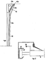
- the closure device 1 for the building bay 2 comprises a guiding structure 3 fixed to the jambs of the bay and laterally to the opening 20 that determines the latter and an apron 4 under flexible curtain shape, movable in the guide structure 3 between an open position and a closed position of the rack, this guide structure comprising a pair of guide rails 30.
- Each guide rail 30 has a vertical lower rail segment 30a or substantially vertical running at least over the entire height of the bay 2 and an upper rail segment 30b, occupying a horizontal or substantially horizontal spatial position by being inclined upwards to to follow the slope of the roof structure, or a position inclined relative to the vertical, this segment being provided to receive the deck 4 in the open position of the bay 2.
- the segment 30b of each rail 30 is located in part or entirely above the opening of the bay.
- the apron 4 is movable between the two aforementioned positions under the effect of the action of a drive means 5 motorized.
- the drive means 5 may consist of a horizontal winding bar 50 mounted above the opening of the bay, in two end bearings 51, and possibly in one or more intermediate stages. At this winding bar is coupled an electric motor 52. On this bar are fixed at a distance from each other at least two winding drums of two drive cables 54 of the apron 4.
- each drive cable 54 may be housed in the guide structure and will be fixed at its lower end to the deck 4 via a suitable element such as tab and the like.
- This element can also be the body of a collision protection mechanism integral with the deck 4.
- the drive cable may be constituted by a strap.
- the electric motor 52 may be wired, wireless or infrared.
- the lower part 40 of the apron 4 is formed by a rigid closure wall in one or more parts hinged to each other.
- This lower wall preferably consists of a rigid frame 40a defining a rectangular contour, to which the traction cables 54 are fixed, this rigid frame receiving a filling wall 41.
- the two cables of FIG. traction are attached to the lower part of the rigid wall 40 by the means previously described.
- the rigid frame 40a constituting the rigid wall 40, is formed of at least one upper horizontal spar and two vertical side rails attached to the upper spar and extending downwardly therefrom.
- the or each beam and each cross member may be made of steel or plastic.
- the filling wall 41 is preferentially flexible and consists preferentially of an impermeable sheet with air and water. This filling wall is sealingly attached to the longitudinal members and cross members of the rigid frame 40a.
- the upper part 45 of the apron is formed of at least one flexible wall in the form of a canvas or tarpaulin, preferably impervious to water and air, and is sealingly attached by its lower horizontal border to the rigid wall of shutter 40 and still in a sealed manner, by its upper horizontal border, to the lintel 21 of the bay 2.
- the height of the flexible wall 45 is equal to or greater than the height of the rigid wall 40.
- the rigid closure wall 40 In the closed position of the opening 20 of the bay 2, the rigid closure wall 40, by its lower edge, bears against the threshold of the opening and by its two beams, sleepers and filling wall 41 comes resting against the jambs of the bay outside the opening 20.
- the upper part 45 of the deck 4 In this position the upper part 45 of the deck 4 is vertically deployed and is stretched between the lintel and the frame 40a of the wall 40 and under the effect of this tension bears against the jambs of the bay and this outside the opening 20.
- the apron 4 In the fully open position of the bay, the apron 4 is folded on itself and is located above the opening 20 of the bay 2.
- the rigid closure wall 40 comprises lateral guiding means in the form of rollers 42, 43 with horizontal axes of rotation cooperating in guiding with the guide structure 3.
- rollers 42 and 43 are arranged in two pairs of rollers. namely an upper pair of rollers 42 and a lower pair of rollers 43.
- FIGS 1 to 4 there is shown a closure device according to a first embodiment. These figures show a device whose upper part of the apron 4 is integrally formed of a flexible wall 45 in one piece. It can be observed in these figures that the height of the rigid frame is slightly less than the height of the flexible wall 45.
- FIG 3 there is shown a device according to the first embodiment, during opening movement.
- the lower part of the apron that is to say the rigid shutter wall 40
- the flexible wall 45 folds on itself under the effect of its weight, laterally to the rigid closure wall 40, between the latter and the opening 20 of the bay 2.
- FIG 4 is shown a device according to the first embodiment, in the total position of opening of the bay. In this position, the apron is folded on itself in the rail portions 30b 30. It can be seen that the rigid closure wall 40 is arranged for the most part in the upper segment 30b of each guide rail 30 and that the flexible wall 45 is maintained in tension between the lintel of the bay 20 and the corresponding spar of said rigid wall 40.
- FIG. 5 to 8 there is shown a device according to a second embodiment.
- the upper part 45 of the deck 4 is formed by at least two flexible rectangular closure walls 45a and at least one rectangular rigid closure wall 45b interposed between the two flexible walls 45a.
- the rigid closure wall 45b consists of a rigid frame receiving a filling wall 45c. This rigid frame being identical to the frame 40a it will not be described in detail.
- the rigid closure wall 45b has an upper pair of guide rollers 42 and a lower pair of guide rollers 43.
- the upper pairs of guide rollers 42 of the rigid closure walls 40 and 45b are engaged in one and the same first pair of guide rails 30 and the lower pairs of guide rollers 43 of the rigid walls of FIG. shutter 40 and 45b are engaged in one and the same second pair of guide rails 31 adjacent to the preceding one and disposed between the bay 2 and the first pair of rails 30.
- each rigid closure wall 40, 45b comprises at least one stop means 44 and the abutment means of each wall 40, 45b cooperates in abutment with the abutment means of the immediately higher rigid wall and / or the rigid wall immediately below so that each wall, immediately below, causes during its upward movement to the open position, the rigid wall immediately higher.
- the stop means 44 that each rigid wall 40, 45b has, is carried by the upper spar of the rigid frame of this wall and forms lateral projection relative to the latter.
- the upper pair of rollers is offset laterally relative to the upper spar of the rigid frame of the corresponding wall and on the same side as the projection formed by the stop means 44.
- the normal distance between the upper beam of the frame and the axis of rotation of the rollers of the upper pair of rollers is increasing from the lower rigid wall 40 to the upper rigid wall 45b.
- the or each flexible wall comprises at least one horizontal stiffener 46 fixed to said wall in any known manner, at a distance from its upper and lower edges.
- the stiffener occupies a median position between these two edges.
- This stiffener 46 known per se, consists of a straight section of appropriate cross section.
- each stiffener 46 protrudes laterally from the corresponding flexible sealing wall and engages in a pair of dedicated rails 32, common to all the stiffeners, adjacent to the previous pair (s) of rails 30, 31.
- the stiffener 46 comprises at each end a guide roller 47 provided to be engaged in the corresponding rail 32.
- the rail 32 does not need to occupy the full height of the bay, since the stiffener 46, in the fully closed position, is located at a distance from the ground.
- each rail 32 has a substantially vertical lower segment of rail 32a extended by an upper segment of horizontal or substantially horizontal rail 32b adjacent to the rail segment 30b of rail 30.
- the flexible wall 45 or 45a is associated with at least one elastic cable 60, attached to the upper and lower horizontal edges of this wall.
- This elastic cable 60 grows vertically while being supported on one of the faces of said wall and on the associated stiffener 46.
- the Elastic cable 60 is an extension between the upper and lower borders of said flexible wall 45.
- the same stiffener 46 and elastic cable 60 may be applied to the flexible wall 45a of the embodiment corresponding to the Figures 5 to 8 .
- the elastic cable 60 is fixed to the stiffener 46 by any means known to those skilled in the art.
- the stiffener 46 during the opening movement of the bay, under the effect of the tensile force applied to it by the elastic cable 60, is pulled upwards in its lateral guide rails 32.
- This characteristic combined with a divergent spatial arrangement of the guide rail segments 30a, 32a, in their upper part makes it possible to spread laterally the stiffener 46 of the trajectory of the rigid wall 40 and thus to avoid any friction of the part of the deck developing under the stiffener 46.
- Another advantage of these provisions lies in the fact that when the apron 4 is in the fully open position of the bay and is supported by a horizontal or substantially horizontal portion of rail pair 30, the or each elastic cable 60 is extended and exerts on the lower part of the apron 4 a force urging said apron towards its closed position.
- the movement of the apron or the beginning of the movement of the apron in its rails to the closing position of the bay will be facilitated.
- the interest of causing this movement of the deck is to avoid the risk of unwinding cables while the deck is stopped in its rails.
- each flexible wall 45 or 45a are attached to each flexible wall 45 or 45a, two elastic cables 60 laterally spaced apart from each other.
- FIG 11 another embodiment of the device according to the invention is shown. It can be observed in this figure that the rigid frame 40a of the rigid wall 40 does not comprise a rigid lower spar but instead, a horizontal elastic link 49, mounted in tension between the two vertical cross members of the frame. Thus, the lower part of the rigid wall 40 is formed by this elastic link 49, the flexible filling wall then being fixed also to this elastic link 49.
- the frame 40a of such a wall 40 will comprise an intermediate horizontal spar, fixed to the two horizontal crosspieces, to distance from their lower end.
- the advantage of such an arrangement is multiple, in particular it makes it possible to avoid seriously injuring a person who is under the path of the apron during closing and it reduces the risk of damage to the rigid wall 40 under the effect a shock on its lower part, for example a mobile such as forklift, moving through the opening of the bay.
- each rigid wall 40 and 45b may be constituted by at least two parts articulated to each other along a horizontal axis by a hinge system.
- each vertical cross member of the frame of this wall will be divided into two cross sections joined together by a hinge.
- the two hinges that the frame has will be axially aligned.
- guide rollers In the axis of the hinge will be arranged guide rollers which will be engaged in the rail pair 30.
- An apron 4 has previously been described, the lower part of which is formed of a rigid wall formed of a frame with a filling wall, but in a variant the lower part may be constituted by a solid rectangular or perforated rectangular wall filling at the same time the rigid frame function and filling wall, the rigid frame function being provided by its peripheral edge of this wall.
Landscapes
- Engineering & Computer Science (AREA)
- Structural Engineering (AREA)
- Civil Engineering (AREA)
- Architecture (AREA)
- Operating, Guiding And Securing Of Roll- Type Closing Members (AREA)
- Extensible Doors And Revolving Doors (AREA)
Claims (14)
- Verschlussvorrichtung (1) für eine Gebäudeöffnung (2), umfassend eine Führungsstruktur (3), die mindestens ein Paar von vertikalen oder im Wesentlichen vertikalen Führungsschienen (30), die an der Öffnung des Gebäudes befestigt sind, und eine Schürze (4) in Form eines zumindest teilweise flexiblen Vorhangs umfasst, der in der Führungsstruktur (3) zwischen einer offenen Position der Öffnung und einer geschlossenen Position und umgekehrt beweglich ist, und zwar unter der Wirkung eines motorisierten Antriebsmittels (5), umfassend Zugseile (54), wobei der untere Teil (40) der Schürze (4) von einer starren Verschlusswand gebildet ist, an der die Zugseile (54) befestigt sind, wobei der obere Teil (45) der Schürze (4) von mindestens einer flexiblen Verschlusswand gebildet ist und mit seinem unteren horizontalen Rand an der Verschlusswand (40) und mit seinem oberen horizontalen Rand am Sturz der Öffnung (2) befestigt ist, dadurch gekennzeichnet, dass jede Führungsschiene (30) ein vertikales Schienensegment (30a), das im Wesentlichen vertikal ist, und ein oberes Schienensegment (30b) aufweist, das eine horizontale oder im Wesentlichen horizontale Raumposition einnimmt, wobei es nach oben geneigt ist, oder eine zur Vertikalen geneigte Position einnimmt, wobei dieses Segment dazu vorgesehen ist, die Schürze (4) in der offenen Position der Öffnung (2) aufzunehmen, wobei die Schürze (4) in dieser Position auf sich selbst umgeklappt ist.
- Verschlussvorrichtung nach Anspruch 1, dadurch gekennzeichnet, dass der obere Teil (45) der Schürze (4) von einer flexiblen Wand aus einem Stück gebildet ist.
- Verschlussvorrichtung nach Anspruch 2, dadurch gekennzeichnet, dass die starre Verschlusswand (40) ein oberes Paar von Führungsrollen (42) und ein unteres Paar von Führungsrollen (43) umfasst, die beide in ein und demselben Paar (30) von Führungsschienen im Eingriff stehen.
- Verschlussvorrichtung nach Anspruch 1, dadurch gekennzeichnet, dass der obere Teil (40) der Schürze (4) von mindestens zwei flexiblen Verschlusswänden (45a) und von mindestens einer starren Verschlusswand (45b) gebildet ist, die zwischen den beiden flexiblen Verschlusswänden (45a) angeordnet ist.
- Verschlussvorrichtung nach Anspruch 4, dadurch gekennzeichnet, das die oder jede starre Verschlusswand (40, 45b) ein oberes Paar von Führungsrollen (42), das in Führung mit ein und demselben ersten Paar von Führungsschienen (30) zusammenwirkt, und ein unteres Paar von Führungsrollen (43) umfasst, das mit ein und demselben zweiten Paar (31) von Führungsschienen, das an das vorhergehende angrenzt und zwischen der Öffnung und dem ersten Paar (30) von Führungsschienen angeordnet ist, zusammenwirkt.
- Verschlussvorrichtung nach dem vorhergehenden Anspruch, dadurch gekennzeichnet, dass die Schürze (4) eine starre Verschlusswand (40), die ihren unteren Teil bildet, und mindestens eine starre Verschlusswand (45b) umfasst, die von der vorhergehenden in der geschlossenen Position der Öffnung entfernt ist, dass jede starre Wand (40, 45b) mindestens ein Anschlagmittel (44) umfasst, und dass das Anschlagmittel jeder Verschlusswand am Anschlag mit dem Anschlagmittel (44) der unmittelbar darüber liegenden und/oder der unmittelbar darunter liegenden Verschlusswand zusammenwirkt, damit jede unmittelbar darunter liegende Wand bei ihrer Aufwärtsbewegung in die Öffnungsposition die unmittelbar darüber liegende Wand mitnimmt.
- Verschlussvorrichtung nach dem vorhergehenden Anspruch, dadurch gekennzeichnet, dass das Anschlagmittel (44), das jede starre Verschlusswand (40, 45b) aufweist, von dem oberen Rand der Wand getragen wird und einen seitlichen Vorsprung in Bezug zu dieser letztgenannten bildet, dass das obere Rollenpaar (42) seitlich in Bezug zum oberen Rand der Wand versetzt ist, und zwar auf derselben Seite wie der Vorsprung, den das Anschlagmittel (44) bildet, und dass der Normalabstand zwischen dem oberen Rand der Wand und der Drehachse der Rollen des oberen Rollenpaars (42) von der unteren Verschlusswand (40) zur oberen Verschlusswand (45b) hin zunimmt.
- Verschlussvorrichtung nach einem der vorhergehenden Ansprüche, dadurch gekennzeichnet, dass die oder jede flexible Wand (45, 45a) mindestens eine horizontale Versteifung (46) umfasst.
- Verschlussvorrichtung nach dem vorhergehenden Anspruch, dadurch gekennzeichnet, dass die oder jede Versteifung (46) seitlich über die entsprechende flexible Wand hinausragt und in ein spezielles Schienenpaar (32) eingreift, das allen Versteifungen gemein ist, wobei jede Schiene (32) ein unteres im Wesentlichen vertikales Schienensegment (32a) umfasst, das durch ein oberes horizontales oder im Wesentlichen horizontales Schienensegment (32b) verlängert ist.
- Verschlussvorrichtung nach Anspruch 7 oder Anspruch 8, dadurch gekennzeichnet, dass mit jeder flexiblen Verschlusswand (45, 45a) ein elastisches Seil (60) verbunden ist, das an den oberen und unteren horizontalen Rändern dieser Wand befestigt ist, wobei das elastische Seil (60) an einer der Seiten der Wand und an der zugehörigen Versteifung (46) anliegt, wobei das Seil zumindest in der ausgefahrenen Position der flexiblen Wand (45), einer Position, die dem Verschluss der Öffnung entspricht, zwischen den oberen und unteren Rändern der flexiblen Wand (45) gespannt ist.
- Verschlussvornchtung nach den Ansprüchen 9 und 10 gemeinsam, dadurch gekennzeichnet, dass das elastische Seil (60) an der Versteifung (46) befestigt ist, und dass die Führungsschienensegmente (30a, 32a) eine divergierende Raumanordnung annehmen.
- Vorrichtung nach einem der vorhergehenden Ansprüche, dadurch gekennzeichnet, dass die oder jede starre Verschlusswand (40, 45b) von einem starren Rahmen (40a, 45b) gebildet ist, umfassend mindestens einen horizontalen Längsträger, der eine obere Position einnimmt, und zwei vertikale Seitentraversen, die am Längsträger befestigt sind und sich von diesem letztgenannten ausgehend nach unten erstrecken, wobei der starre Rahmen (40a, 45b) eine Füllungswand (41, 45c) aufnimmt.
- Vorrichtung nach dem vorhergehenden Anspruch, dadurch gekennzeichnet, dass der untere Teil des starren Rahmens (40a) von einem elastischen Band gebildet ist, wobei die Füllungswand (41) flexibel und mit diesem elastischen Band (49) verbunden ist.
- Vorrichtung nach Anspruch 1 oder Anspruch 4, dadurch gekennzeichnet, dass die oder jede starre Wand (40, 45b) aus mindestens zwei aneinander entlang einer Horizontalachse durch ein Scharniersystem angelenkten Teilen besteht, und dass in der Achse des Scharniers seitliche Führungsrollen angeordnet sind, die in das Schienenpaar (30) eingreifen.
Applications Claiming Priority (2)
| Application Number | Priority Date | Filing Date | Title |
|---|---|---|---|
| FR0803770A FR2933439B1 (fr) | 2008-07-03 | 2008-07-03 | Dispositif de fermeture a rideau pour baie de batiment. |
| PCT/EP2009/058339 WO2010000808A1 (fr) | 2008-07-03 | 2009-07-02 | Dispositif de fermeture a rideau pour baie de bâtiment |
Publications (2)
| Publication Number | Publication Date |
|---|---|
| EP2310607A1 EP2310607A1 (de) | 2011-04-20 |
| EP2310607B1 true EP2310607B1 (de) | 2013-11-06 |
Family
ID=40375167
Family Applications (1)
| Application Number | Title | Priority Date | Filing Date |
|---|---|---|---|
| EP09772508.9A Active EP2310607B1 (de) | 2008-07-03 | 2009-07-02 | Vorhangvorrichtung für eine gebäudeöffnung |
Country Status (4)
| Country | Link |
|---|---|
| US (1) | US20110214352A1 (de) |
| EP (1) | EP2310607B1 (de) |
| FR (1) | FR2933439B1 (de) |
| WO (1) | WO2010000808A1 (de) |
Families Citing this family (2)
| Publication number | Priority date | Publication date | Assignee | Title |
|---|---|---|---|---|
| KR102112968B1 (ko) * | 2016-06-24 | 2020-05-19 | 롤플렉스 엑스플로이타티에 비.브이. | 부분 접이식 오버헤드 도어 어셈블리 |
| US11180949B2 (en) * | 2017-11-27 | 2021-11-23 | Thermo Traks Inc | Sealing system for overhead door |
Family Cites Families (12)
| Publication number | Priority date | Publication date | Assignee | Title |
|---|---|---|---|---|
| US724472A (en) * | 1901-02-15 | 1903-04-07 | Frederick Voss | Hatchway-door. |
| US2155116A (en) * | 1936-07-21 | 1939-04-18 | John G Cox | Combination shutter and awning |
| US3313338A (en) * | 1964-10-07 | 1967-04-11 | Panel Lift Door Corp | Door structure |
| US3841661A (en) * | 1973-05-23 | 1974-10-15 | Monon Trailer Inc | Cargo transporter having door-operated cargo retainer |
| US4088172A (en) * | 1976-12-02 | 1978-05-09 | Alexander Pollock | Dual purpose security shutter and awning assembly |
| DE3629846C2 (de) * | 1986-09-02 | 1996-08-22 | Blohm Voss Ag | Falttor |
| SE454526B (sv) * | 1986-10-24 | 1988-05-09 | Voldemar Dubbelman | Vertikalt manovrerad port |
| DE19652577C2 (de) * | 1996-12-17 | 1999-05-20 | Kaeuferle Gmbh & Co Kg | Sektionaltor zum Verschließen einer Wandöffnung |
| FR2762869B1 (fr) * | 1997-05-05 | 1999-07-30 | Bernard Simon | Dispositif de liaison entre le rideau souple d'une porte de manutention et ses sangles |
| DE29906136U1 (de) * | 1999-04-09 | 2000-08-17 | Lamsfuss, Norbert, 53604 Bad Honnef | Hubtor mit biegeelastischem Torblatt |
| FR2868462B1 (fr) * | 2004-03-31 | 2008-02-01 | Nergeco Sa | Porte rapide a repliement |
| US7832451B2 (en) * | 2004-12-14 | 2010-11-16 | Rite-Hite Holding Corporation | Vertically movable door with safety barrier |
-
2008
- 2008-07-03 FR FR0803770A patent/FR2933439B1/fr active Active
-
2009
- 2009-07-02 US US13/055,570 patent/US20110214352A1/en not_active Abandoned
- 2009-07-02 EP EP09772508.9A patent/EP2310607B1/de active Active
- 2009-07-02 WO PCT/EP2009/058339 patent/WO2010000808A1/fr not_active Ceased
Also Published As
| Publication number | Publication date |
|---|---|
| WO2010000808A1 (fr) | 2010-01-07 |
| US20110214352A1 (en) | 2011-09-08 |
| FR2933439B1 (fr) | 2015-10-02 |
| EP2310607A1 (de) | 2011-04-20 |
| FR2933439A1 (fr) | 2010-01-08 |
Similar Documents
| Publication | Publication Date | Title |
|---|---|---|
| CA2286577C (fr) | Dispositif de guidage d'une porte a rideau souple | |
| CA2676738C (fr) | Dispositif a volet enroulable autour d'un tambour | |
| EP0272733B1 (de) | Rolltorvorrichtung | |
| EP2165037B1 (de) | Verschlussvorrichtung und element zur wiedereinführung einer verschlussvorrichtung in eine führungsschiene | |
| EP2914788B1 (de) | Vorrichtung zur abdeckung einer oberfläche mit einer durch eine schutzhülle abgedeckten trommel | |
| EP2318619A1 (de) | Oberflächendeckende vorrichtung | |
| EP1492934B1 (de) | Türenanlage | |
| FR2670823A1 (fr) | Dispositif de fermeture par panneaux a mecanisme de guidage force pour un entrainement continu. | |
| FR2954789A1 (fr) | Abri mobile pour piscine | |
| EP2310607B1 (de) | Vorhangvorrichtung für eine gebäudeöffnung | |
| EP1680571A1 (de) | Schnelltür mit doppelter abschirmung | |
| WO2014072638A1 (fr) | Installation télescospique de rangement a l'intérieur d'une fosse d'un élément de couverture | |
| FR2891561A1 (fr) | Toiture ouvrante, notamment pour constructions legeres du type veranda | |
| FR2843153A1 (fr) | Dispositif de couverture provisoire de piscine et piscine equipee dudit dispositif | |
| WO1984003667A1 (fr) | Procede et dispositif de bachage, notamment de vehicules | |
| EP0221829B1 (de) | Rolladen für Dachfenster | |
| EP2635759B1 (de) | Jalousierbarer rollladen | |
| EP0426537A1 (de) | Tür mit aufrollbarem Vorhang | |
| EP1456500B1 (de) | Verschlusseinrichtung mit führungsbahnen | |
| CA3223492A1 (fr) | Dispositif compact de couverture d'une surface comprenant deux essieux pour le deploiement et le retrait de la couverture | |
| FR2769944A1 (fr) | Porte isotherme a double soufflet | |
| FR3121463A1 (fr) | Dispositif de couverture de bassin, tel qu’une piscine | |
| FR3121464A1 (fr) | Dispositif de couverture de bassin, tel qu’une piscine | |
| FR2674566A1 (fr) | Porte de manutention a pose rapide. | |
| EP3394367A1 (de) | Teleskopische einheit zur lagerung eines abdeckelements in einem lagerraum |
Legal Events
| Date | Code | Title | Description |
|---|---|---|---|
| PUAI | Public reference made under article 153(3) epc to a published international application that has entered the european phase |
Free format text: ORIGINAL CODE: 0009012 |
|
| 17P | Request for examination filed |
Effective date: 20110120 |
|
| AK | Designated contracting states |
Kind code of ref document: A1 Designated state(s): AT BE BG CH CY CZ DE DK EE ES FI FR GB GR HR HU IE IS IT LI LT LU LV MC MK MT NL NO PL PT RO SE SI SK SM TR |
|
| AX | Request for extension of the european patent |
Extension state: AL BA RS |
|
| RAP1 | Party data changed (applicant data changed or rights of an application transferred) |
Owner name: F.T.F.M. LA TOULOUSAINE |
|
| DAX | Request for extension of the european patent (deleted) | ||
| GRAP | Despatch of communication of intention to grant a patent |
Free format text: ORIGINAL CODE: EPIDOSNIGR1 |
|
| GRAS | Grant fee paid |
Free format text: ORIGINAL CODE: EPIDOSNIGR3 |
|
| GRAP | Despatch of communication of intention to grant a patent |
Free format text: ORIGINAL CODE: EPIDOSNIGR1 |
|
| INTG | Intention to grant announced |
Effective date: 20130618 |
|
| GRAA | (expected) grant |
Free format text: ORIGINAL CODE: 0009210 |
|
| AK | Designated contracting states |
Kind code of ref document: B1 Designated state(s): AT BE BG CH CY CZ DE DK EE ES FI FR GB GR HR HU IE IS IT LI LT LU LV MC MK MT NL NO PL PT RO SE SI SK SM TR |
|
| REG | Reference to a national code |
Ref country code: GB Ref legal event code: FG4D Free format text: NOT ENGLISH |
|
| REG | Reference to a national code |
Ref country code: CH Ref legal event code: EP |
|
| REG | Reference to a national code |
Ref country code: AT Ref legal event code: REF Ref document number: 639632 Country of ref document: AT Kind code of ref document: T Effective date: 20131215 |
|
| REG | Reference to a national code |
Ref country code: IE Ref legal event code: FG4D Free format text: LANGUAGE OF EP DOCUMENT: FRENCH |
|
| REG | Reference to a national code |
Ref country code: DE Ref legal event code: R096 Ref document number: 602009019956 Country of ref document: DE Effective date: 20140102 |
|
| REG | Reference to a national code |
Ref country code: NL Ref legal event code: VDEP Effective date: 20131106 |
|
| REG | Reference to a national code |
Ref country code: AT Ref legal event code: MK05 Ref document number: 639632 Country of ref document: AT Kind code of ref document: T Effective date: 20131106 |
|
| REG | Reference to a national code |
Ref country code: LT Ref legal event code: MG4D |
|
| PG25 | Lapsed in a contracting state [announced via postgrant information from national office to epo] |
Ref country code: FI Free format text: LAPSE BECAUSE OF FAILURE TO SUBMIT A TRANSLATION OF THE DESCRIPTION OR TO PAY THE FEE WITHIN THE PRESCRIBED TIME-LIMIT Effective date: 20131106 Ref country code: LT Free format text: LAPSE BECAUSE OF FAILURE TO SUBMIT A TRANSLATION OF THE DESCRIPTION OR TO PAY THE FEE WITHIN THE PRESCRIBED TIME-LIMIT Effective date: 20131106 Ref country code: SE Free format text: LAPSE BECAUSE OF FAILURE TO SUBMIT A TRANSLATION OF THE DESCRIPTION OR TO PAY THE FEE WITHIN THE PRESCRIBED TIME-LIMIT Effective date: 20131106 Ref country code: IS Free format text: LAPSE BECAUSE OF FAILURE TO SUBMIT A TRANSLATION OF THE DESCRIPTION OR TO PAY THE FEE WITHIN THE PRESCRIBED TIME-LIMIT Effective date: 20140306 Ref country code: NL Free format text: LAPSE BECAUSE OF FAILURE TO SUBMIT A TRANSLATION OF THE DESCRIPTION OR TO PAY THE FEE WITHIN THE PRESCRIBED TIME-LIMIT Effective date: 20131106 Ref country code: NO Free format text: LAPSE BECAUSE OF FAILURE TO SUBMIT A TRANSLATION OF THE DESCRIPTION OR TO PAY THE FEE WITHIN THE PRESCRIBED TIME-LIMIT Effective date: 20140206 Ref country code: HR Free format text: LAPSE BECAUSE OF FAILURE TO SUBMIT A TRANSLATION OF THE DESCRIPTION OR TO PAY THE FEE WITHIN THE PRESCRIBED TIME-LIMIT Effective date: 20131106 |
|
| PG25 | Lapsed in a contracting state [announced via postgrant information from national office to epo] |
Ref country code: ES Free format text: LAPSE BECAUSE OF FAILURE TO SUBMIT A TRANSLATION OF THE DESCRIPTION OR TO PAY THE FEE WITHIN THE PRESCRIBED TIME-LIMIT Effective date: 20131106 Ref country code: LV Free format text: LAPSE BECAUSE OF FAILURE TO SUBMIT A TRANSLATION OF THE DESCRIPTION OR TO PAY THE FEE WITHIN THE PRESCRIBED TIME-LIMIT Effective date: 20131106 Ref country code: AT Free format text: LAPSE BECAUSE OF FAILURE TO SUBMIT A TRANSLATION OF THE DESCRIPTION OR TO PAY THE FEE WITHIN THE PRESCRIBED TIME-LIMIT Effective date: 20131106 |
|
| PG25 | Lapsed in a contracting state [announced via postgrant information from national office to epo] |
Ref country code: PT Free format text: LAPSE BECAUSE OF FAILURE TO SUBMIT A TRANSLATION OF THE DESCRIPTION OR TO PAY THE FEE WITHIN THE PRESCRIBED TIME-LIMIT Effective date: 20140306 |
|
| PG25 | Lapsed in a contracting state [announced via postgrant information from national office to epo] |
Ref country code: EE Free format text: LAPSE BECAUSE OF FAILURE TO SUBMIT A TRANSLATION OF THE DESCRIPTION OR TO PAY THE FEE WITHIN THE PRESCRIBED TIME-LIMIT Effective date: 20131106 |
|
| REG | Reference to a national code |
Ref country code: DE Ref legal event code: R097 Ref document number: 602009019956 Country of ref document: DE |
|
| PG25 | Lapsed in a contracting state [announced via postgrant information from national office to epo] |
Ref country code: SK Free format text: LAPSE BECAUSE OF FAILURE TO SUBMIT A TRANSLATION OF THE DESCRIPTION OR TO PAY THE FEE WITHIN THE PRESCRIBED TIME-LIMIT Effective date: 20131106 Ref country code: IT Free format text: LAPSE BECAUSE OF FAILURE TO SUBMIT A TRANSLATION OF THE DESCRIPTION OR TO PAY THE FEE WITHIN THE PRESCRIBED TIME-LIMIT Effective date: 20131106 Ref country code: RO Free format text: LAPSE BECAUSE OF FAILURE TO SUBMIT A TRANSLATION OF THE DESCRIPTION OR TO PAY THE FEE WITHIN THE PRESCRIBED TIME-LIMIT Effective date: 20131106 Ref country code: CZ Free format text: LAPSE BECAUSE OF FAILURE TO SUBMIT A TRANSLATION OF THE DESCRIPTION OR TO PAY THE FEE WITHIN THE PRESCRIBED TIME-LIMIT Effective date: 20131106 Ref country code: PL Free format text: LAPSE BECAUSE OF FAILURE TO SUBMIT A TRANSLATION OF THE DESCRIPTION OR TO PAY THE FEE WITHIN THE PRESCRIBED TIME-LIMIT Effective date: 20131106 |
|
| PLBE | No opposition filed within time limit |
Free format text: ORIGINAL CODE: 0009261 |
|
| STAA | Information on the status of an ep patent application or granted ep patent |
Free format text: STATUS: NO OPPOSITION FILED WITHIN TIME LIMIT |
|
| PG25 | Lapsed in a contracting state [announced via postgrant information from national office to epo] |
Ref country code: DK Free format text: LAPSE BECAUSE OF FAILURE TO SUBMIT A TRANSLATION OF THE DESCRIPTION OR TO PAY THE FEE WITHIN THE PRESCRIBED TIME-LIMIT Effective date: 20131106 |
|
| 26N | No opposition filed |
Effective date: 20140807 |
|
| REG | Reference to a national code |
Ref country code: DE Ref legal event code: R097 Ref document number: 602009019956 Country of ref document: DE Effective date: 20140807 |
|
| PG25 | Lapsed in a contracting state [announced via postgrant information from national office to epo] |
Ref country code: LU Free format text: LAPSE BECAUSE OF FAILURE TO SUBMIT A TRANSLATION OF THE DESCRIPTION OR TO PAY THE FEE WITHIN THE PRESCRIBED TIME-LIMIT Effective date: 20140702 Ref country code: SI Free format text: LAPSE BECAUSE OF FAILURE TO SUBMIT A TRANSLATION OF THE DESCRIPTION OR TO PAY THE FEE WITHIN THE PRESCRIBED TIME-LIMIT Effective date: 20131106 |
|
| REG | Reference to a national code |
Ref country code: CH Ref legal event code: PL |
|
| REG | Reference to a national code |
Ref country code: IE Ref legal event code: MM4A |
|
| PG25 | Lapsed in a contracting state [announced via postgrant information from national office to epo] |
Ref country code: CH Free format text: LAPSE BECAUSE OF NON-PAYMENT OF DUE FEES Effective date: 20140731 Ref country code: LI Free format text: LAPSE BECAUSE OF NON-PAYMENT OF DUE FEES Effective date: 20140731 |
|
| PG25 | Lapsed in a contracting state [announced via postgrant information from national office to epo] |
Ref country code: IE Free format text: LAPSE BECAUSE OF NON-PAYMENT OF DUE FEES Effective date: 20140702 |
|
| PG25 | Lapsed in a contracting state [announced via postgrant information from national office to epo] |
Ref country code: SM Free format text: LAPSE BECAUSE OF FAILURE TO SUBMIT A TRANSLATION OF THE DESCRIPTION OR TO PAY THE FEE WITHIN THE PRESCRIBED TIME-LIMIT Effective date: 20131106 Ref country code: MC Free format text: LAPSE BECAUSE OF FAILURE TO SUBMIT A TRANSLATION OF THE DESCRIPTION OR TO PAY THE FEE WITHIN THE PRESCRIBED TIME-LIMIT Effective date: 20131106 |
|
| PG25 | Lapsed in a contracting state [announced via postgrant information from national office to epo] |
Ref country code: GR Free format text: LAPSE BECAUSE OF FAILURE TO SUBMIT A TRANSLATION OF THE DESCRIPTION OR TO PAY THE FEE WITHIN THE PRESCRIBED TIME-LIMIT Effective date: 20140207 Ref country code: CY Free format text: LAPSE BECAUSE OF FAILURE TO SUBMIT A TRANSLATION OF THE DESCRIPTION OR TO PAY THE FEE WITHIN THE PRESCRIBED TIME-LIMIT Effective date: 20131106 Ref country code: MT Free format text: LAPSE BECAUSE OF FAILURE TO SUBMIT A TRANSLATION OF THE DESCRIPTION OR TO PAY THE FEE WITHIN THE PRESCRIBED TIME-LIMIT Effective date: 20131106 Ref country code: BG Free format text: LAPSE BECAUSE OF FAILURE TO SUBMIT A TRANSLATION OF THE DESCRIPTION OR TO PAY THE FEE WITHIN THE PRESCRIBED TIME-LIMIT Effective date: 20131106 |
|
| PG25 | Lapsed in a contracting state [announced via postgrant information from national office to epo] |
Ref country code: TR Free format text: LAPSE BECAUSE OF FAILURE TO SUBMIT A TRANSLATION OF THE DESCRIPTION OR TO PAY THE FEE WITHIN THE PRESCRIBED TIME-LIMIT Effective date: 20131106 Ref country code: HU Free format text: LAPSE BECAUSE OF FAILURE TO SUBMIT A TRANSLATION OF THE DESCRIPTION OR TO PAY THE FEE WITHIN THE PRESCRIBED TIME-LIMIT; INVALID AB INITIO Effective date: 20090702 |
|
| REG | Reference to a national code |
Ref country code: FR Ref legal event code: PLFP Year of fee payment: 8 |
|
| REG | Reference to a national code |
Ref country code: FR Ref legal event code: PLFP Year of fee payment: 9 |
|
| PG25 | Lapsed in a contracting state [announced via postgrant information from national office to epo] |
Ref country code: MK Free format text: LAPSE BECAUSE OF FAILURE TO SUBMIT A TRANSLATION OF THE DESCRIPTION OR TO PAY THE FEE WITHIN THE PRESCRIBED TIME-LIMIT Effective date: 20131106 |
|
| REG | Reference to a national code |
Ref country code: FR Ref legal event code: PLFP Year of fee payment: 10 |
|
| P01 | Opt-out of the competence of the unified patent court (upc) registered |
Effective date: 20230504 |
|
| PGFP | Annual fee paid to national office [announced via postgrant information from national office to epo] |
Ref country code: DE Payment date: 20250728 Year of fee payment: 17 |
|
| PGFP | Annual fee paid to national office [announced via postgrant information from national office to epo] |
Ref country code: BE Payment date: 20250729 Year of fee payment: 17 Ref country code: GB Payment date: 20250729 Year of fee payment: 17 |
|
| PGFP | Annual fee paid to national office [announced via postgrant information from national office to epo] |
Ref country code: FR Payment date: 20250729 Year of fee payment: 17 |