EP2311330B1 - Dispositif de répartition et procédé de chargement d'une machine à cigarettes - Google Patents
Dispositif de répartition et procédé de chargement d'une machine à cigarettes Download PDFInfo
- Publication number
- EP2311330B1 EP2311330B1 EP10075420.9A EP10075420A EP2311330B1 EP 2311330 B1 EP2311330 B1 EP 2311330B1 EP 10075420 A EP10075420 A EP 10075420A EP 2311330 B1 EP2311330 B1 EP 2311330B1
- Authority
- EP
- European Patent Office
- Prior art keywords
- mixture
- bulking
- assigned
- feed unit
- mixture component
- Prior art date
- Legal status (The legal status is an assumption and is not a legal conclusion. Google has not performed a legal analysis and makes no representation as to the accuracy of the status listed.)
- Active
Links
Images


Classifications
-
- A—HUMAN NECESSITIES
- A24—TOBACCO; CIGARS; CIGARETTES; SIMULATED SMOKING DEVICES; SMOKERS' REQUISITES
- A24C—MACHINES FOR MAKING CIGARS OR CIGARETTES
- A24C5/00—Making cigarettes; Making tipping materials for, or attaching filters or mouthpieces to, cigars or cigarettes
- A24C5/39—Tobacco feeding devices
- A24C5/394—Tobacco feeding devices with an auxiliary feed unit
Definitions
- the invention relates to a distributor device for feeding a cigarette rod making machine with a tobacco mixture formed from a plurality of mixture components, comprising an input device for inputting a first mixture component M 1 , a feed device for supplying a further mixture component M 2 , a separator for separating portions to be processed and not to be processed one of the mixture components as well as a stowage point arranged behind the classifier, on the output side of which a removal roller for forwarding the mixture component sighted in the classifier into a receiving space is assigned, wherein at least the supply device is not return means within the distribution device.
- the invention further relates to a method for feeding a cigarette rod maker with a tobacco mixture formed from a plurality of mixture components, comprising the steps of: inputting a first mixture component by means of an input device into a distributor device, sifting the first mixture component in a separator, passing the spiked mixture component by means of a stowage associated removal roller in a receiving space, supplying at least one other mixture component, which is no excess tobacco, by means of a feeder in the distribution device.
- Such distribution devices and methods are used in the tobacco processing industry, in particular to supply tobacco mixtures, ie product streams of different mixture components (tobacco fibers, ribs, expanded tobacco, tobacco substitutes, additives, etc.) to a cigarette rod making machine.
- the distribution devices serve to dose the tobacco usually supplied to them via an air flow, to sift and to feed them via the stowage compartment to a receiving space.
- the receiving space serves as a feed space to a Saugstrang reduceer or the like to form a tobacco rod or more tobacco strands, which are then fed to the downstream cigarette rod machine.
- the tobacco strands which are processed into cigarettes or the like, usually consist of a tobacco mixture of different mixture components (ie the taste and / or the nature of the cigarettes or the like influencing components) and / or different types of tobacco.
- the final tobacco blend is usually produced in the area of the so-called "Primary". This means that the tobacco mixture is transported as a finished mixture in the distributor device and further processed therein.
- Such distribution devices and methods are known from the prior art, in which the entire product stream, ie the final tobacco blend, is passed through the separator of the distributor device.
- the already finished tobacco blend with recycled tobacco the so-called excess tobacco, which is obtained in the field of trimming the strands, mixed.
- the composition of the tobacco mixture is constantly subjected to an uncontrolled change.
- the composition of the tobacco mixture changes depending on the amount of recycled tobacco.
- the tobacco mixtures contain mixture components which are not suitable for sifting, in particular because of the stresses occurring during sifting, or are even sorted out during sifting.
- a distributor device in which, in addition to the input device for inputting a product stream, another external supply device is provided for feeding another component, the additional supply device in the conveying direction of the tobacco between a store for receiving the product stream introduced into the distributor device and the sifter at the end the so-called visual route is arranged.
- This ensures that the further component is not subject to the visual process, since the sighted product stream entrains the additionally supplied component when exiting the line of sight.
- the two mixture components namely the actual product stream and the further component, are thus treated differently and mixed only in the distributor device.
- the invention is thus based on the object to provide a distributor device which ensures an effective and gentle for all mixing components treatment in the preparation of a tobacco mixture.
- the further object is to propose a corresponding method.
- the object is achieved by a distributor device of the type mentioned above in that the feed device for feeding at least one other Mixture component M 2 in the transport direction T 1 of the introduced via the input device and flowing through the separator mixture component M 1 behind the storage shaft directly into the receiving space, such that the tobacco mixture formed from the mixture components M 1 and M 2 at the earliest in the common receiving space can be produced.
- this embodiment of the invention is achieved in an effective and reliable manner that the final tobacco blend is produced by merging two individual mixed component streams. This leads to a uniform mixture of all mixing components in the strand or even in each one of the cigarettes formed from the strand.
- Another advantage is that the mixing components are exposed to different loads. In other words, only the mixing components are supplied to the separator, which withstand the stresses of sighting. The fact that the mixing components are completely separated and guided independently of each other into the area of the receiving space, quasi two independent circuits are created so that the mixture components can be mixed individually and controlled according to their capacity.
- An expedient development of the invention is characterized in that the receiving space behind the stowage point has at least two separate entrances, wherein an access for introducing the mixture component sighted in the classifier and an access for introducing the sightless mixture component is designed and set up.
- the feeding device has at least one stowage shaft with removal roller assigned on the output side.
- mixing components can be directed into the receiving space in a very targeted and controlled manner, so that e.g. desired flavor components can be precisely metered for each individual stranded cigarette.
- a further embodiment according to the invention is characterized in that the stowage point assigned to the feeding device is narrower in the strand direction S. is formed as the input shaft associated with the stowage.
- the narrowing of the working area of the storage shaft ensures that the mixture component which is passed through the supply device is added only partially to the tobacco mixture. In other words, the mixture component coming out of the feeder is thrown over a smaller width on the suction belt conveyor than the mixture component coming out of the input device.
- a development of the invention provides that the removal rollers are formed as needle rollers, wherein the removal roller of the or each of the feeder associated Stausachtes is needled only over a portion of the length in the axial direction, while the removal roller of the input device associated Stausachtes over the entire length in is needled in the axial direction.
- This embodiment supports the aforementioned advantages of targeted and metered shuddering of the respective mixture components.
- a further embodiment according to the invention is characterized in that the feed device comprises a metering drum which, like the stowage shaft assigned to the input device, opens into the common receiving space.
- the feed device comprises a metering drum which, like the stowage shaft assigned to the input device, opens into the common receiving space.
- the metering drum is divided in the axial direction and / or consists of several individual drums.
- This allows the supply of a plurality of mixing components of the mixing component supplied via the feed device.
- the or each mixture component may consist of several components of the mixture, wherein the division of the metering drum, which may also be realized by a plurality of individual drums, parallel or offset several mixture components can be individually fed from a reservoir and fed to the receiving space.
- the object is also achieved by a method with the steps mentioned above in that the tobacco mixture formed from the mixture components is produced at the earliest in a common receiving space behind the or each stowage night.
- the distributor devices according to the invention are used for feeding single-strand or multi-strand cigarette rod machines with a tobacco mixture formed from a plurality of mixture components, wherein the distributor devices always have at least two independent and separate, external accesses for the mixture components.
- the distributor devices 10 described in the drawing comprise an input device 11 for inputting a first mixture component M 1 and a feed device 12 for feeding a further mixture component M 2 .
- the mixture components M 1 and M 2 may each consist of a mixture component or more mixture components.
- the mixture component M 1 is also referred to as the main component and the mixture component M 2 as a minor component.
- the distributor device 10 further comprises a sifter 13 for separating portions to be processed and not to be processed of one of the mixture components M 1 or M 2 . Behind the sifter 13, a storage shaft 14 is arranged, on the output side, a removal roller 15, which is also referred to as Ausklammwalze assigned.
- the mixture component jammed in the storage shaft 12 can be conveyed or conveyed into a receiving space 16.
- At least the feed device 12 is not a return device within the distributor device 10. This means that the feed device 12 as an external feed does not introduce any strand portion of the tobacco mixture cut off from the strand or trimmed back into the distributor device 10. In other words, the feed device 12 serves exclusively to not yet supply processed mixture components in the distributor device 10.
- the input device 11 may optionally serve as an external feeder for inputting mixture components not yet processed in the distribution device 10 and / or for returning eg excess tobacco or the like.
- the classifier 13 is arranged and set up to view the mixture component M 1 .
- the classifier 13 In the transport or conveying direction T 1 of the mixture component M 1 , the classifier 13 is arranged behind the input device 11.
- the sifter 13 is followed in the transport direction T 1 of the storage shaft 14, at the output side end of the removal roller 15 is arranged.
- the removal roller 15 is usually associated with a beating roller 17, to the combed by the removal roller 15 from the storage shaft 14 Mixing component M1 of the removal roller 15 to solve.
- the distribution devices 10 may optionally include further elements.
- a storage bunk 18 or the like may be arranged, which is associated with a conveying element 19, namely, for example, a vertical conveyor.
- the distribution device 10 may also include a pre-distributor.
- a guide 20 is connected to the sifter 13, which serves on the one hand as a return for the air circulation within the distributor device 10 and on the other hand as a supply for the storage shaft 14. Since such distribution devices 10 are basically known, the detailed description of all parts necessary for the actual function is dispensed with.
- the embodiments according to the invention are characterized in that the feed device 12 for feeding at least one further mixture component M 2 (in addition to the mixture component M 1 introduced via the input device 11) in the transport direction T 1 of the mixture component introduced via the input device 11 and flowing through the separator 13 M 1 behind the storage shaft 14 opens directly into the receiving space 16, such that the tobacco mixture formed from the mixture components M 1 and M 2 at the earliest in the common receiving space 16 can be produced.
- the feed device 12 is thus arranged to supply at least one further mixture component M 2 at the end of the transport path of the mixture component M 1 , immediately before forwarding the tobacco mixture to a suction conveyor belt for forming the tobacco rod.
- the receiving space 16 has behind the stowage bay 14 at least two separate accesses 21, 22, wherein an access 21 for introducing the sighted in the classifier 13 mixture component M 1 and an access 22 for introducing the sightless mixture component M 2 is formed and set up. Two individual fiber streams are thus conducted separately into the receiving space 16 and combined within the receiving space 16 to form the final tobacco mixture. The final tobacco blend is thus produced virtually at the fiber level.
- the feeding device 12 for feeding the or each further mixing component M 2 may be formed in different ways. Two of the particularly preferred embodiments will be explained in more detail with reference to the drawing.
- the feeding device 12 is assigned at least one stowage shaft 23.
- the staging shaft 23 is assigned a removal roller 24 with a striking roller 25.
- Both storage compartments 14 and 23 open into the common receiving space 16, so that the mixture components M 1 , which follows the transport direction T 1 , and M 2 , which follows the transport direction T 2 , meet each other for the first time in the receiving space 16.
- the storage compartments 14 and 23 of the input device 11 on the one hand and the supply device 12 on the other hand are in parallel to each other as seen in the strand direction S (see FIG FIG. 1 ). Parallel next to each other means that the two removal rollers 15 and 24 are just not in alignment with each other.
- the feed shaft 12 associated with the stowage shaft 23 may have different configurations.
- the stowage shaft 23 can have the same width as the stowage shaft 14 seen in the stranding direction S.
- the respective mixture component M 1 or M 2 can thus be fed into the receiving space 16 in the strand direction S over the same width or more precisely the same strand length.
- the storage shaft 23 may also be narrower than the storage shaft 14.
- the stowage bay 23 may also be divided into several stowage chambers.
- a plurality of independent storage bays 23 may be provided, each associated with the feeder 12.
- the storage shaft 23 or the storage compartments 23 may also be designed to be displaceable. This is particularly important if the storage shaft 23 or the storage bays 23 are altogether narrower than the storage shaft 14.
- a common removal roller 24 is provided so that the or each storage shaft 23 strikes the removal roller 24 ,
- the removal roller 24 is formed.
- the removal roller 24 may be that of the delivery device 12
- the width of the removal roller 24 in the axial direction corresponds to the width of the storage shaft 23 or the sum of the width of the storage compartments 23.
- the width corresponds to the width of the stowage bay 23 and the storage bays 23.
- the removal rollers 15, 24 are formed as needle rollers.
- the removal rollers 15, 24 may be needled over the entire width or parts of the width.
- the needling is achieved by needle plates, which are peripherally attached to the roll bodies.
- the removal rollers 15, 24 and in particular the removal roller 24, which is associated with the feed device for the mixing component M 2 may be divided into several sections in the axial direction. Preferably, a subdivision into three sections 24a, 24b, 24c or 24d, 24e and 24f is selected. However, any other number of sections and / or the manner of formation, eg uniform or uneven distribution, is possible and variable.
- the removal device 15 assigned to the input device 11 is usually uniformly needled over the entire width in the axial direction or provided with needle plates.
- the delivery roller 12 associated removal roller 24 is optionally needled only over part of the length or width in the axial direction. In other words, the extraction roller 24 has needled and unpadded portions.
- the formation of the needling that is, for example, the distance between the needles or the needle alignment, may be different or the same from section to section.
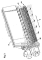
- the stowage shaft 23 is shown with a removal roller 24 in which all sections are needled.
- the stowage shaft 23 or the associated removal roller 24 is designed to supply a double strand.
- a portion of the extraction roller 24 (portions 24a-c) feeds a first strand with the tobacco mixture and the other portion (portions 24d-f) a second strand with the tobacco mixture.
- the front strand sections 24a, b and c and the rear strand sections 24d, e and f are provided.
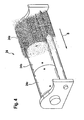
- the FIG. 4 is only the removal roller 24 for supplying a single strand shown.
- the section 24a that is, the first section seen in the strand direction S, is provided with a needle plate, while the sections 24b and c located further in the strand direction S are unwaddled. There is also the possibility that only the section 24b is needled. This can be advantageous in order to produce better mixing within the strand cross-section. Alternatively, only two of the three sections 24a to c or all sections 24a to c may be needled. In particular for the basis of the FIG. 4 illustrated construction of the removal roller 24, it is useful to limit the storage shaft 23 to the correspondingly needled work area of the removal roller 24 or provide for each section 24a to c a separate storage shaft 23. In the latter case, it is advantageous to separately control and / or regulate the storage bays 23, so that a shaft-specific supply of the individual sections 24a to c is ensured.
- feeding device 12 of the distributor device 10 comprises a metering drum 26, which like the input device 11 associated with Stowing shaft 14 opens into the common receiving space 16.
- the metering drum 26 is used for direct supply of the mixture component M 2 in the receiving space 16.
- the metering drum 26 is rotatably driven and provided with recesses 27 for receiving and delivering the mixture component M 2 .
- the metering drum 26 is suitable for supplying free-flowing mixture components M 2 .
- the troughs 27 are aligned axially in the strand direction S.
- the metering drum 26 may be formed as a single drum or multiple drum. For this purpose, the single drum can be divided in the axial direction. Furthermore, a plurality of individual drums can form the metering drum 26.
- the width of the metering drum 26 in the axial direction corresponds in one embodiment to the width of the removal roller 15. In other embodiments, the width of the metering drum 26 may differ from the width of the removal roller 15. In the event that several individual drums form the metering roller 26, each individual drum can be assigned its own drive 28, 29.
- the metering drum 26 is connected to a storage device 30.
- the memory device 30 itself can be used as a multiple memory for recording several Individual components (the mixture component M 2 ) may be formed.
- a scraper 31 is arranged, which ensures the uniform filling of all wells 27.
- the input of the mixture component M 1 via the input device 11 to the receiving space 16 is the same for all embodiments and proceeds in a known manner. From the outside, the mixture component M 1 is input to the distribution apparatus 10. The mixture component M 1 is received in a Speicheriepe 18 and continuously fed by means of the conveying element 19 to the sifter 13. In the sifter 13, the mixture component M 1 is spotted. In this case, non-processed parts (eg ribs) of shares to be processed (eg tobacco fibers) are separated. Only the parts to be processed are supplied to the stowage bay 14 by the air flow via the guide 20 and stowed in the stowage bay 14. The removal roller 15 meshes by rotation from the storage shaft 14, the mixing component M 1 and leads them with the aid of the impact roller 17 to the receiving space 16.
- a Speicheriepe 18 and continuously fed by means of the conveying element 19 to the sifter 13.
- non-processed parts eg ribs
- shares to be processed
- the mixture component M 2 can now also be supplied to the receiving space 16 in various ways according to the invention.
- the mixture component M 2 is taken up in a storage pond and fed to the storage shaft 23 by means of a conveying element.
- the mixture component M 2 is jammed.
- the removal roller 24 combs by rotation from the storage shaft 23, the mixture component M 2 and leads them with the aid of the impact roller 25 to the receiving space 16.
- the storage and promotion can also be done in other ways.
- the desired for strand production, final tobacco blend is thus produced only after the or each Stowage 14, 23 directly and directly before the strand formation.
- the storage compartments 14, 23 can have the same width, so that both mixing components M 1 and M 2 over the entire machine width, ie the full width of the shaft (in strand direction S) with correspondingly completely needled removal rollers 15, 24 can be added.
- the strand produced over the entire length and over the strand cross-section is evenly provided with two mixing components M 1 and M 2 . This means that the excess tobacco trimmed from the strand also contains both mixing components M 1 and M 2 .
- the stop shaft 23 may be narrower, so that the mixture component M 2, for example, falls only on the first two sections 24a and b or only on one of the two sections 24 a or b. This means that the tobacco mixture which was last stowed away, ie the furthest away from the suction belt transversely to the direction of the line S, now has only the mixture component M 1 . Since the excess tobacco is free of the mixture component M 2 (ie contains only the mixture component M 1 ), this excess tobacco can be returned to the input device 11 again.
- the supply of the mixture component M 2 via the metering drum 26 takes place accordingly.
- the mixture contains component M 2 sichtungskritica no play, the metering drum 26 can perform over the entire width of the pick roller 15, the mixture component m 2. If the mixture component M 2 is critical components, the or each individual component of the Mixing component M 2 only over a part of the width of the removal roller 15 is added.
Landscapes
- Manufacturing Of Cigar And Cigarette Tobacco (AREA)
Claims (15)
- Dispositif de répartition (10) destiné au chargement d'une machine de confection de boudins de cigarettes avec un mélange de tabac formé de plusieurs constituants de mélange, comprenant un dispositif d'introduction (11) pour introduire un premier constituant de mélange M1, un dispositif d'alimentation (12) pour amener un autre constituant de mélange M2, un trieur (13) pour séparer les fractions à traiter et à ne pas traiter du premier constituant de mélange M1, ainsi qu'une goulotte d'accumulation (14) disposée en aval du trieur (13), à laquelle est coordonné côté sortie un cylindre de prélèvement (15) destiné à transférer le constituant de mélange M1 trié dans le trieur (13) dans un espace de réception (16), le dispositif d'alimentation (12), au moins au nombre de un, ne constituant pas un dispositif de recyclage à l'intérieur du dispositif de répartition (10), caractérisé en ce que le dispositif d'alimentation (12) destiné à amener au moins un autre constituant de mélange M2 dans la direction de transport T1 du constituant de mélange M1, introduit via le dispositif d'introduction (11) et s'écoulant à travers le trieur (13), débouche en aval de la goulotte d'accumulation (14) directement dans l'espace de réception (16) de façon telle que le mélange de tabac formé des constituants de mélange M1 et M2 peut être obtenu au plus tôt dans l'espace de réception (16) commun.
- Dispositif selon la revendication 1, caractérisé en ce que l'espace de réception (16) en aval de la goulotte d'accumulation (14) présente au moins deux accès (21, 22) séparés, un accès (21) étant conçu et configuré pour introduire le constituant de mélange M1 trié dans le trieur (13) et un accès (22) pour introduire le constituant de mélange M2 non trié.
- Dispositif selon la revendication 1 ou 2, caractérisé en ce que le dispositif d'alimentation (12) présente au moins une goulotte d'accumulation (23) à laquelle est coordonné côté sortie un cylindre de prélèvement (24).
- Dispositif selon la revendication 3, caractérisé en ce que les goulottes d'accumulation (14, 23) ou les cylindres de prélèvement (15, 24), respectivement coordonnés à celle-ci, du dispositif d'introduction (11) et du dispositif d'alimentation (12) débouchent dans l'espace de réception (16) commun.
- Dispositif selon la revendication 3 ou 4, caractérisé en ce que les goulottes d'accumulation (14, 23) du dispositif d'introduction (11) d'une part et du dispositif d'alimentation (12) d'autre part sont situées côte à côte et de manière parallèle entre elles, vues dans la direction S du boudin.
- Dispositif selon l'une des revendications 3 à 5, caractérisé en ce que la goulotte d'accumulation (23) coordonnée au dispositif d'alimentation (12) est plus étroite dans la direction S du boudin que la goulotte d'accumulation (14) coordonnée au dispositif d'introduction (11).
- Dispositif selon l'une des revendications 1 à 6, caractérisé en ce que le dispositif d'alimentation (12) présente au moins deux goulottes d'accumulation (23), un cylindre de prélèvement (24) commun étant coordonné aux goulottes d'accumulation (23) du dispositif d'alimentation (12).
- Dispositif selon l'une des revendications 3 à 7, caractérisé en ce que le cylindre de prélèvement (24) de la ou de chaque goulotte d'accumulation (23) coordonnée au dispositif d'alimentation (12) est plus court en direction axiale que le cylindre de prélèvement (15) de la goulotte d'accumulation (14) associée au dispositif d'introduction (11).
- Dispositif selon l'une des revendications 3 à 8, caractérisé en ce que les cylindres de prélèvement (15, 24) sont conçus sous la forme de cylindres à aiguilles, le cylindre de prélèvement (24) de la ou de chaque goulotte d'accumulation (23) coordonnée au dispositif d'alimentation (12) n'étant pourvu d'aiguilles que sur une partie de la longueur en direction axiale tandis que le cylindre de prélèvement (15) de la goulotte d'accumulation (14) coordonnée au dispositif d'introduction (11) est pourvu d'aiguilles sur toute la longueur en direction axiale.
- Dispositif selon l'une des revendications 3 à 9, caractérisé en ce que le cylindre de prélèvement (24) des goulottes d'accumulation (23) coordonnées au dispositif d'alimentation (12) est divisé, dans la direction axiale, en plusieurs, de préférence en trois, tronçons, le premier tronçon (24a, d) vu dans la direction S du boudin et/ou le tronçon médian (24b, e) au choix étant pourvus d'aiguilles pour chaque boudin.
- Dispositif selon la revendication 1 ou 2, caractérisé en ce que le dispositif d'alimentation (12) comprend un tambour de dosage (26) qui, comme la goulotte d'accumulation (14) coordonnée au dispositif d'introduction (11), débouche dans l'espace de réception (16) commun.
- Dispositif selon la revendication 11, caractérisé en ce que le tambour de dosage (26) peut être entraîné en rotation et est pourvu d'auges (27) destinées à recevoir et délivrer des constituants de mélange M2 à écoulement libre.
- Dispositif selon la revendication 11 ou 12, caractérisé en ce que le tambour de dosage (26) est divisé en direction axiale et/ou est constitué de plusieurs tambours individuels.
- Dispositif selon l'une des revendications 11 à 13, caractérisé en ce que le tambour de dosage (26) est raccordé à un dispositif de stockage (30) d'un ou de plusieurs constituants individuels des constituants de mélange M2.
- Procédé de chargement d'une machine de confection de boudins de cigarettes avec un mélange de tabac formé de plusieurs constituants de mélange, comprenant les étapes suivantes :- introduction d'un premier constituant de mélange M1 au moyen d'un dispositif d'introduction (11) d'un dispositif de répartition (10),- tri du premier constituant de mélange M1 dans un trieur (13),- transfert du constituant de mélange M1 trié dans un espace de réception (16) au moyen d'un cylindre de prélèvement (15) coordonné à une goulotte d'accumulation (14),- amenée d'au moins un autre constituant de mélange M2, qui n'est pas un excédent de tabac à recycler, dans le dispositif de répartition au moyen d'un dispositif d'alimentation (12),caractérisé en ce que le mélange de tabac formé des constituants de mélange M1 et M2 est obtenu au plus tôt dans un espace de réception (16) commun en aval de la ou de chaque goulotte d'accumulation (14, 23).
Applications Claiming Priority (1)
| Application Number | Priority Date | Filing Date | Title |
|---|---|---|---|
| DE102009041030.9A DE102009041030B9 (de) | 2009-09-11 | 2009-09-11 | Verteilervorrichtung und Verfahren zum Beschicken einer Zigarettenstrangmaschine |
Publications (2)
| Publication Number | Publication Date |
|---|---|
| EP2311330A1 EP2311330A1 (fr) | 2011-04-20 |
| EP2311330B1 true EP2311330B1 (fr) | 2014-12-24 |
Family
ID=43569558
Family Applications (1)
| Application Number | Title | Priority Date | Filing Date |
|---|---|---|---|
| EP10075420.9A Active EP2311330B1 (fr) | 2009-09-11 | 2010-09-09 | Dispositif de répartition et procédé de chargement d'une machine à cigarettes |
Country Status (3)
| Country | Link |
|---|---|
| EP (1) | EP2311330B1 (fr) |
| CN (1) | CN102018283B (fr) |
| DE (1) | DE102009041030B9 (fr) |
Families Citing this family (5)
| Publication number | Priority date | Publication date | Assignee | Title |
|---|---|---|---|---|
| DE102012101024A1 (de) | 2012-02-08 | 2013-08-08 | Hauni Maschinenbau Ag | Vorrichtung und Verfahren zum Bilden mindestens eines Strangs der Tabak verarbeitenden Industrie sowie Verteilervorrichtung zum Beschicken einer Strangmaschine |
| DE102012109906A1 (de) * | 2012-10-17 | 2014-10-30 | Hauni Maschinenbau Ag | Verteilervorrichtung und Verfahren zum Beschicken einer Strangmaschine der Tabak verarbeitenden Industrie mit einem aus Fasermaterial bestehenden Produktstrom |
| DE102012109903A1 (de) * | 2012-10-17 | 2014-10-30 | Hauni Maschinenbau Ag | Verteilervorrichtung und Verfahren zum Beschicken einer Strangmaschine der Tabak verarbeitenden Industrie mit einem aus Fasermaterial bestehenden Produktstrom |
| CN103126067B (zh) * | 2013-02-28 | 2015-04-08 | 山东中烟工业有限责任公司 | 应用于卷烟机单机在线从剔除梗签中筛分出烟丝的装置 |
| CN105310105B (zh) * | 2015-12-04 | 2017-08-29 | 龙岩烟草工业有限责任公司 | 卷烟机供料系统的柔性送丝装置及方法 |
Family Cites Families (9)
| Publication number | Priority date | Publication date | Assignee | Title |
|---|---|---|---|---|
| CA1250204A (fr) | 1985-05-15 | 1989-02-21 | Rothmans Of Pall Mall Limited | Machines sans tremis pour la production de cigarettes |
| DE3624260A1 (de) * | 1985-08-08 | 1987-02-19 | Hauni Werke Koerber & Co Kg | Verfahren und vorrichtung zum bilden eines stranges aus tabak- oder dgl. fasern |
| DE3619579C2 (de) * | 1986-06-11 | 1995-05-18 | Hauni Werke Koerber & Co Kg | Vorrichtung zur gleichzeitigen Herstellung von zwei Endloszigarettensträngen |
| DE4035937A1 (de) | 1989-11-25 | 1991-05-29 | Hauni Werke Koerber & Co Kg | Verfahren und vorrichtung zum herstellen eines tabakstranges |
| IT1253915B (it) | 1991-12-17 | 1995-08-31 | Gd Spa | Unita' di alimentazione con separatore di particelle di tabacco per una macchina confezionatrice di sigarette |
| IT1304436B1 (it) | 1998-12-15 | 2001-03-19 | Gd Spa | Metodo e dispositivo per la formazione di un baco di sigarettaprovvisto di materiale additivo. |
| DE10007485A1 (de) * | 2000-02-18 | 2001-08-23 | Hauni Maschinenbau Ag | Verfahren und Vorrichtung zur Verwertung von Tabakstaub |
| ATE341953T1 (de) | 2003-01-28 | 2006-11-15 | Hauni Maschinenbau Ag | Verfahren insbesondere zum beschicken einer zigarettenstrangmaschine sowie verteilervorrichtung insbesondere zum durchführen des verfahrens |
| ITBO20030246A1 (it) | 2003-04-29 | 2004-10-30 | Gd Spa | Macchina confezionatrice di sigarette. |
-
2009
- 2009-09-11 DE DE102009041030.9A patent/DE102009041030B9/de not_active Expired - Fee Related
-
2010
- 2010-09-09 EP EP10075420.9A patent/EP2311330B1/fr active Active
- 2010-09-10 CN CN201010289034.9A patent/CN102018283B/zh not_active Expired - Fee Related
Also Published As
| Publication number | Publication date |
|---|---|
| DE102009041030B9 (de) | 2024-04-18 |
| EP2311330A1 (fr) | 2011-04-20 |
| DE102009041030B4 (de) | 2024-02-01 |
| DE102009041030A1 (de) | 2011-03-24 |
| CN102018283A (zh) | 2011-04-20 |
| CN102018283B (zh) | 2014-11-26 |
Similar Documents
| Publication | Publication Date | Title |
|---|---|---|
| EP1955604B1 (fr) | Dispositif et procédé destinés au remplissage de récipients à l'aide de produits en forme de tiges | |
| EP1364588B1 (fr) | Dispositif et procédé pour la formation d'au moins deux tiges de tabac dans une machine de fabrication de tige de tabac | |
| EP1847187B1 (fr) | Unité de préparation destinée à la préparation d'au moins une bande de filtre tout comme un dispositif doté d'au moins deux telles unités de préparation | |
| EP2311330B1 (fr) | Dispositif de répartition et procédé de chargement d'une machine à cigarettes | |
| DE2948272A1 (de) | Maehdrescher | |
| EP1952706A1 (fr) | Magasin de vidage et procédé de vidage de récipients remplis de produits en forme de tige, en particulier récipients en forme de colonne | |
| EP2659792A2 (fr) | Procédé et dispositif de rassemblement de groupes de segments de filtre | |
| DE69715008T2 (de) | Verfahren zur Abgabe eines Tabakstromes, Verteiler und Zigarettenherstellungsmaschine mit einem solchen Verteiler | |
| DE3142123A1 (de) | "verfahren zum bilden eines tabakstrangkerns und vorrichtung zur durchfuehrung des verfahrens" | |
| EP2505087B1 (fr) | Procédé et dispositif de fabrication de tiges dans l'industrie du traitement du tabac | |
| DE3937151A1 (de) | Beschickungsvorrichtung fuer eine doppelstrangmaschine der tabakverarbeitenden industrie | |
| DE102012109906A1 (de) | Verteilervorrichtung und Verfahren zum Beschicken einer Strangmaschine der Tabak verarbeitenden Industrie mit einem aus Fasermaterial bestehenden Produktstrom | |
| EP2721937A2 (fr) | Dispositif de distribution et procédé de garniture d'une machine à fabriquer des tiges de l'industrie de traitement du tabac avec un flux de produit constitué de matériau fibreux | |
| EP1442666B1 (fr) | Procédé en particulier pour alimenter une machine de fabrication de tige de tabac ainsi que distributeur en particulier pour la mise en oeuvre du procédé | |
| DE102015122807A1 (de) | Faserbearbeitungsanlage sowie Verfahren zum Öffnen und Mischen von Fasermaterial in einer Faserbearbeitungsanlage | |
| DE3937538C2 (de) | Verfahren und Maschine zur gleichzeitigen Herstellung von zwei kontinuierlichen Zigarettensträngen | |
| DE69205797T2 (de) | Ausrichtungsverfahren und -vorrichtung für einen Ausgabetrichter, insbesondere zum Ausgaben von Zigaretten. | |
| EP2653044B1 (fr) | Dispositif pour composer des groupes de segments de filtre | |
| DE102012101021B3 (de) | Verteilervorrichtung und Verfahren zum Beschicken einer Strangmaschine der Tabak verarbeitenden Industrie | |
| EP1529449A1 (fr) | Appareil pour séparer tabac et air, et dispositif et procédé pour la formation d'au moins deux tiges de tabac dans une machine de fabrication de tige de tabac | |
| DE3706008C2 (fr) | ||
| DE102010000677A1 (de) | Vorrichtung zur gleichzeitigen Herstellung von wenigstens zwei Faservliesen für die Herstellung von Filterstäben der Tabak verarbeitenden Industrie | |
| EP2353410A2 (fr) | Dispositif de séparation pour séparer un flux de produits à l'intérieur d'un dispositif de distribution | |
| EP2883462A1 (fr) | Dispositif de distribution et procédé de garniture d'une machine à fabriquer des tiges de l'industrie de traitement du tabac avec un flux de produit en matériau fibreux enrichi en additifs | |
| DE102024117861A1 (de) | Maschine der Tabak verarbeitenden Industrie, Verfahren zum Betreiben derselben und stabförmige Artikel |
Legal Events
| Date | Code | Title | Description |
|---|---|---|---|
| PUAI | Public reference made under article 153(3) epc to a published international application that has entered the european phase |
Free format text: ORIGINAL CODE: 0009012 |
|
| AK | Designated contracting states |
Kind code of ref document: A1 Designated state(s): AL AT BE BG CH CY CZ DE DK EE ES FI FR GB GR HR HU IE IS IT LI LT LU LV MC MK MT NL NO PL PT RO SE SI SK SM TR |
|
| AX | Request for extension of the european patent |
Extension state: BA ME RS |
|
| 17P | Request for examination filed |
Effective date: 20111017 |
|
| TPAC | Observations filed by third parties |
Free format text: ORIGINAL CODE: EPIDOSNTIPA |
|
| GRAP | Despatch of communication of intention to grant a patent |
Free format text: ORIGINAL CODE: EPIDOSNIGR1 |
|
| INTG | Intention to grant announced |
Effective date: 20140714 |
|
| GRAS | Grant fee paid |
Free format text: ORIGINAL CODE: EPIDOSNIGR3 |
|
| GRAA | (expected) grant |
Free format text: ORIGINAL CODE: 0009210 |
|
| AK | Designated contracting states |
Kind code of ref document: B1 Designated state(s): AL AT BE BG CH CY CZ DE DK EE ES FI FR GB GR HR HU IE IS IT LI LT LU LV MC MK MT NL NO PL PT RO SE SI SK SM TR |
|
| REG | Reference to a national code |
Ref country code: GB Ref legal event code: FG4D Free format text: NOT ENGLISH |
|
| REG | Reference to a national code |
Ref country code: CH Ref legal event code: EP |
|
| REG | Reference to a national code |
Ref country code: IE Ref legal event code: FG4D Free format text: LANGUAGE OF EP DOCUMENT: GERMAN |
|
| REG | Reference to a national code |
Ref country code: AT Ref legal event code: REF Ref document number: 702652 Country of ref document: AT Kind code of ref document: T Effective date: 20150115 |
|
| REG | Reference to a national code |
Ref country code: DE Ref legal event code: R096 Ref document number: 502010008547 Country of ref document: DE Effective date: 20150212 |
|
| REG | Reference to a national code |
Ref country code: NL Ref legal event code: T3 |
|
| PG25 | Lapsed in a contracting state [announced via postgrant information from national office to epo] |
Ref country code: NO Free format text: LAPSE BECAUSE OF FAILURE TO SUBMIT A TRANSLATION OF THE DESCRIPTION OR TO PAY THE FEE WITHIN THE PRESCRIBED TIME-LIMIT Effective date: 20150324 Ref country code: FI Free format text: LAPSE BECAUSE OF FAILURE TO SUBMIT A TRANSLATION OF THE DESCRIPTION OR TO PAY THE FEE WITHIN THE PRESCRIBED TIME-LIMIT Effective date: 20141224 Ref country code: LT Free format text: LAPSE BECAUSE OF FAILURE TO SUBMIT A TRANSLATION OF THE DESCRIPTION OR TO PAY THE FEE WITHIN THE PRESCRIBED TIME-LIMIT Effective date: 20141224 |
|
| REG | Reference to a national code |
Ref country code: LT Ref legal event code: MG4D |
|
| PG25 | Lapsed in a contracting state [announced via postgrant information from national office to epo] |
Ref country code: LV Free format text: LAPSE BECAUSE OF FAILURE TO SUBMIT A TRANSLATION OF THE DESCRIPTION OR TO PAY THE FEE WITHIN THE PRESCRIBED TIME-LIMIT Effective date: 20141224 Ref country code: HR Free format text: LAPSE BECAUSE OF FAILURE TO SUBMIT A TRANSLATION OF THE DESCRIPTION OR TO PAY THE FEE WITHIN THE PRESCRIBED TIME-LIMIT Effective date: 20141224 Ref country code: GR Free format text: LAPSE BECAUSE OF FAILURE TO SUBMIT A TRANSLATION OF THE DESCRIPTION OR TO PAY THE FEE WITHIN THE PRESCRIBED TIME-LIMIT Effective date: 20150325 Ref country code: SE Free format text: LAPSE BECAUSE OF FAILURE TO SUBMIT A TRANSLATION OF THE DESCRIPTION OR TO PAY THE FEE WITHIN THE PRESCRIBED TIME-LIMIT Effective date: 20141224 |
|
| PG25 | Lapsed in a contracting state [announced via postgrant information from national office to epo] |
Ref country code: CZ Free format text: LAPSE BECAUSE OF FAILURE TO SUBMIT A TRANSLATION OF THE DESCRIPTION OR TO PAY THE FEE WITHIN THE PRESCRIBED TIME-LIMIT Effective date: 20141224 Ref country code: EE Free format text: LAPSE BECAUSE OF FAILURE TO SUBMIT A TRANSLATION OF THE DESCRIPTION OR TO PAY THE FEE WITHIN THE PRESCRIBED TIME-LIMIT Effective date: 20141224 Ref country code: RO Free format text: LAPSE BECAUSE OF FAILURE TO SUBMIT A TRANSLATION OF THE DESCRIPTION OR TO PAY THE FEE WITHIN THE PRESCRIBED TIME-LIMIT Effective date: 20141224 Ref country code: SK Free format text: LAPSE BECAUSE OF FAILURE TO SUBMIT A TRANSLATION OF THE DESCRIPTION OR TO PAY THE FEE WITHIN THE PRESCRIBED TIME-LIMIT Effective date: 20141224 Ref country code: ES Free format text: LAPSE BECAUSE OF FAILURE TO SUBMIT A TRANSLATION OF THE DESCRIPTION OR TO PAY THE FEE WITHIN THE PRESCRIBED TIME-LIMIT Effective date: 20141224 |
|
| PG25 | Lapsed in a contracting state [announced via postgrant information from national office to epo] |
Ref country code: IS Free format text: LAPSE BECAUSE OF FAILURE TO SUBMIT A TRANSLATION OF THE DESCRIPTION OR TO PAY THE FEE WITHIN THE PRESCRIBED TIME-LIMIT Effective date: 20150424 Ref country code: PL Free format text: LAPSE BECAUSE OF FAILURE TO SUBMIT A TRANSLATION OF THE DESCRIPTION OR TO PAY THE FEE WITHIN THE PRESCRIBED TIME-LIMIT Effective date: 20141224 |
|
| REG | Reference to a national code |
Ref country code: DE Ref legal event code: R026 Ref document number: 502010008547 Country of ref document: DE |
|
| PLBI | Opposition filed |
Free format text: ORIGINAL CODE: 0009260 |
|
| PG25 | Lapsed in a contracting state [announced via postgrant information from national office to epo] |
Ref country code: DK Free format text: LAPSE BECAUSE OF FAILURE TO SUBMIT A TRANSLATION OF THE DESCRIPTION OR TO PAY THE FEE WITHIN THE PRESCRIBED TIME-LIMIT Effective date: 20141224 |
|
| PLAX | Notice of opposition and request to file observation + time limit sent |
Free format text: ORIGINAL CODE: EPIDOSNOBS2 |
|
| 26 | Opposition filed |
Opponent name: G.D S.P.A. Effective date: 20150924 |
|
| PLBB | Reply of patent proprietor to notice(s) of opposition received |
Free format text: ORIGINAL CODE: EPIDOSNOBS3 |
|
| PG25 | Lapsed in a contracting state [announced via postgrant information from national office to epo] |
Ref country code: SI Free format text: LAPSE BECAUSE OF FAILURE TO SUBMIT A TRANSLATION OF THE DESCRIPTION OR TO PAY THE FEE WITHIN THE PRESCRIBED TIME-LIMIT Effective date: 20141224 |
|
| PG25 | Lapsed in a contracting state [announced via postgrant information from national office to epo] |
Ref country code: LU Free format text: LAPSE BECAUSE OF FAILURE TO SUBMIT A TRANSLATION OF THE DESCRIPTION OR TO PAY THE FEE WITHIN THE PRESCRIBED TIME-LIMIT Effective date: 20150909 Ref country code: MC Free format text: LAPSE BECAUSE OF FAILURE TO SUBMIT A TRANSLATION OF THE DESCRIPTION OR TO PAY THE FEE WITHIN THE PRESCRIBED TIME-LIMIT Effective date: 20141224 |
|
| REG | Reference to a national code |
Ref country code: CH Ref legal event code: PL |
|
| GBPC | Gb: european patent ceased through non-payment of renewal fee |
Effective date: 20150909 |
|
| REG | Reference to a national code |
Ref country code: IE Ref legal event code: MM4A |
|
| REG | Reference to a national code |
Ref country code: FR Ref legal event code: ST Effective date: 20160531 |
|
| RAP2 | Party data changed (patent owner data changed or rights of a patent transferred) |
Owner name: HAUNI MASCHINENBAU GMBH |
|
| REG | Reference to a national code |
Ref country code: DE Ref legal event code: R081 Ref document number: 502010008547 Country of ref document: DE Owner name: HAUNI MASCHINENBAU GMBH, DE Free format text: FORMER OWNER: HAUNI MASCHINENBAU AG, 21033 HAMBURG, DE |
|
| PG25 | Lapsed in a contracting state [announced via postgrant information from national office to epo] |
Ref country code: CH Free format text: LAPSE BECAUSE OF NON-PAYMENT OF DUE FEES Effective date: 20150930 Ref country code: GB Free format text: LAPSE BECAUSE OF NON-PAYMENT OF DUE FEES Effective date: 20150909 Ref country code: IE Free format text: LAPSE BECAUSE OF NON-PAYMENT OF DUE FEES Effective date: 20150909 Ref country code: LI Free format text: LAPSE BECAUSE OF NON-PAYMENT OF DUE FEES Effective date: 20150930 |
|
| PG25 | Lapsed in a contracting state [announced via postgrant information from national office to epo] |
Ref country code: FR Free format text: LAPSE BECAUSE OF NON-PAYMENT OF DUE FEES Effective date: 20150930 |
|
| REG | Reference to a national code |
Ref country code: NL Ref legal event code: PD Owner name: HAUNI MASCHINENBAU GMBH; DE Free format text: DETAILS ASSIGNMENT: VERANDERING VAN EIGENAAR(S), VERANDERING VAN DE JURIDISCHE ENTITEIT; FORMER OWNER NAME: HAUNI MASCHINENBAU AG Effective date: 20160928 |
|
| REG | Reference to a national code |
Ref country code: AT Ref legal event code: MM01 Ref document number: 702652 Country of ref document: AT Kind code of ref document: T Effective date: 20150909 |
|
| PG25 | Lapsed in a contracting state [announced via postgrant information from national office to epo] |
Ref country code: AT Free format text: LAPSE BECAUSE OF NON-PAYMENT OF DUE FEES Effective date: 20150909 |
|
| PLCK | Communication despatched that opposition was rejected |
Free format text: ORIGINAL CODE: EPIDOSNREJ1 |
|
| STAA | Information on the status of an ep patent application or granted ep patent |
Free format text: STATUS: THE PATENT HAS BEEN GRANTED |
|
| PG25 | Lapsed in a contracting state [announced via postgrant information from national office to epo] |
Ref country code: MT Free format text: LAPSE BECAUSE OF FAILURE TO SUBMIT A TRANSLATION OF THE DESCRIPTION OR TO PAY THE FEE WITHIN THE PRESCRIBED TIME-LIMIT Effective date: 20141224 |
|
| APBM | Appeal reference recorded |
Free format text: ORIGINAL CODE: EPIDOSNREFNO |
|
| APBP | Date of receipt of notice of appeal recorded |
Free format text: ORIGINAL CODE: EPIDOSNNOA2O |
|
| PG25 | Lapsed in a contracting state [announced via postgrant information from national office to epo] |
Ref country code: HU Free format text: LAPSE BECAUSE OF FAILURE TO SUBMIT A TRANSLATION OF THE DESCRIPTION OR TO PAY THE FEE WITHIN THE PRESCRIBED TIME-LIMIT; INVALID AB INITIO Effective date: 20100909 Ref country code: SM Free format text: LAPSE BECAUSE OF FAILURE TO SUBMIT A TRANSLATION OF THE DESCRIPTION OR TO PAY THE FEE WITHIN THE PRESCRIBED TIME-LIMIT Effective date: 20141224 Ref country code: BG Free format text: LAPSE BECAUSE OF FAILURE TO SUBMIT A TRANSLATION OF THE DESCRIPTION OR TO PAY THE FEE WITHIN THE PRESCRIBED TIME-LIMIT Effective date: 20141224 |
|
| APAH | Appeal reference modified |
Free format text: ORIGINAL CODE: EPIDOSCREFNO |
|
| PG25 | Lapsed in a contracting state [announced via postgrant information from national office to epo] |
Ref country code: CY Free format text: LAPSE BECAUSE OF FAILURE TO SUBMIT A TRANSLATION OF THE DESCRIPTION OR TO PAY THE FEE WITHIN THE PRESCRIBED TIME-LIMIT Effective date: 20141224 |
|
| PG25 | Lapsed in a contracting state [announced via postgrant information from national office to epo] |
Ref country code: BE Free format text: LAPSE BECAUSE OF NON-PAYMENT OF DUE FEES Effective date: 20150930 |
|
| APBQ | Date of receipt of statement of grounds of appeal recorded |
Free format text: ORIGINAL CODE: EPIDOSNNOA3O |
|
| PG25 | Lapsed in a contracting state [announced via postgrant information from national office to epo] |
Ref country code: TR Free format text: LAPSE BECAUSE OF FAILURE TO SUBMIT A TRANSLATION OF THE DESCRIPTION OR TO PAY THE FEE WITHIN THE PRESCRIBED TIME-LIMIT Effective date: 20141224 |
|
| PG25 | Lapsed in a contracting state [announced via postgrant information from national office to epo] |
Ref country code: MK Free format text: LAPSE BECAUSE OF FAILURE TO SUBMIT A TRANSLATION OF THE DESCRIPTION OR TO PAY THE FEE WITHIN THE PRESCRIBED TIME-LIMIT Effective date: 20141224 |
|
| PG25 | Lapsed in a contracting state [announced via postgrant information from national office to epo] |
Ref country code: PT Free format text: LAPSE BECAUSE OF FAILURE TO SUBMIT A TRANSLATION OF THE DESCRIPTION OR TO PAY THE FEE WITHIN THE PRESCRIBED TIME-LIMIT Effective date: 20141224 |
|
| PG25 | Lapsed in a contracting state [announced via postgrant information from national office to epo] |
Ref country code: AL Free format text: LAPSE BECAUSE OF FAILURE TO SUBMIT A TRANSLATION OF THE DESCRIPTION OR TO PAY THE FEE WITHIN THE PRESCRIBED TIME-LIMIT Effective date: 20141224 |
|
| APAH | Appeal reference modified |
Free format text: ORIGINAL CODE: EPIDOSCREFNO |
|
| REG | Reference to a national code |
Ref country code: DE Ref legal event code: R100 Ref document number: 502010008547 Country of ref document: DE |
|
| APBU | Appeal procedure closed |
Free format text: ORIGINAL CODE: EPIDOSNNOA9O |
|
| PLBN | Opposition rejected |
Free format text: ORIGINAL CODE: 0009273 |
|
| STAA | Information on the status of an ep patent application or granted ep patent |
Free format text: STATUS: OPPOSITION REJECTED |
|
| 27O | Opposition rejected |
Effective date: 20220211 |
|
| POAG | Date of filing of petition for review recorded |
Free format text: ORIGINAL CODE: EPIDOSNPRV3 |
|
| POAH | Number of petition for review recorded |
Free format text: ORIGINAL CODE: EPIDOSNPRV1 |
|
| POAI | Petitioner in petition for review recorded |
Free format text: ORIGINAL CODE: EPIDOSNPRV2 |
|
| REG | Reference to a national code |
Ref country code: DE Ref legal event code: R081 Ref document number: 502010008547 Country of ref document: DE Owner name: KOERBER TECHNOLOGIES GMBH, DE Free format text: FORMER OWNER: HAUNI MASCHINENBAU GMBH, 21033 HAMBURG, DE |
|
| REG | Reference to a national code |
Ref country code: NL Ref legal event code: HC Owner name: KOERBER TECHNOLOGIES GMBH; DE Free format text: DETAILS ASSIGNMENT: CHANGE OF OWNER(S), CHANGE OF OWNER(S) NAME; FORMER OWNER NAME: HAUNI MASCHINENBAU GMBH Effective date: 20221020 |
|
| P01 | Opt-out of the competence of the unified patent court (upc) registered |
Effective date: 20230621 |
|
| PGFP | Annual fee paid to national office [announced via postgrant information from national office to epo] |
Ref country code: NL Payment date: 20230921 Year of fee payment: 14 |
|
| PLAB | Opposition data, opponent's data or that of the opponent's representative modified |
Free format text: ORIGINAL CODE: 0009299OPPO |
|
| R26 | Opposition filed (corrected) |
Opponent name: G.D S.P.A. Effective date: 20150924 |
|
| REG | Reference to a national code |
Ref country code: NL Ref legal event code: MM Effective date: 20241001 |
|
| POAD | Information related to date of filing of petition for review deleted |
Free format text: ORIGINAL CODE: EPIDOSDPRV3 |
|
| POAK | Decision taken: petition for review obviously unsubstantiated |
Free format text: ORIGINAL CODE: 0009255 |
|
| PG25 | Lapsed in a contracting state [announced via postgrant information from national office to epo] |
Ref country code: NL Free format text: LAPSE BECAUSE OF NON-PAYMENT OF DUE FEES Effective date: 20241001 |
|
| PRVN | Petition for review not allowed |
Free format text: PETITION FOR REVIEW OBVIOUSLY INADMISSABLE (NOT DEEMED TO BE FILED) OR SIMULTANEOUSLY OBVIOUSLY INADMISSABLE AND OBVIOUSLY UNSUBSTANTIATED Effective date: 20250401 |
|
| PGFP | Annual fee paid to national office [announced via postgrant information from national office to epo] |
Ref country code: IT Payment date: 20250929 Year of fee payment: 16 |
|
| PGFP | Annual fee paid to national office [announced via postgrant information from national office to epo] |
Ref country code: DE Payment date: 20251002 Year of fee payment: 16 |