EP2311613A2 - Nachfüllbehälter - Google Patents
Nachfüllbehälter Download PDFInfo
- Publication number
- EP2311613A2 EP2311613A2 EP10008838A EP10008838A EP2311613A2 EP 2311613 A2 EP2311613 A2 EP 2311613A2 EP 10008838 A EP10008838 A EP 10008838A EP 10008838 A EP10008838 A EP 10008838A EP 2311613 A2 EP2311613 A2 EP 2311613A2
- Authority
- EP
- European Patent Office
- Prior art keywords
- staple
- saw
- toothed
- toothed portion
- locking
- Prior art date
- Legal status (The legal status is an assumption and is not a legal conclusion. Google has not performed a legal analysis and makes no representation as to the accuracy of the status listed.)
- Granted
Links
Images



Classifications
-
- B—PERFORMING OPERATIONS; TRANSPORTING
- B27—WORKING OR PRESERVING WOOD OR SIMILAR MATERIAL; NAILING OR STAPLING MACHINES IN GENERAL
- B27F—DOVETAILED WORK; TENONS; SLOTTING MACHINES FOR WOOD OR SIMILAR MATERIAL; NAILING OR STAPLING MACHINES
- B27F7/00—Nailing or stapling; Nailed or stapled work
- B27F7/17—Stapling machines
- B27F7/38—Staple feeding devices
Definitions
- the present invention relates to a refill case in which staples for stapling paper sheets are accommodated in straight states before formation.
- An electric stapler is so constituted as to be capable of attaching and detaching a staple cartridge.
- the staple cartridge is so constituted as to be capable of attaching and detaching a refill case in which staple-sheets, each of which is formed by connecting straight staple members with an adhesive in a sheet shape, are accommodated in a stacking manner.
- the refill case includes a staple pressing member which is arranged inside an accommodating part and presses a top of the accommodated staple-sheets, and return-preventing claws formed at left and right ends of the staple pressing member.
- These return-preventing claws are provided so as to be capable of locking in locking saw-toothed portions (return-preventing grooves), each having a saw-toothed cross section, which are formed in left and right inner walls of the accommodating part and extending along a stacking direction of the staple-sheets (Patent Document 1).
- the staple cartridge includes a feeding path which is connected to a leading-out port from which the lowermost staple-sheet in the accommodating part of the refill case is led out, and a feeding means which leads out the lowermost staple-sheet in turn to the feeding path and feeds the led-out staple-sheet to a drive-out part side.
- a feeding pawl is formed obliquely upward.
- the feeding pawl is so constituted as to feed out the staple-sheet in a state locked to a groove between front and rear staples on a bottom of the lowermost staple-sheet. Accordingly, when the staple-sheet is moved in the feeding direction, the feeding pawl acts so as to stick up the staple-sheet obliquely upward [Patent Document 1] US2008/0083805
- a feeding mechanism for feeding a staple-sheet to a drive-out part such the structure that a feeding pawl is arranged obliquely to the staple-sheet, a leading end of a feeding pawl is engaged with a groove between adjacent staple members, and the feeding pawl feeds the staple-sheet so as to stick up the staple-sheet obliquely upward so that the leading end is disengaged, there is no problem in case that the number of the staple-sheets is large and the whole weight of the staple-sheets is heavy.
- the return-preventing claw is liable to unlock from the locking saw-toothed portion due to large vibration. Further, in case that the return-preventing claw has unlocked, since the staple-sheet floats greatly, there is possibility that the adhesive bonding the staple members peels off at a part of the staple-sheet, the staple-sheet breaks and the connected staple members are separated. Further, also when the stapler is operated or an attaching table to which the stapler is attached moves, there is possibility that the vibration is produced in the refill case and the similar disadvantage is produced.
- One or more embodiments of the invention provide a refill case which can make a moving amount of a staple pressing member even when the staple pressing member unlocks from a return-preventing groove smaller than a pitch between teeth of return-preventing groove.
- a refill case is provided with: an accommodating part (2) in which staple-sheets (1) , each of which is formed by connecting straight staple members in a sheet shape, are stacked and accommodated; a staple pressing member (4) which is arranged inside the accommodating part (2) and configured to press a top of the staple-sheets (1) in the accommodating part; a right locking saw-toothed portion (6a, 6b) formed in a right inner wall (2b) of the accommodating part (2) and having a saw-toothed shape with a plurality of peaks (35, 35a, 35b) and a plurality of troughs (37) alternatively arranged with each other along a stacking direction of the staple-sheets (1); a left locking saw-toothed portion (6a, 6b) formed in a left inner wall (2b) of the accommodating part (2) and having a saw-toothed shape with a plurality of peaks (35, 35a, 35b) and a plurality of troughs
- the right return-preventing claw positions in the same position in the stacking direction with the left return preventing claw.
- a phase of the saw-toothed shape of the right locking saw-toothed portion is shifted from a phase of the saw-toothed shape of the left locking saw-toothed portion.
- the phase of the saw-toothed shape of the right locking saw-toothed portion may be shifted by 1/2 pitches from the phase of the saw-toothed shape of the left locking saw-toothed portion.
- the locking saw-toothed portions each having a saw-toothed cross section are formed in the right and left inner walls of the accommodating part for the staple-sheets along a stacking direction of the staple-sheets, the return-preventing claws are formed at both ends of the staple pressing member in a bilaterally symmetric manner, which can engage with the locking saw-toothed portions, and the phases of the right and left locking saw-toothed portions are shifted with each other. Therefore, when one claw of the staple pressing member unlocks from a peak of one corresponding locking saw-toothed portion, the other claw locks to a peak of the other locking saw-toothed portion.
- the staple pressing member Since the peak of the locking saw-toothed portion from the claw has unlocked is shifted from the peak of the locking saw-toothed portion to which the claw has newly locked, the staple pressing member also moves by only a shifted amount. Thus, even in case that the interval between the peaks is the same in the locking saw-toothed portions on the both sides, the moving amount of the staple pressing member can be suppressed to the shifted amount. Accordingly, in case that the refill case is formed of synthetic resin, even in case that the formation is difficult because the pitch of the locking saw-toothed portion is so small as to be beyond a forming limit, it is possible to suppress the moving amount of the staple pressing member to the shifted amount. Therefore, it is possible to prevent the staple-sheets from floating and to prevent the occurrence of poor feeding.
- a refill case is provided with: an accommodating part (2) in which staple-sheets (1) , each of which is formed by connecting straight staple members in a sheet shape, are stacked and accommodated; a staple pressing member (4) which is arranged inside the accommodating part (2) and configured to press a top of the staple-sheets (1) in the accommodating part; a right locking saw-toothed portion (6a, 6b) formed in a right inner wall (2b) of the accommodating part (2) and having a saw-toothed shape with a plurality of peaks (35, 35a, 35b) and a plurality of troughs (37) alternatively arranged with each other along a stacking direction of the staple-sheets (1) ; a left locking saw-toothed portion (6a, 6b) formed in a left inner wall (2b) of the accommodating part (2) and having a saw-toothed shape with a plurality of peaks (35, 35a, 35b) and a plurality of troughs (37) alternatively arranged with each other along
- a phase of the saw-toothed shape of the right locking saw-toothed portion is the same with a phase of the saw-toothed shape of the left locking saw-toothed portion.
- the right locking saw-toothed portion is formed in a position shifted from the left locking saw-toothed portion in the stacking direction.
- the right locking saw-toothed portion may be formed in a position shifted by 1/2 pitches of said saw-toothed shape in the stacking direction from the left locking saw-toothed portion.
- the right and left locking saw-toothed portions are arranged in the same positions of the right and left inner walls in the same phases, and the right and left return-preventing claws are formed so as to be shifted with each other. Therefore, the advantage similar to that in the first aspect can be obtained.
- Fig. 1 is a perspective view of a refill case made of synthetic resin
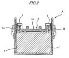
- Fig. 2 is a longitudinal sectional view of the refill case.
- a reference character A represents the refill case made of synthetic resin.
- the refill case A includes an accommodating part 2 in which staple-sheets 1 are accommodated in a stacking manner, and a staple pressing member 4 made of synthetic resin, which is arranged at a top of the staple-sheets 1 accommodated in the accommodating part 2.
- the staple pressing member 4 is used in order to prevent the accommodated staple-sheets 1 from getting out of an upper opening portion of the refill case A due to vibration in the conveying time or in the stapling time.
- standing pieces 5a each having a return-preventing claw 5 at its leading end, and projections 19 protruding laterally.
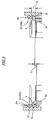
- the return-preventing claws 5 are formed in a bilaterally symmetric manner. As shown in Fig. 3 , the return-preventing claw 5 is formed so as to protrude from the leading end of the standing piece 5a to the outside.
- the staple-sheet 1 is formed by connecting straight staple members in a sheet-shape with an adhesive.
- the staple member is formed in U-shape inside an electric stapler C described later and thereafter driven out.
- a leading-out port 3 from which the lowermost staple-sheet 1 is led out.
- an opening part (not shown) is formed, fromwhich a lower surface of a lowermost staple-sheet is exposed.
- opening grooves 29 are formed in the up-down direction.
- locking saw-toothed portions 6a and 6b having saw-toothed shapes with a plurality of peaks and a plurality of troughs alternatively arranged with each other are formed along an up and down direction (stacking direction of staple-sheets).
- a size of the locking saw-toothed portion 6a is the same as that of the locking saw-toothed portion 6b, a phase of the locking saw-toothed portion 6a is shifted from a phase of the locking saw-toothed portion 6b by 1/2 pitches as described later.
- the left and right return-preventing claws 5 are arranged in the same height positions of the left and right sidewalls 2b.
- the plural staple-sheets 1 are accommodated, being stacked in multistage.
- the staple pressing member 4 is arranged, which presses the staple-sheets 1 from the upside so that the staple-sheets 1 are not shaky.
- the projections 19 of the staple pressing member 4 are protruded outward from the opening grooves 29 formed on the both sides of the accommodating part 2.
- the return-preventing claws 5 of the staple pressing member 4 when the staple pressing member 4 descends, get over the locking saw-toothed portions 6a, 6b formed in the inner surface of the accommodating part 2; and when the staple pressing member attempts to ascend, lock to the locking saw-toothed portions 6a, 6b, thereby to prevent the staple pressing member from floating.
- an engaging part 10 and a locking hole 11 are formed respectively.
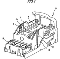
- a reference character B is a staple cartridge for attaching and detaching the refill case A, in which an attachment part 12 for attaching the refill case A is formed.
- an attachment part 12 for attaching the refill case A is formed at the front upper portion of the attachment part 12, a pressing part 13 for the refill case A is formed being protruded inward.
- a locking piece 15 having a locking jaw 14 is formed downward.
- a staple guide part 18 is formed protrusively. At the lower portion of the staple guide part 18, a feeding path 20 for the staple-sheet 1 is formed. A front end of the feeding path 20 opens to a drive-out part 23 formed penetratingly in the up-down direction.
- the engaging part 10 of the front wall 8a of the refill case A is obliquely forward pushed into the lower portion of the pressing part 13 of the attachment part 12.
- the refill case A is downward moved rotationally around the leading end of the engaging part 10, and the locking jaw 14 of the locking piece 15 of the attachment part 12 is locked into the locking hole 11 of the refill case A.
- the staple cartridge B to which the refill case A has been attached is constituted so as to be detachably attached to the electric stapler C as shown in Figs. 6 and 7 .
- the electric stapler C is mounted on a paper handing device used as a paper finisher provided in a back stage of an image forming apparatus such as a copying machine or a printer.
- a stapling table 26 is provided; below the stapling table 26, a not-shown staple forming and driving part is provided; and above the stapling table 26, a clincher drive part 27 is provided swingably in the up and down direction.
- the forming and driving part is a section which forms staples fed out sequentially from the staple cartridge B and drives out the formed staple, in which there is provided a forming and driving mechanism which includes a forming plate for forming a staple in the U-shape and a driver for driving out the formed staple.
- the clincher drive part 27 includes, at a leading end of a drive link 28 provided swingably for the stapler body 25, a movable clincher which bends leg portions of the staple driven out by the driver and penetrating the paper sheets. Since both the forming and driving mechanism and the clincher drive part are known, the description of them is omitted.
- push bars 30 are provided on both sides of the back portion of the electric stapler C.
- the back portion of the push bar 30 is attached pivotally by a pivot 34 provided for the stapler body 25.
- an extension spring 31 is arranged, which has a front end 32 locked to the staple cartridge B and a back end 33 locked to a back end upper portion of the push bar 30. Accordingly, by the action of the extension spring 31, the front end of the push bar 30 is always energized so as to move downward.
- the projection 19 of the staple pressing member 4 of the refill case engages with the lower surface of the push bar 30 as shown in Fig. 7 .
- the projection 19 is pushed up to the uppermost portion of the push bar 30. Accordingly, since the staple pressing member 4 is pressed downward by the push bar 30, the staple-sheets 1 in the refill case A is held down by the staple pressing member 4.
- the lowermost staple-sheet 1 in the refill case A is previously fed to the feeding path 20 in the staple cartridge B shown in Fig. 5 by a feeding means (not shown), and formed in the U-shape by the forming plate, and thereafter a leading staple is supplied to the drive-out part 23.
- the paper sheets are prepared and placed on the stapling table 26 in Fig. 6 , and a switch is turned on.
- the drive link 28 swings downward and clamps the paper sheets between the stapling table 26 and the clincher drive part 27.
- the formed staple is driven out upward by the driver (simultaneously, the next staple is formed), and the driven staple penetrates the paper sheets and protrudes from the paper sheets.
- the protruded staple portion is bent by the movable clincher along the face of the paper sheets, and stapling is completed.
- the drive link 28 returns and moves to the upper waiting position.
- the position of the uppermost staple-sheet lowers. As the position of the staple-sheet lowers, the return-preventing claw 5 of the staple pressing member 4 gets over the locking saw-toothed portions 6a, 6b by the push bar 30 and moves down. Therefore, pressing of the staple-sheets 1 is secured.
- the right and left locking saw-toothed portions 6a and 6b formed in the both sidewalls 2b of the refill case A are different from each other in phase.
- the left and right locking saw-toothed portions 6a and 6b are out of phase with each other by 1/2 pitches. Namely, although the interval of a pitch (interval between peaks (teeth) or interval between troughs) H is the same in the locking saw-toothed portions 6a and 6b, phases of the saw-tooth shapes of the left and right locking saw-toothed portions 6a and 6b are shifted with each other by an interval h of 1/2 pitches.
- the right and left return-preventing claws 5 of the staple pressing member 4 are in a state where when one return-preventing claw 5 locks to a peak (tooth) 35 of one locking saw-toothed portion 6a, the other return-preventing claw 5 does not lock to a peak 35 of the other locking saw-toothed portion 6.
- the other return-preventing claw 5 locks to a peak 35b of the other locking saw-toothed portion 6b. Since the peak 35a of the locking saw-toothed portion 6 from which one return-preventing claw has unlocked is out of phase with the peak 35b of the locking saw-toothed portion 6 to which the other return-preventing claw has newly locked by only 1/2 pitches, the staple pressing member moves by only 1/2 pitches. Thus, since the moving amount of the staple pressing member is suppressed by 1/2 pitches of the locking saw-toothed portion 6, the return-preventing claw 5 is difficult to lock from the locking saw-toothed portion 6a.
- the feeding pawl 36 when the staple-sheet 1 is fed by the feeding pawl 36, the floating amount of the staple-sheet 1 when the staple-sheet 1 is stuck up is only the 1/2 pitches of the locking saw-toothed portion 6. Therefore, in the feeding time, the feeding pawl 36 is prevented from unlocking from the lower surface of the staple-sheet 1, and the staple-sheet is sent surely in the predetermined direction.
- the refill case A is formed of synthetic resin
- the pitch of the locking saw-toothed portion 6a, 6b is so small as to be beyond a machining limit
- the return-preventing claw 5 which has locked from the peak 35a of one locking saw-toothed portion 6a is located between a peak 35c of the locking saw-toothed portion 6 on the peak 35a and a trough 37.
- the return-preventing claw unlocks from the locking saw-toothed portion 6 in the conveying time of the refill case, since the vibration is great, there is also possible that the adhesive which bonds staple members to each other will peel off at a part of the staple-sheet, the staple-sheet will be broken, and the staple members will be disconnected from each other.
- the right and left locking saw-toothed portions may be formed to have the same phase with each other and the right and left return-preventing claws may be arranged to be shifted with each other by 1/2 pitches of the saw-toothed shape.
Landscapes
- Engineering & Computer Science (AREA)
- Mechanical Engineering (AREA)
- Life Sciences & Earth Sciences (AREA)
- Forests & Forestry (AREA)
- Portable Nailing Machines And Staplers (AREA)
- Dovetailed Work, And Nailing Machines And Stapling Machines For Wood (AREA)
- Folding Of Thin Sheet-Like Materials, Special Discharging Devices, And Others (AREA)
Applications Claiming Priority (1)
| Application Number | Priority Date | Filing Date | Title |
|---|---|---|---|
| JP2009240010A JP4915443B2 (ja) | 2009-10-19 | 2009-10-19 | リフィルケース |
Publications (3)
| Publication Number | Publication Date |
|---|---|
| EP2311613A2 true EP2311613A2 (de) | 2011-04-20 |
| EP2311613A3 EP2311613A3 (de) | 2011-07-27 |
| EP2311613B1 EP2311613B1 (de) | 2012-08-22 |
Family
ID=43533047
Family Applications (1)
| Application Number | Title | Priority Date | Filing Date |
|---|---|---|---|
| EP10008838A Active EP2311613B1 (de) | 2009-10-19 | 2010-08-25 | Nachfüllbehälter |
Country Status (4)
| Country | Link |
|---|---|
| US (1) | US9242392B2 (de) |
| EP (1) | EP2311613B1 (de) |
| JP (1) | JP4915443B2 (de) |
| CN (1) | CN102059873B (de) |
Cited By (2)
| Publication number | Priority date | Publication date | Assignee | Title |
|---|---|---|---|---|
| EP3482895A1 (de) * | 2017-11-10 | 2019-05-15 | Max Co., Ltd. | Nachfüllung |
| CN109968856A (zh) * | 2017-11-10 | 2019-07-05 | 美克司株式会社 | 替换件 |
Families Citing this family (3)
| Publication number | Priority date | Publication date | Assignee | Title |
|---|---|---|---|---|
| JP5954029B2 (ja) * | 2011-10-13 | 2016-07-20 | マックス株式会社 | ステープル用リフィル |
| JP5924180B2 (ja) * | 2011-10-13 | 2016-05-25 | マックス株式会社 | ステープル用リフィル |
| JP5954028B2 (ja) | 2011-10-13 | 2016-07-20 | マックス株式会社 | ステープル用リフィル |
Citations (1)
| Publication number | Priority date | Publication date | Assignee | Title |
|---|---|---|---|---|
| US20080083805A1 (en) | 2004-10-20 | 2008-04-10 | Kiichi Haramiishi | Staple Container For Electric Stapler |
Family Cites Families (13)
| Publication number | Priority date | Publication date | Assignee | Title |
|---|---|---|---|---|
| DE69406507T2 (de) * | 1993-08-04 | 1998-03-05 | Max Co Ltd | Kassette für eine elektrische Klammermaschine |
| US5584471A (en) * | 1995-10-27 | 1996-12-17 | Xerox Corporation | Reproduction machine having a user clearable convenience stapler assembly |
| JP3620351B2 (ja) * | 1999-07-06 | 2005-02-16 | マックス株式会社 | 電動ステープラー |
| US6899258B2 (en) * | 2001-08-09 | 2005-05-31 | Max Co., Ltd. | Cartridge |
| JP4089211B2 (ja) * | 2001-11-19 | 2008-05-28 | マックス株式会社 | ステープルカートリッジ |
| JP2003145506A (ja) * | 2001-11-15 | 2003-05-20 | Max Co Ltd | ステープルパック |
| EP2196289B1 (de) * | 2003-02-07 | 2013-04-10 | MAX Kabushiki Kaisha | Klammernachfüllvorrichtung |
| ATE483562T1 (de) * | 2003-02-14 | 2010-10-15 | Max Co Ltd | Heftvorrichtung |
| JP4042154B2 (ja) * | 2003-08-29 | 2008-02-06 | マックス株式会社 | カートリッジ |
| JP4438545B2 (ja) * | 2004-07-15 | 2010-03-24 | マックス株式会社 | ステープラにおけるステープルカートリッジの着脱機構 |
| JP4232716B2 (ja) * | 2004-09-06 | 2009-03-04 | マックス株式会社 | ステープラ用カートリッジ |
| JP4844074B2 (ja) * | 2005-10-07 | 2011-12-21 | マックス株式会社 | 電動ステープラ |
| JP5242132B2 (ja) * | 2007-11-06 | 2013-07-24 | キヤノンファインテック株式会社 | ステープラ |
-
2009
- 2009-10-19 JP JP2009240010A patent/JP4915443B2/ja active Active
-
2010
- 2010-08-25 EP EP10008838A patent/EP2311613B1/de active Active
- 2010-08-26 US US12/869,062 patent/US9242392B2/en active Active
- 2010-10-19 CN CN201010517403.5A patent/CN102059873B/zh active Active
Patent Citations (1)
| Publication number | Priority date | Publication date | Assignee | Title |
|---|---|---|---|---|
| US20080083805A1 (en) | 2004-10-20 | 2008-04-10 | Kiichi Haramiishi | Staple Container For Electric Stapler |
Cited By (14)
| Publication number | Priority date | Publication date | Assignee | Title |
|---|---|---|---|---|
| EP3482895A1 (de) * | 2017-11-10 | 2019-05-15 | Max Co., Ltd. | Nachfüllung |
| CN109968856A (zh) * | 2017-11-10 | 2019-07-05 | 美克司株式会社 | 替换件 |
| CN110143079A (zh) * | 2017-11-10 | 2019-08-20 | 美克司株式会社 | 替换件 |
| EP3549735A1 (de) * | 2017-11-10 | 2019-10-09 | Max Co., Ltd. | Nachfüllung |
| EP3725480A1 (de) * | 2017-11-10 | 2020-10-21 | Max Co., Ltd. | Nachfüllung |
| US10821626B2 (en) | 2017-11-10 | 2020-11-03 | Max Co., Ltd. | Refill |
| EP3753695A1 (de) * | 2017-11-10 | 2020-12-23 | Max Co., Ltd. | Klammernachfüllung |
| CN109968856B (zh) * | 2017-11-10 | 2021-05-07 | 美克司株式会社 | 替换件 |
| CN110143079B (zh) * | 2017-11-10 | 2021-05-07 | 美克司株式会社 | 替换件 |
| US11077580B2 (en) | 2017-11-10 | 2021-08-03 | Max Co., Ltd. | Refill |
| CN113306323A (zh) * | 2017-11-10 | 2021-08-27 | 美克司株式会社 | 替换件 |
| CN113306322A (zh) * | 2017-11-10 | 2021-08-27 | 美克司株式会社 | 替换件 |
| CN113306322B (zh) * | 2017-11-10 | 2023-05-05 | 美克司株式会社 | 替换件 |
| US12097635B2 (en) | 2017-11-10 | 2024-09-24 | Max Co., Ltd. | Staple refill |
Also Published As
| Publication number | Publication date |
|---|---|
| JP2011084017A (ja) | 2011-04-28 |
| JP4915443B2 (ja) | 2012-04-11 |
| US9242392B2 (en) | 2016-01-26 |
| US20110089216A1 (en) | 2011-04-21 |
| CN102059873A (zh) | 2011-05-18 |
| EP2311613A3 (de) | 2011-07-27 |
| CN102059873B (zh) | 2014-07-09 |
| EP2311613B1 (de) | 2012-08-22 |
Similar Documents
| Publication | Publication Date | Title |
|---|---|---|
| EP2311613B1 (de) | Nachfüllbehälter | |
| KR100709993B1 (ko) | 전동 호치키스 | |
| US10688680B2 (en) | Staple-refill | |
| EP2311614B1 (de) | Nachfüllbehälter und Klammermagazin | |
| CN101898351B (zh) | 订书钉盒 | |
| US9498873B2 (en) | Stapler | |
| US8251272B2 (en) | Stapler | |
| JP4513443B2 (ja) | ステープラにおけるステープルのガイド機構 | |
| JP5861488B2 (ja) | ステープラ | |
| JP4300397B2 (ja) | ステープル脚ガイド機構 | |
| CN100548587C (zh) | 订书钉装订匣 | |
| JP4465832B2 (ja) | 電動ステープラ | |
| JP3674433B2 (ja) | 電動ホッチキス用カートリッジ | |
| US20060186168A1 (en) | Stapler | |
| JP3692881B2 (ja) | 電動ホッチキス | |
| JP6620485B2 (ja) | ステープラ | |
| JP3697989B2 (ja) | 電動ホッチキス | |
| JP4096552B2 (ja) | ステープルカートリッジ | |
| JP2005014416A (ja) | 電動ステープラーのステープル供給機構 |
Legal Events
| Date | Code | Title | Description |
|---|---|---|---|
| PUAI | Public reference made under article 153(3) epc to a published international application that has entered the european phase |
Free format text: ORIGINAL CODE: 0009012 |
|
| AK | Designated contracting states |
Kind code of ref document: A2 Designated state(s): AL AT BE BG CH CY CZ DE DK EE ES FI FR GB GR HR HU IE IS IT LI LT LU LV MC MK MT NL NO PL PT RO SE SI SK SM TR |
|
| AX | Request for extension of the european patent |
Extension state: BA ME RS |
|
| PUAL | Search report despatched |
Free format text: ORIGINAL CODE: 0009013 |
|
| AK | Designated contracting states |
Kind code of ref document: A3 Designated state(s): AL AT BE BG CH CY CZ DE DK EE ES FI FR GB GR HR HU IE IS IT LI LT LU LV MC MK MT NL NO PL PT RO SE SI SK SM TR |
|
| AX | Request for extension of the european patent |
Extension state: BA ME RS |
|
| 17P | Request for examination filed |
Effective date: 20111123 |
|
| GRAP | Despatch of communication of intention to grant a patent |
Free format text: ORIGINAL CODE: EPIDOSNIGR1 |
|
| GRAS | Grant fee paid |
Free format text: ORIGINAL CODE: EPIDOSNIGR3 |
|
| GRAA | (expected) grant |
Free format text: ORIGINAL CODE: 0009210 |
|
| AK | Designated contracting states |
Kind code of ref document: B1 Designated state(s): AL AT BE BG CH CY CZ DE DK EE ES FI FR GB GR HR HU IE IS IT LI LT LU LV MC MK MT NL NO PL PT RO SE SI SK SM TR |
|
| REG | Reference to a national code |
Ref country code: GB Ref legal event code: FG4D |
|
| REG | Reference to a national code |
Ref country code: CH Ref legal event code: EP |
|
| REG | Reference to a national code |
Ref country code: IE Ref legal event code: FG4D |
|
| REG | Reference to a national code |
Ref country code: AT Ref legal event code: REF Ref document number: 571715 Country of ref document: AT Kind code of ref document: T Effective date: 20120915 |
|
| REG | Reference to a national code |
Ref country code: DE Ref legal event code: R096 Ref document number: 602010002336 Country of ref document: DE Effective date: 20121018 |
|
| REG | Reference to a national code |
Ref country code: NL Ref legal event code: T3 |
|
| REG | Reference to a national code |
Ref country code: SE Ref legal event code: TRGR |
|
| REG | Reference to a national code |
Ref country code: AT Ref legal event code: MK05 Ref document number: 571715 Country of ref document: AT Kind code of ref document: T Effective date: 20120822 |
|
| REG | Reference to a national code |
Ref country code: LT Ref legal event code: MG4D Effective date: 20120822 |
|
| PG25 | Lapsed in a contracting state [announced via postgrant information from national office to epo] |
Ref country code: HR Free format text: LAPSE BECAUSE OF FAILURE TO SUBMIT A TRANSLATION OF THE DESCRIPTION OR TO PAY THE FEE WITHIN THE PRESCRIBED TIME-LIMIT Effective date: 20120822 Ref country code: FI Free format text: LAPSE BECAUSE OF FAILURE TO SUBMIT A TRANSLATION OF THE DESCRIPTION OR TO PAY THE FEE WITHIN THE PRESCRIBED TIME-LIMIT Effective date: 20120822 Ref country code: AT Free format text: LAPSE BECAUSE OF FAILURE TO SUBMIT A TRANSLATION OF THE DESCRIPTION OR TO PAY THE FEE WITHIN THE PRESCRIBED TIME-LIMIT Effective date: 20120822 Ref country code: NO Free format text: LAPSE BECAUSE OF FAILURE TO SUBMIT A TRANSLATION OF THE DESCRIPTION OR TO PAY THE FEE WITHIN THE PRESCRIBED TIME-LIMIT Effective date: 20121122 Ref country code: LT Free format text: LAPSE BECAUSE OF FAILURE TO SUBMIT A TRANSLATION OF THE DESCRIPTION OR TO PAY THE FEE WITHIN THE PRESCRIBED TIME-LIMIT Effective date: 20120822 Ref country code: IS Free format text: LAPSE BECAUSE OF FAILURE TO SUBMIT A TRANSLATION OF THE DESCRIPTION OR TO PAY THE FEE WITHIN THE PRESCRIBED TIME-LIMIT Effective date: 20121222 |
|
| PG25 | Lapsed in a contracting state [announced via postgrant information from national office to epo] |
Ref country code: BE Free format text: LAPSE BECAUSE OF FAILURE TO SUBMIT A TRANSLATION OF THE DESCRIPTION OR TO PAY THE FEE WITHIN THE PRESCRIBED TIME-LIMIT Effective date: 20120822 Ref country code: PT Free format text: LAPSE BECAUSE OF FAILURE TO SUBMIT A TRANSLATION OF THE DESCRIPTION OR TO PAY THE FEE WITHIN THE PRESCRIBED TIME-LIMIT Effective date: 20121224 Ref country code: SI Free format text: LAPSE BECAUSE OF FAILURE TO SUBMIT A TRANSLATION OF THE DESCRIPTION OR TO PAY THE FEE WITHIN THE PRESCRIBED TIME-LIMIT Effective date: 20120822 Ref country code: LV Free format text: LAPSE BECAUSE OF FAILURE TO SUBMIT A TRANSLATION OF THE DESCRIPTION OR TO PAY THE FEE WITHIN THE PRESCRIBED TIME-LIMIT Effective date: 20120822 Ref country code: GR Free format text: LAPSE BECAUSE OF FAILURE TO SUBMIT A TRANSLATION OF THE DESCRIPTION OR TO PAY THE FEE WITHIN THE PRESCRIBED TIME-LIMIT Effective date: 20121123 |
|
| PG25 | Lapsed in a contracting state [announced via postgrant information from national office to epo] |
Ref country code: MC Free format text: LAPSE BECAUSE OF NON-PAYMENT OF DUE FEES Effective date: 20120831 |
|
| PG25 | Lapsed in a contracting state [announced via postgrant information from national office to epo] |
Ref country code: CZ Free format text: LAPSE BECAUSE OF FAILURE TO SUBMIT A TRANSLATION OF THE DESCRIPTION OR TO PAY THE FEE WITHIN THE PRESCRIBED TIME-LIMIT Effective date: 20120822 Ref country code: EE Free format text: LAPSE BECAUSE OF FAILURE TO SUBMIT A TRANSLATION OF THE DESCRIPTION OR TO PAY THE FEE WITHIN THE PRESCRIBED TIME-LIMIT Effective date: 20120822 Ref country code: RO Free format text: LAPSE BECAUSE OF FAILURE TO SUBMIT A TRANSLATION OF THE DESCRIPTION OR TO PAY THE FEE WITHIN THE PRESCRIBED TIME-LIMIT Effective date: 20120822 Ref country code: ES Free format text: LAPSE BECAUSE OF FAILURE TO SUBMIT A TRANSLATION OF THE DESCRIPTION OR TO PAY THE FEE WITHIN THE PRESCRIBED TIME-LIMIT Effective date: 20121203 Ref country code: DK Free format text: LAPSE BECAUSE OF FAILURE TO SUBMIT A TRANSLATION OF THE DESCRIPTION OR TO PAY THE FEE WITHIN THE PRESCRIBED TIME-LIMIT Effective date: 20120822 |
|
| REG | Reference to a national code |
Ref country code: IE Ref legal event code: MM4A |
|
| PG25 | Lapsed in a contracting state [announced via postgrant information from national office to epo] |
Ref country code: IT Free format text: LAPSE BECAUSE OF FAILURE TO SUBMIT A TRANSLATION OF THE DESCRIPTION OR TO PAY THE FEE WITHIN THE PRESCRIBED TIME-LIMIT Effective date: 20120822 Ref country code: PL Free format text: LAPSE BECAUSE OF FAILURE TO SUBMIT A TRANSLATION OF THE DESCRIPTION OR TO PAY THE FEE WITHIN THE PRESCRIBED TIME-LIMIT Effective date: 20120822 Ref country code: SK Free format text: LAPSE BECAUSE OF FAILURE TO SUBMIT A TRANSLATION OF THE DESCRIPTION OR TO PAY THE FEE WITHIN THE PRESCRIBED TIME-LIMIT Effective date: 20120822 |
|
| PLBE | No opposition filed within time limit |
Free format text: ORIGINAL CODE: 0009261 |
|
| STAA | Information on the status of an ep patent application or granted ep patent |
Free format text: STATUS: NO OPPOSITION FILED WITHIN TIME LIMIT |
|
| 26N | No opposition filed |
Effective date: 20130523 |
|
| PG25 | Lapsed in a contracting state [announced via postgrant information from national office to epo] |
Ref country code: IE Free format text: LAPSE BECAUSE OF NON-PAYMENT OF DUE FEES Effective date: 20120825 Ref country code: BG Free format text: LAPSE BECAUSE OF FAILURE TO SUBMIT A TRANSLATION OF THE DESCRIPTION OR TO PAY THE FEE WITHIN THE PRESCRIBED TIME-LIMIT Effective date: 20121122 |
|
| REG | Reference to a national code |
Ref country code: DE Ref legal event code: R097 Ref document number: 602010002336 Country of ref document: DE Effective date: 20130523 |
|
| PG25 | Lapsed in a contracting state [announced via postgrant information from national office to epo] |
Ref country code: MT Free format text: LAPSE BECAUSE OF FAILURE TO SUBMIT A TRANSLATION OF THE DESCRIPTION OR TO PAY THE FEE WITHIN THE PRESCRIBED TIME-LIMIT Effective date: 20120822 Ref country code: AL Free format text: LAPSE BECAUSE OF FAILURE TO SUBMIT A TRANSLATION OF THE DESCRIPTION OR TO PAY THE FEE WITHIN THE PRESCRIBED TIME-LIMIT Effective date: 20120822 Ref country code: CY Free format text: LAPSE BECAUSE OF FAILURE TO SUBMIT A TRANSLATION OF THE DESCRIPTION OR TO PAY THE FEE WITHIN THE PRESCRIBED TIME-LIMIT Effective date: 20120822 |
|
| PG25 | Lapsed in a contracting state [announced via postgrant information from national office to epo] |
Ref country code: TR Free format text: LAPSE BECAUSE OF FAILURE TO SUBMIT A TRANSLATION OF THE DESCRIPTION OR TO PAY THE FEE WITHIN THE PRESCRIBED TIME-LIMIT Effective date: 20120822 |
|
| PG25 | Lapsed in a contracting state [announced via postgrant information from national office to epo] |
Ref country code: SM Free format text: LAPSE BECAUSE OF FAILURE TO SUBMIT A TRANSLATION OF THE DESCRIPTION OR TO PAY THE FEE WITHIN THE PRESCRIBED TIME-LIMIT Effective date: 20120822 Ref country code: LU Free format text: LAPSE BECAUSE OF NON-PAYMENT OF DUE FEES Effective date: 20120825 |
|
| PG25 | Lapsed in a contracting state [announced via postgrant information from national office to epo] |
Ref country code: HU Free format text: LAPSE BECAUSE OF FAILURE TO SUBMIT A TRANSLATION OF THE DESCRIPTION OR TO PAY THE FEE WITHIN THE PRESCRIBED TIME-LIMIT Effective date: 20100825 |
|
| REG | Reference to a national code |
Ref country code: CH Ref legal event code: PL |
|
| PG25 | Lapsed in a contracting state [announced via postgrant information from national office to epo] |
Ref country code: LI Free format text: LAPSE BECAUSE OF NON-PAYMENT OF DUE FEES Effective date: 20140831 Ref country code: CH Free format text: LAPSE BECAUSE OF NON-PAYMENT OF DUE FEES Effective date: 20140831 |
|
| PG25 | Lapsed in a contracting state [announced via postgrant information from national office to epo] |
Ref country code: MK Free format text: LAPSE BECAUSE OF FAILURE TO SUBMIT A TRANSLATION OF THE DESCRIPTION OR TO PAY THE FEE WITHIN THE PRESCRIBED TIME-LIMIT Effective date: 20120822 |
|
| REG | Reference to a national code |
Ref country code: FR Ref legal event code: PLFP Year of fee payment: 7 |
|
| REG | Reference to a national code |
Ref country code: FR Ref legal event code: PLFP Year of fee payment: 8 |
|
| PGFP | Annual fee paid to national office [announced via postgrant information from national office to epo] |
Ref country code: NL Payment date: 20170712 Year of fee payment: 8 |
|
| PGFP | Annual fee paid to national office [announced via postgrant information from national office to epo] |
Ref country code: SE Payment date: 20170810 Year of fee payment: 8 |
|
| REG | Reference to a national code |
Ref country code: FR Ref legal event code: PLFP Year of fee payment: 9 |
|
| REG | Reference to a national code |
Ref country code: SE Ref legal event code: EUG |
|
| REG | Reference to a national code |
Ref country code: NL Ref legal event code: MM Effective date: 20180901 |
|
| PG25 | Lapsed in a contracting state [announced via postgrant information from national office to epo] |
Ref country code: SE Free format text: LAPSE BECAUSE OF NON-PAYMENT OF DUE FEES Effective date: 20180826 |
|
| PG25 | Lapsed in a contracting state [announced via postgrant information from national office to epo] |
Ref country code: NL Free format text: LAPSE BECAUSE OF NON-PAYMENT OF DUE FEES Effective date: 20180901 |
|
| PGFP | Annual fee paid to national office [announced via postgrant information from national office to epo] |
Ref country code: DE Payment date: 20250702 Year of fee payment: 16 |
|
| PGFP | Annual fee paid to national office [announced via postgrant information from national office to epo] |
Ref country code: GB Payment date: 20250703 Year of fee payment: 16 |
|
| PGFP | Annual fee paid to national office [announced via postgrant information from national office to epo] |
Ref country code: FR Payment date: 20250703 Year of fee payment: 16 |