EP2312152A2 - Vorrichtung und Verfahren zur Manipulation eines Bauteils einer Windturbine - Google Patents
Vorrichtung und Verfahren zur Manipulation eines Bauteils einer Windturbine Download PDFInfo
- Publication number
- EP2312152A2 EP2312152A2 EP10186470A EP10186470A EP2312152A2 EP 2312152 A2 EP2312152 A2 EP 2312152A2 EP 10186470 A EP10186470 A EP 10186470A EP 10186470 A EP10186470 A EP 10186470A EP 2312152 A2 EP2312152 A2 EP 2312152A2
- Authority
- EP
- European Patent Office
- Prior art keywords
- blade
- wind turbine
- blade members
- blade member
- support
- Prior art date
- Legal status (The legal status is an assumption and is not a legal conclusion. Google has not performed a legal analysis and makes no representation as to the accuracy of the status listed.)
- Withdrawn
Links
- 238000000034 method Methods 0.000 title description 11
- 238000012423 maintenance Methods 0.000 description 9
- 230000004075 alteration Effects 0.000 description 1
- 230000005611 electricity Effects 0.000 description 1
- 238000006467 substitution reaction Methods 0.000 description 1
Images




Classifications
-
- F—MECHANICAL ENGINEERING; LIGHTING; HEATING; WEAPONS; BLASTING
- F03—MACHINES OR ENGINES FOR LIQUIDS; WIND, SPRING, OR WEIGHT MOTORS; PRODUCING MECHANICAL POWER OR A REACTIVE PROPULSIVE THRUST, NOT OTHERWISE PROVIDED FOR
- F03D—WIND MOTORS
- F03D80/00—Details, components or accessories not provided for in groups F03D1/00 - F03D17/00
- F03D80/50—Maintenance or repair
-
- F—MECHANICAL ENGINEERING; LIGHTING; HEATING; WEAPONS; BLASTING
- F05—INDEXING SCHEMES RELATING TO ENGINES OR PUMPS IN VARIOUS SUBCLASSES OF CLASSES F01-F04
- F05B—INDEXING SCHEME RELATING TO WIND, SPRING, WEIGHT, INERTIA OR LIKE MOTORS, TO MACHINES OR ENGINES FOR LIQUIDS COVERED BY SUBCLASSES F03B, F03D AND F03G
- F05B2230/00—Manufacture
- F05B2230/60—Assembly methods
- F05B2230/61—Assembly methods using auxiliary equipment for lifting or holding
-
- F—MECHANICAL ENGINEERING; LIGHTING; HEATING; WEAPONS; BLASTING
- F05—INDEXING SCHEMES RELATING TO ENGINES OR PUMPS IN VARIOUS SUBCLASSES OF CLASSES F01-F04
- F05B—INDEXING SCHEME RELATING TO WIND, SPRING, WEIGHT, INERTIA OR LIKE MOTORS, TO MACHINES OR ENGINES FOR LIQUIDS COVERED BY SUBCLASSES F03B, F03D AND F03G
- F05B2230/00—Manufacture
- F05B2230/80—Repairing, retrofitting or upgrading methods
-
- Y—GENERAL TAGGING OF NEW TECHNOLOGICAL DEVELOPMENTS; GENERAL TAGGING OF CROSS-SECTIONAL TECHNOLOGIES SPANNING OVER SEVERAL SECTIONS OF THE IPC; TECHNICAL SUBJECTS COVERED BY FORMER USPC CROSS-REFERENCE ART COLLECTIONS [XRACs] AND DIGESTS
- Y02—TECHNOLOGIES OR APPLICATIONS FOR MITIGATION OR ADAPTATION AGAINST CLIMATE CHANGE
- Y02E—REDUCTION OF GREENHOUSE GAS [GHG] EMISSIONS, RELATED TO ENERGY GENERATION, TRANSMISSION OR DISTRIBUTION
- Y02E10/00—Energy generation through renewable energy sources
- Y02E10/70—Wind energy
- Y02E10/72—Wind turbines with rotation axis in wind direction
-
- Y—GENERAL TAGGING OF NEW TECHNOLOGICAL DEVELOPMENTS; GENERAL TAGGING OF CROSS-SECTIONAL TECHNOLOGIES SPANNING OVER SEVERAL SECTIONS OF THE IPC; TECHNICAL SUBJECTS COVERED BY FORMER USPC CROSS-REFERENCE ART COLLECTIONS [XRACs] AND DIGESTS
- Y02—TECHNOLOGIES OR APPLICATIONS FOR MITIGATION OR ADAPTATION AGAINST CLIMATE CHANGE
- Y02P—CLIMATE CHANGE MITIGATION TECHNOLOGIES IN THE PRODUCTION OR PROCESSING OF GOODS
- Y02P70/00—Climate change mitigation technologies in the production process for final industrial or consumer products
- Y02P70/50—Manufacturing or production processes characterised by the final manufactured product
-
- Y—GENERAL TAGGING OF NEW TECHNOLOGICAL DEVELOPMENTS; GENERAL TAGGING OF CROSS-SECTIONAL TECHNOLOGIES SPANNING OVER SEVERAL SECTIONS OF THE IPC; TECHNICAL SUBJECTS COVERED BY FORMER USPC CROSS-REFERENCE ART COLLECTIONS [XRACs] AND DIGESTS
- Y10—TECHNICAL SUBJECTS COVERED BY FORMER USPC
- Y10S—TECHNICAL SUBJECTS COVERED BY FORMER USPC CROSS-REFERENCE ART COLLECTIONS [XRACs] AND DIGESTS
- Y10S416/00—Fluid reaction surfaces, i.e. impellers
- Y10S416/06—Supports for natural fluid current motors
-
- Y—GENERAL TAGGING OF NEW TECHNOLOGICAL DEVELOPMENTS; GENERAL TAGGING OF CROSS-SECTIONAL TECHNOLOGIES SPANNING OVER SEVERAL SECTIONS OF THE IPC; TECHNICAL SUBJECTS COVERED BY FORMER USPC CROSS-REFERENCE ART COLLECTIONS [XRACs] AND DIGESTS
- Y10—TECHNICAL SUBJECTS COVERED BY FORMER USPC
- Y10T—TECHNICAL SUBJECTS COVERED BY FORMER US CLASSIFICATION
- Y10T29/00—Metal working
- Y10T29/49—Method of mechanical manufacture
- Y10T29/49316—Impeller making
- Y10T29/49318—Repairing or disassembling
Definitions
- the subject matter disclosed herein relates generally to wind turbines and, more particularly, to an apparatus and method for servicing a component of a wind turbine.
- Wind generators convert energy provided by air currents into electricity.
- the air currents rotate large rotor blades or propellers that are mounted in nacelles at the top of a tower.
- the blades spin a rotor relative to a stator to generate an electrical current.
- the rate of rotation is controlled by varying blade pitch as well as through the use of various braking systems.
- the blade pitch is adjusted to spill wind energy in order to limit rotational speed.
- the braking system is employed to further prevent the blades from achieving high rotational speeds.
- the blade pitch is adjusted in order to capture as much wind energy as possible.
- a wind turbine includes a tower member having a first end portion that extends to a second end portion, a yaw system rotatably mounted to the second end portion of the tower member, and a wind energy collection system operatively coupled to the yaw system.
- the wind energy collection system includes a central hub and a plurality of blade members. Each of the plurality of blade members includes a root end portion operatively coupled to the hub, a tip portion that is cantilevered from the hub, and an intermediate portion.
- the wind turbine further includes a component manipulating system operatively coupled between at least one of the plurality of blade members and the tower member.
- the component manipulating system includes a first blade member support structure including a first end pivotally connected relative to the tower member that extends to a second end operatively coupled to the one of the plurality of blade members, and a winching system operatively connected to the one of the plurality of blade members and the tower member.
- the winching system is selectively operated to shift the one of the plurality of blade members relative to the tower member in order to enable serving of the wind turbine.
- a method of servicing a wind turbine includes supporting a portion of one of a plurality of blade members through a blade member support structure operatively coupled to a wind turbine tower member member, disconnecting the one of the plurality of blade members from a central hub, and lowering the one of the plurality of blade members axially relative to the tower member.
- a wind turbine component manipulating system includes a blade member support structure including a first end that extends to a second end. The first end is configured and disposed to pivotally connected to a wind turbine tower member and the second end is configured and disposed to operatively connect to one of a plurality of wind turbine blade members.
- the component manipulating system further includes a winching system. The winching system is configured and disposed to operatively connect between the one of the plurality of wind turbine blade members and the wind turbine tower member.
- Wind turbine 2 can be readily supported upon land or, at sea in order to capture wind currents that are converted into electrical power.
- wind turbine 2 includes a tower member 4 having a first end portion 6 that extends to a second end portion 8 through an intermediate portion 10.
- Wind turbine 2 further includes a yaw system/nacelle 12 that is positioned at a second end portion 8 of tower member 4.
- yaw system 12 rotates about an axis 13 defined by tower member 4.
- Wind turbine 2 is further shown to include a wind energy collection system 14 operatively coupled to yaw system 12.
- Wind energy collection system 14 includes a central hub 16 having attached thereto a plurality of blade members 20-22. Blade members 20-22 collectively rotate in response to wind currents. Blade members 20-22 are also individually rotatable to adjust pitch in order to capture as much energy as possible from the wind currents. In addition, blade members 20-22 are selectively positionable through rotation of yaw system 12 in order to face prevailing wind currents.
- blade member 20 includes a root portion 26 that extends to a tip portion 27 through an intermediate portion 28. Root portion 26 is operatively coupled to central hub 16. Similarly, blade member 21 includes a root portion 30 that extends to a tip portion 31 through an intermediate portion 32. Likewise, blade member 22 includes a root portion 34 that extends to a tip portion 35 through an intermediate portion 36. As discussed above, blade members 20-22 rotate in response to wind currents. The rotation of blade members 20-22 is coupled to a generator (not shown) arranged within the yaw system 12. The generator transforms energy from the wind currents to electrical energy. Over time, it is necessary to move, shift and/or manipulate components of the wind turbine in order to perform various maintenance tasks on wind energy collection system 14. Toward that end, wind turbine 2 includes a component manipulating system 46.
- component manipulating system 46 includes a first blade member support structure 54 having a first support member 56, a second support member 57 and a third support member 58.
- First support member 56 includes a first end portion 60 that extends to a second end portion 61 through an intermediate portion 62.
- First end portion 60 is pivotally mounted to tower member 4 through a mounting member 65.
- second end portion 61 is pivotally mounted to root portion 34 of blade member 22 through a mounting element 66.
- mounting member 65 and mounting element 66 are shown fixedly secured to tower member 4 and blade member 22, respectively.
- First support member 56 is also shown to include an extensible member 69. Extensible member 69 is selectively positionable to adjust a longitudinal length of first support member 56.
- second support member 57 includes a first end portion (not shown) that extends to a second end portion (also not shown) through an intermediate portion 74.
- First end portion of second support member 57 is pivotally mounted to tower member 4 through a mounting member (also not shown) while second end portion of second support member 57 is pivotally mounted to root portion 34 of blade member 32 through a mounting element (not shown).
- second support member 57 includes an extensible member 77.
- third support member 58 includes a first end portion 81 that is mounted to first end portion 60 of first support member 56. First end portion 81 extends to a second end portion 82 through an intermediate portion 83. Second end portion 82 is connected to the second end of second support member 57. In this manner, third support member 58 provides structural support and enhances stability of blade member support structure 54.
- component manipulating system 46 also includes a second blade member support structure 93.
- Second blade member support structure 93 includes a first support element 96, a second support element 97, and a third support element 98.
- Second blade member support structure 93 further includes a block member 104 having a first block element 106 and a second block element 107.
- First and second block elements 106 and 107 are detachably mounted to intermediate portion 36 of blade member 22.
- block member 104 could vary without departing from the scope of the invention.
- First support element 96 includes a first end section 111 that extends to a second end section 112 through an intermediate section 113.
- First end section 111 is pivotally mounted to tower member 4 through a mounting member 116.
- Second end section 112 of first support element 96 is pivotally mounted to block member 104.
- first support element 96 includes an extensible member 117.
- second support element 96 includes a first end section (not shown) that extends to a second end section (not shown) through an intermediate section 121.
- Second support element 97 also includes an extensible member (not shown).
- third support element 98 includes a first end section 128 that extends to a second end section 129 through an intermediate section 130.
- First end section 128 is connected to first end section 111 of first support element 96 while second end section 129 is connected to the second end section of second support element 97.
- third support element 98 provides structural support and stability to second blade member support structure 93.
- third support element 98 could include an extensible member that enhances connectivity between first end section 111 and the second end section of second support element 97.
- first and second blade member support structures 54 and 93 could include, for example rigid platforms that pivot relative to the tower. The platforms could include adjustment systems that are employed to manipulate blade members 20-22 as well as facilitate human access to the various locations on wind turbine 2.
- component manipulating system 46 includes a winching system 141.
- Winching system 141 includes a first cable 143 and a second cable 144.
- First and second cables 143, 144 extend between first blade member support structure 54 and second blade member support structure 93.
- First cable 143 extends between first end portion 60 of first support member 56 and second end section 112 of first support element 96.
- second cable 144 extends between the first end section (not shown) of second support member 57 and the second end portion (not shown) of second support element 96.
- Winching system 141 also includes an operating system (not shown) that is selectively operated to lower blade member 22 relative to hub 16.
- first and second cables 143 and 144 are connected to, for example, a pulley system, a drum system or the like arranged at second end portion 8 of tower member 4. With this arrangement, first and second cables 143 and 144 are extended and/or retracted in order to allow blade member 22 to pivot about first and second blade member support structures 54 and 93 as will be discussed more fully below.
- winching system 141 could include a dedicated attachment point provided on tower member 4 or nacelle 12.
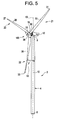
- blade member 22 is loosened from central hub 16 as shown in FIG. 4 .
- Cables 143 and 144 are extended to selectively lower blade member 22.
- blade member 22 pivots about first and second blade member supports structures 54 and 93.
- yaw system 12 pivots wind energy collection system 14 relative to tower member 4.
- central hub 16 is now clear of blade member 22.
- a bearing such as shown as 149, is selectively removed and lowered from central hub 16.
- yaw system 12 After a replacement bearing 149 is installed, and yaw system 12 is pivoted back to position central hub 14 adjacent to blade member 22.
- a pitch system (not shown) may also be operated to aide in final alignment of blade member 22, replacement bearing 149 and hub 16.
- cables 143 and 144 are retracted to selectively raise blade member 22 back to position.
- blade member 22 Once in position, blade member 22 is tightened and blade member support structures 54 and 93 are either removed from tower member 4 or utilized to service an additional blade member.
- component manipulating system 160 includes a first blade member support structure 166 and a second blade member support structure (not shown) similar to that described above in connection with component manipulating system 46.
- First blade member support structure 166 includes a first blade member support element 174 and second blade member support element 175.
- First blade member support element 174 is mounted to blade member 20 while second blade member support element 175 is mounted to blade member 21.
- first blade member support element 174 includes a first support rod 180, a second support rod 181, and a third support rod 182.
- First support rod 180 includes a first end 185 mounted to blade member 20 that extends to a second end 186.
- second support rod 181 includes a first end (not shown) mounted to blade member 22, which extends to a second end 189.
- third support rod 182 includes a first end 191 coupled to blade member 22 that extends to a second end 192.
- Each of the second ends 186, 189 and 192 of first, second and third support rods 180-182 are collectively joined by a linking member 194.
- First end 185 of first support rod 180 and the second end (not shown) of second support rode 181 are connected to blade member 20 through a first strap element 197. More specifically, first end 185 of first support rod 180 is connected to a first buckle 198 connected to first strap element 197 while the second end (not shown) of second support rod 181 is connected to a second buckle (also not shown) coupled to strap element 197. First end 191 of third support rod 182 is connected to a second strap element 202 through a buckle 203. With this arrangement, each of the first, second and third support rods 180-182 are cantilevered from blade member 20.
- second blade member support element 175 includes a first support rod 210, a second support rod 211, and a third support rod 212.
- First support rod 210 includes a first end 214 that is operatively coupled to blade member 21 and that extends to a second end 215.
- second support rod 211 includes a first end 217 that is operatively coupled to blade member 21 and that extends to a second end 218.
- Third support rod 212 includes a first end 220 also coupled to blade member 21 and which extends to a second end 221. Each of the second ends 215, 218 and 221 are joined by a linking member 223.
- first ends 214 and 217 of first and second support rods are connected to a first strap element 226 through corresponding first and second buckles 227 and 228.
- First end 220 of third support rod 212 is coupled to a second strap element 230 through a buckle 231.
- Strap elements 197, 202, 226, and 230 provide a removable interface between first and second blade member support elements 174 and 175 and corresponding ones of the blade members 20-22. With this arrangement, first and second blade member support elements 174 and 175 are utilized to selectively lower one of the plurality of blade members 20-22 from central hub 16 in order to facilitate a maintenance operation.
- component manipulating system 160 includes a winching system 237 having a first cable 238 and a second cable 239.
- First cable 238 extends between linking member 194 and a mounting member 241 provided on blade member 22 while second cable 239 extends between linking member 223 and a mounting member 242 provided on an opposing side of blade member 22.
- Mounting members 241 and 242 can be fixedly secured to blade member 22 or attached via straps, bands, or the like in order to readily enable attachment and detachment.
- winching system 237 also includes an operating system (not shown) that is selectively operated to raise and lower blade member 22 relative to hub 16.
- first and second cables 238 and 239 are connected to, for example, a pulley system, a drum system or the like arranged at second end portion 8 of tower member 4. With this arrangement, first and second cables 238 and 239 are extended and/or retracted in order to lower blade member from central hub 16.
- winching system 141 can simply include cables having a fixed length, or an initial adjustable length cables such as a chain, that are manipulated through movements (pitch adjustments) of one, the other or both of blade members 20 and 21.
- winching system 237 is connected to blade member 22.
- blade member 22 is loosened from central hub 16.
- first and second cables 238 and 239 are extended to lower blade member 22 relative to central hub 16.
- blade members 20 and 21 are rotated about a longitudinal axis in order to shift blade member 22 away from central hub 16. That is, pitch adjustments are made to each blade member 20 and 22.
- the pitch adjustments result in a corresponding pivoting of first and second blade member support elements 174 and 175, which, in turn, shift blade member 22 away from tower member 4.
- a maintenance operation can be performed on internal components of central hub 16.
- a bearing 246 is removed and subsequently replaced.
- additional pitch adjustments are made to blade members 20 and 21 in order to reposition blade member 20 relative to central hub 16.
- first and second cables 238 and 239 are retracted in order to raise blade member 22 back into position within central hub 16. Once properly positioned, blade member 22 is tightened and component manipulating system 160 can be removed.
- intermediate portion 36 is supported through second blade member support element 93.
- blade member 22 pivots relative to tower member 4 and is supported in order to reduce movement during servicing.
- the present invention enables the servicing of a wind turbine without requiring costly ground support equipment such as a crane operation.
- the relative simplicity of the component manipulating system enables wind turbine to be serviced with a smaller maintenance crew and what is usually required to perform such maintenance duties.
Landscapes
- Engineering & Computer Science (AREA)
- Life Sciences & Earth Sciences (AREA)
- Sustainable Development (AREA)
- Sustainable Energy (AREA)
- Chemical & Material Sciences (AREA)
- Combustion & Propulsion (AREA)
- Mechanical Engineering (AREA)
- General Engineering & Computer Science (AREA)
- Wind Motors (AREA)
Applications Claiming Priority (1)
| Application Number | Priority Date | Filing Date | Title |
|---|---|---|---|
| US12/574,023 US8118552B2 (en) | 2009-10-06 | 2009-10-06 | Apparatus and method for manipulating a component of a wind turbine |
Publications (2)
| Publication Number | Publication Date |
|---|---|
| EP2312152A2 true EP2312152A2 (de) | 2011-04-20 |
| EP2312152A3 EP2312152A3 (de) | 2016-09-28 |
Family
ID=42222968
Family Applications (1)
| Application Number | Title | Priority Date | Filing Date |
|---|---|---|---|
| EP10186470.0A Withdrawn EP2312152A3 (de) | 2009-10-06 | 2010-10-04 | Vorrichtung und Verfahren zur Manipulation eines Bauteils einer Windturbine |
Country Status (7)
| Country | Link |
|---|---|
| US (1) | US8118552B2 (de) |
| EP (1) | EP2312152A3 (de) |
| JP (1) | JP5759135B2 (de) |
| KR (1) | KR101200613B1 (de) |
| CN (1) | CN102032096B (de) |
| AU (1) | AU2010224449B2 (de) |
| CA (1) | CA2715459C (de) |
Cited By (1)
| Publication number | Priority date | Publication date | Assignee | Title |
|---|---|---|---|---|
| EP2806155A4 (de) * | 2012-01-17 | 2015-09-02 | Samsung Heavy Ind | Vorrichtung für sich bewegende schaufeln eines windkraftgenerators, verfahren zur reparatur des blattlagers damit und windkraftgenerator damit |
Families Citing this family (40)
| Publication number | Priority date | Publication date | Assignee | Title |
|---|---|---|---|---|
| WO2009100377A1 (en) | 2008-02-07 | 2009-08-13 | Wind Innovatins Ip, Llc | Rotor hub maintenance system |
| KR101038641B1 (ko) * | 2008-09-01 | 2011-06-03 | 두산중공업 주식회사 | 풍력터빈설비의 유지 보수 시스템 |
| US8801330B2 (en) * | 2009-09-10 | 2014-08-12 | National Oilwell Varco, L.P. | Windmill installation system and method for using same |
| US8397382B2 (en) | 2010-01-08 | 2013-03-19 | Sky Climber Wind Solutions Llc | Method of repairing a wind turbine blade |
| WO2011099134A1 (ja) * | 2010-02-10 | 2011-08-18 | 三菱重工業株式会社 | 風力発電装置のロータヘッド内機器昇降方法 |
| US8672631B2 (en) | 2010-08-31 | 2014-03-18 | Hamilton Sundstrand Corporation | Articulated wind turbine blades |
| GB2483677B (en) | 2010-09-15 | 2014-04-16 | Vestas Wind Sys As | An apparatus for and method of mounting wind turbine blades on a wind turbine tower |
| GB2483678B (en) * | 2010-09-15 | 2013-09-18 | Vestas Wind Sys As | An apparatus for and method of mounting wind turbine blades on a wind turbine tower |
| JP5106619B2 (ja) * | 2010-12-06 | 2012-12-26 | 株式会社日立製作所 | 風力発電装置及び風力発電装置のヨーベアリング交換方法 |
| GB2487083A (en) * | 2011-01-07 | 2012-07-11 | Vestas Wind Sys As | Wind turbine blade bearing removal apparatus and method |
| EP2536007B1 (de) * | 2011-06-14 | 2019-11-13 | Siemens Gamesa Renewable Energy A/S | Verfahren zum Austauschen von Segmenten in einer elektrischen Maschine |
| DK2538073T3 (en) | 2011-06-24 | 2016-07-25 | Vestas Wind Sys As | An improvement of a horizontal wing installation of windmills |
| JP5575224B2 (ja) | 2011-09-22 | 2014-08-20 | 三菱重工業株式会社 | 再生エネルギー型発電装置の回転翼取付方法 |
| CN104066979B (zh) * | 2011-12-05 | 2017-04-05 | 三菱重工业株式会社 | 浮体式风力发电装置 |
| GB201209131D0 (en) * | 2012-05-24 | 2012-07-04 | Subsea 7 Contracting Norway As | Handling loads in offshore environments |
| US9446446B2 (en) * | 2012-06-04 | 2016-09-20 | Acciona Windpower, S.A. | System and method for assembling and disassembling components from a wind power turbine |
| KR101346176B1 (ko) * | 2012-06-22 | 2013-12-31 | 삼성중공업 주식회사 | 풍력발전기용 블레이드의 조립로봇 |
| KR101323800B1 (ko) * | 2012-06-28 | 2013-10-31 | 삼성중공업 주식회사 | 풍력발전기용 블레이드의 조립로봇 |
| WO2014202091A1 (en) * | 2013-06-19 | 2014-12-24 | Vestas Wind Systems A/S | Apparatus for applying a load to an installed wind turbine blade and method of using the same |
| JP2015075037A (ja) * | 2013-10-09 | 2015-04-20 | 三菱重工業株式会社 | 風車用のブレード着脱方法及びブレード着脱装置 |
| US9664174B2 (en) * | 2013-11-22 | 2017-05-30 | General Electric Company | Aerodynamic root adapters for wind turbine rotor blades |
| US10260483B2 (en) * | 2013-12-10 | 2019-04-16 | Pp Energy Aps | Fixation device for servicing wind turbine components |
| US9638163B2 (en) | 2014-02-20 | 2017-05-02 | General Electric Company | Methods and systems for removing and/or installing wind turbine rotor blades |
| US10113530B2 (en) | 2014-02-20 | 2018-10-30 | General Electric Company | Methods and systems for removing and/or installing wind turbine rotor blades |
| AU2015254843B2 (en) * | 2014-04-30 | 2019-10-03 | Windcare India Pvt Ltd | Method and arrangement for removing and lifting a slewing ring bearing of a wind turbine |
| ES2556997B1 (es) * | 2014-07-07 | 2016-12-12 | Gamesa Innovation & Technology, S.L. | Método y dispositivo de sustitución de pala en aerogeneradores |
| US9651021B2 (en) | 2014-09-09 | 2017-05-16 | General Electric Company | System and method for removing and/or installing a rotor blade of a wind turbine |
| US9650840B2 (en) | 2015-04-27 | 2017-05-16 | National Oilwell Varco, L.P. | Method and apparatus for erecting a drilling rig |
| CN104847600B (zh) * | 2015-05-05 | 2016-05-04 | 中国能源建设集团广东省电力设计研究院有限公司 | 风力发电机及其塔筒 |
| US9890022B2 (en) | 2015-05-07 | 2018-02-13 | General Electric Company | Method for suspending a rotor blade from a hub of a wind turbine |
| US9821417B2 (en) * | 2015-05-07 | 2017-11-21 | General Electric Company | System and method for replacing a pitch bearing |
| MX2018002835A (es) | 2015-09-04 | 2019-01-14 | Barnhart Crane And Rigging Co | Sistema y método de retirada e instalación de pala de aerogenerador. |
| US10066601B2 (en) | 2015-10-22 | 2018-09-04 | General Electric Company | System and method for manufacturing wind turbine rotor blades for simplified installation and removal |
| DE102016006572A1 (de) * | 2016-06-01 | 2017-12-07 | Senvion Gmbh | Vorrichtung und Anordnung zur horizontalen Vormontage eines Windenergieanlagenrotors |
| DK3263888T3 (da) * | 2016-06-30 | 2023-11-13 | Siemens Gamesa Renewable Energy As | Fremgangsmåde til håndtering af en vindmøllerotorbladspitchlejeenhed |
| US10648456B2 (en) | 2016-10-21 | 2020-05-12 | General Electric Company | Organic conductive elements for deicing and lightning protection of a wind turbine rotor blade |
| ES2876008T3 (es) | 2017-03-29 | 2021-11-11 | Gen Electric | Conjunto de grúa de buje para una turbina eólica |
| US10508645B2 (en) | 2017-07-17 | 2019-12-17 | General Electric Company | System and method for suspending a rotor blade of a wind turbine uptower |
| US11780711B2 (en) | 2018-12-28 | 2023-10-10 | Vestas Wind Systems A/S | Automated tagline control system and method of handling a wind turbine component using the automated tagline control system |
| EP3751132A1 (de) | 2019-06-12 | 2020-12-16 | Jan-Hendrik Jansen | Verfahren zum austausch eines blattlagers einer windturbine |
Family Cites Families (19)
| Publication number | Priority date | Publication date | Assignee | Title |
|---|---|---|---|---|
| JPH06257555A (ja) * | 1993-03-05 | 1994-09-13 | Ishikawajima Harima Heavy Ind Co Ltd | 風力発電装置におけるブレードの固縛方法及び装置 |
| US6364609B1 (en) * | 2000-05-01 | 2002-04-02 | Robert J. Barnes | Wind turbine having ground winch pivot erection support structure |
| DE10111523C2 (de) * | 2001-03-09 | 2003-01-30 | Erwin Keller | Transportable Arbeitsvorrichtung mit Hebegerät für Arbeiten an einer Windkraftanlage |
| DK1507975T3 (da) * | 2002-05-27 | 2006-06-19 | Vestas Wind Sys As | Fremgangsmåder til håndtering af vindmöllevinger og montering af vingerne på en vindmölle, system og gribeenhed til håndtering af en vindmöllevinge |
| DE10224439C5 (de) * | 2002-06-01 | 2009-12-31 | Aloys Wobben | Verfahren zur Montage/Demontage von Komponenten einer Windenergieanlage |
| AU2003258492A1 (en) * | 2002-09-04 | 2004-03-29 | Pp Energy Aps | A method and a device for lifting and/or lowering of objects at a wind turbine or the like and uses hereof |
| DE10303555B4 (de) * | 2003-01-29 | 2007-01-25 | Aloys Wobben | Verfahren zur kranlosen Montage eines Rotorblattes einer Windenergieanlage |
| JP4210540B2 (ja) * | 2003-03-27 | 2009-01-21 | 株式会社荏原製作所 | ブレードのメンテナンスが容易な風車及び風力発電装置 |
| JP4159933B2 (ja) * | 2003-06-11 | 2008-10-01 | 櫻井技研工業株式会社 | 風力発電タワー等の補修工法及び補修装置 |
| DE102004056340B4 (de) * | 2004-11-22 | 2010-11-18 | Repower Systems Ag | Vorrichtung und Verfahren zur Montage und/oder Demontage eines Bauteils einer Windkraftanlage |
| US7360310B2 (en) * | 2005-10-05 | 2008-04-22 | General Electric Company | Method for changing removable bearing for a wind turbine generator |
| CN101432216B (zh) * | 2005-12-30 | 2012-08-29 | 通用风能有限责任公司 | 用于将风力涡轮机组件起吊到塔顶部的设备 |
| AU2006338693B2 (en) * | 2006-02-27 | 2011-04-28 | Alstom Wind S.L. | Method and system for hoisting heavy parts onto a wind turbine |
| CN101631954B (zh) | 2007-01-24 | 2012-10-03 | 维斯塔斯风力系统有限公司 | 将风轮机部件如风轮机轮毂从运输位置移动到在机舱、主轴或轮毂之中或之上的装配位置的方法,处理装置,风轮机轮毂及其使用 |
| EP2144837B1 (de) * | 2007-04-30 | 2012-06-20 | Vestas Wind Systems A/S | Befestigungsvorrichtung |
| DK2003333T4 (da) * | 2007-06-15 | 2019-05-13 | Siemens Ag | Fremgangsmåde til montering af mindst to komponenter af en vindmølle og anvendelse af en håndteringsindretning |
| JP4885073B2 (ja) * | 2007-06-20 | 2012-02-29 | 三菱重工業株式会社 | 風車回転翼の吊下げ装置、風車回転翼の取付け方法、および風力発電装置の建設方法 |
| WO2009101697A1 (ja) * | 2008-02-15 | 2009-08-20 | Sakuraigiken Co., Ltd. | 風力発電設備の風車羽根のメンテナンス工法及びメンテナンス装置 |
| US20100139062A1 (en) * | 2009-02-25 | 2010-06-10 | General Electric Company | Lowering and raising a single wind turbine rotor blade from six-o'clock position |
-
2009
- 2009-10-06 US US12/574,023 patent/US8118552B2/en not_active Expired - Fee Related
-
2010
- 2010-09-23 CA CA2715459A patent/CA2715459C/en not_active Expired - Fee Related
- 2010-09-28 AU AU2010224449A patent/AU2010224449B2/en not_active Ceased
- 2010-09-29 CN CN201010513023.4A patent/CN102032096B/zh not_active Expired - Fee Related
- 2010-10-01 JP JP2010223393A patent/JP5759135B2/ja not_active Expired - Fee Related
- 2010-10-04 EP EP10186470.0A patent/EP2312152A3/de not_active Withdrawn
- 2010-10-05 KR KR1020100096967A patent/KR101200613B1/ko not_active Expired - Fee Related
Non-Patent Citations (1)
| Title |
|---|
| None |
Cited By (2)
| Publication number | Priority date | Publication date | Assignee | Title |
|---|---|---|---|---|
| EP2806155A4 (de) * | 2012-01-17 | 2015-09-02 | Samsung Heavy Ind | Vorrichtung für sich bewegende schaufeln eines windkraftgenerators, verfahren zur reparatur des blattlagers damit und windkraftgenerator damit |
| US9810197B2 (en) | 2012-01-17 | 2017-11-07 | Samsung Heavy Ind. Co., Ltd. | Apparatus for moving blades of a wing turbine and wind turbine including the same |
Also Published As
| Publication number | Publication date |
|---|---|
| JP2011080466A (ja) | 2011-04-21 |
| KR101200613B1 (ko) | 2012-11-12 |
| CA2715459C (en) | 2013-11-12 |
| CA2715459A1 (en) | 2011-04-06 |
| CN102032096A (zh) | 2011-04-27 |
| AU2010224449A1 (en) | 2011-04-21 |
| US8118552B2 (en) | 2012-02-21 |
| JP5759135B2 (ja) | 2015-08-05 |
| AU2010224449B2 (en) | 2013-03-14 |
| EP2312152A3 (de) | 2016-09-28 |
| KR20110037897A (ko) | 2011-04-13 |
| CN102032096B (zh) | 2014-09-24 |
| US20100135797A1 (en) | 2010-06-03 |
Similar Documents
| Publication | Publication Date | Title |
|---|---|---|
| CA2715459C (en) | Apparatus and method for manipulating a component of a wind turbine | |
| AU2003211860B2 (en) | Wind energy turbine | |
| JP4335214B2 (ja) | ローターブレード取付け方法および風力タービン用のローターブレード | |
| EP3431751B1 (de) | System und verfahren zur uptower-aufhängung einer rotorschaufel einer windturbine | |
| EP2281770A2 (de) | Turmkletter- und -wartungsvorrichtung | |
| EP0035313A2 (de) | Windturbine und Verfahren zur Energieerzeugung | |
| EP3263888B1 (de) | Verfahren zur handhabung einer windturbinenrotorblattanstelllagereinheit | |
| US10443572B2 (en) | System and method for removing or installing a main shaft of a wind turbine | |
| EP2725220A2 (de) | Verfahren und System zum Auswechseln eines einzelnen Flügelblattes einer Windkraftanlage | |
| EP3631193B1 (de) | Verfahren zur demontage einer windenergieanlage und errichtung ein luftgestütztes windenergieerzeugungssystem | |
| CN112585351A (zh) | 用于在风力涡轮的单个叶片安装期间使用的配重组件 | |
| EP3475557B1 (de) | Eine windturbine mit parkierender struktur, um den rotor während ersätzen der gondel zu tragen | |
| US10982655B2 (en) | System and method for repairing a gearbox of a wind turbine uptower | |
| EP4144986B1 (de) | Windturbinengondel mit mindestens einer verschiebbaren dachplatte | |
| EP3431756A1 (de) | Verfahren zum auswechseln eines generatorrahmens einer windturbine | |
| EP3364023B1 (de) | System und verfahren zum entfernen oder installieren einer hauptwelle einer windturbine | |
| AU7038881A (en) | Wind turbine and method for power generation |
Legal Events
| Date | Code | Title | Description |
|---|---|---|---|
| PUAI | Public reference made under article 153(3) epc to a published international application that has entered the european phase |
Free format text: ORIGINAL CODE: 0009012 |
|
| AK | Designated contracting states |
Kind code of ref document: A2 Designated state(s): AL AT BE BG CH CY CZ DE DK EE ES FI FR GB GR HR HU IE IS IT LI LT LU LV MC MK MT NL NO PL PT RO RS SE SI SK SM TR |
|
| AX | Request for extension of the european patent |
Extension state: BA ME |
|
| PUAL | Search report despatched |
Free format text: ORIGINAL CODE: 0009013 |
|
| AK | Designated contracting states |
Kind code of ref document: A3 Designated state(s): AL AT BE BG CH CY CZ DE DK EE ES FI FR GB GR HR HU IE IS IT LI LT LU LV MC MK MT NL NO PL PT RO RS SE SI SK SM TR |
|
| AX | Request for extension of the european patent |
Extension state: BA ME |
|
| RIC1 | Information provided on ipc code assigned before grant |
Ipc: F03D 1/00 20060101AFI20160822BHEP |
|
| 17P | Request for examination filed |
Effective date: 20170328 |
|
| RBV | Designated contracting states (corrected) |
Designated state(s): AL AT BE BG CH CY CZ DE DK EE ES FI FR GB GR HR HU IE IS IT LI LT LU LV MC MK MT NL NO PL PT RO RS SE SI SK SM TR |
|
| GRAP | Despatch of communication of intention to grant a patent |
Free format text: ORIGINAL CODE: EPIDOSNIGR1 |
|
| RIC1 | Information provided on ipc code assigned before grant |
Ipc: F03D 80/50 20160101AFI20170905BHEP |
|
| INTG | Intention to grant announced |
Effective date: 20170927 |
|
| STAA | Information on the status of an ep patent application or granted ep patent |
Free format text: STATUS: THE APPLICATION IS DEEMED TO BE WITHDRAWN |
|
| 18D | Application deemed to be withdrawn |
Effective date: 20180208 |