EP2312209A2 - Brûleur d'oxycarburants submergé - Google Patents
Brûleur d'oxycarburants submergé Download PDFInfo
- Publication number
- EP2312209A2 EP2312209A2 EP10011182A EP10011182A EP2312209A2 EP 2312209 A2 EP2312209 A2 EP 2312209A2 EP 10011182 A EP10011182 A EP 10011182A EP 10011182 A EP10011182 A EP 10011182A EP 2312209 A2 EP2312209 A2 EP 2312209A2
- Authority
- EP
- European Patent Office
- Prior art keywords
- elongated member
- furnace
- burner
- combustion
- melting
- Prior art date
- Legal status (The legal status is an assumption and is not a legal conclusion. Google has not performed a legal analysis and makes no representation as to the accuracy of the status listed.)
- Withdrawn
Links
- 239000000446 fuel Substances 0.000 title description 18
- 238000002485 combustion reaction Methods 0.000 claims abstract description 36
- 239000000463 material Substances 0.000 claims abstract description 29
- 238000002844 melting Methods 0.000 claims abstract description 16
- 230000008018 melting Effects 0.000 claims abstract description 16
- 238000000034 method Methods 0.000 claims abstract description 7
- 239000011236 particulate material Substances 0.000 claims description 11
- 239000007789 gas Substances 0.000 claims description 10
- IJGRMHOSHXDMSA-UHFFFAOYSA-N Atomic nitrogen Chemical compound N#N IJGRMHOSHXDMSA-UHFFFAOYSA-N 0.000 claims description 8
- 238000010438 heat treatment Methods 0.000 claims description 7
- XKRFYHLGVUSROY-UHFFFAOYSA-N Argon Chemical compound [Ar] XKRFYHLGVUSROY-UHFFFAOYSA-N 0.000 claims description 6
- 239000000203 mixture Substances 0.000 claims description 4
- 229910052757 nitrogen Inorganic materials 0.000 claims description 4
- 229910052786 argon Inorganic materials 0.000 claims description 3
- 239000000567 combustion gas Substances 0.000 claims 1
- 229910052751 metal Inorganic materials 0.000 description 10
- 239000002184 metal Substances 0.000 description 9
- 229910052782 aluminium Inorganic materials 0.000 description 5
- XAGFODPZIPBFFR-UHFFFAOYSA-N aluminium Chemical compound [Al] XAGFODPZIPBFFR-UHFFFAOYSA-N 0.000 description 5
- 239000000155 melt Substances 0.000 description 4
- 230000005855 radiation Effects 0.000 description 4
- CURLTUGMZLYLDI-UHFFFAOYSA-N Carbon dioxide Chemical compound O=C=O CURLTUGMZLYLDI-UHFFFAOYSA-N 0.000 description 3
- RYGMFSIKBFXOCR-UHFFFAOYSA-N Copper Chemical compound [Cu] RYGMFSIKBFXOCR-UHFFFAOYSA-N 0.000 description 3
- 229910052802 copper Inorganic materials 0.000 description 3
- 239000010949 copper Substances 0.000 description 3
- 239000011261 inert gas Substances 0.000 description 3
- 230000003647 oxidation Effects 0.000 description 3
- 238000007254 oxidation reaction Methods 0.000 description 3
- 239000000956 alloy Substances 0.000 description 2
- 229910002092 carbon dioxide Inorganic materials 0.000 description 2
- 238000012986 modification Methods 0.000 description 2
- 230000004048 modification Effects 0.000 description 2
- XLYOFNOQVPJJNP-UHFFFAOYSA-N water Chemical compound O XLYOFNOQVPJJNP-UHFFFAOYSA-N 0.000 description 2
- FYYHWMGAXLPEAU-UHFFFAOYSA-N Magnesium Chemical compound [Mg] FYYHWMGAXLPEAU-UHFFFAOYSA-N 0.000 description 1
- ATJFFYVFTNAWJD-UHFFFAOYSA-N Tin Chemical compound [Sn] ATJFFYVFTNAWJD-UHFFFAOYSA-N 0.000 description 1
- 239000003570 air Substances 0.000 description 1
- 229910045601 alloy Inorganic materials 0.000 description 1
- 239000012080 ambient air Substances 0.000 description 1
- QVGXLLKOCUKJST-UHFFFAOYSA-N atomic oxygen Chemical compound [O] QVGXLLKOCUKJST-UHFFFAOYSA-N 0.000 description 1
- 230000004888 barrier function Effects 0.000 description 1
- 230000015572 biosynthetic process Effects 0.000 description 1
- 239000001569 carbon dioxide Substances 0.000 description 1
- 238000006243 chemical reaction Methods 0.000 description 1
- 230000001010 compromised effect Effects 0.000 description 1
- 238000010276 construction Methods 0.000 description 1
- 238000007796 conventional method Methods 0.000 description 1
- 230000000694 effects Effects 0.000 description 1
- 238000005265 energy consumption Methods 0.000 description 1
- 239000011521 glass Substances 0.000 description 1
- 230000008595 infiltration Effects 0.000 description 1
- 238000001764 infiltration Methods 0.000 description 1
- 238000002347 injection Methods 0.000 description 1
- 239000007924 injection Substances 0.000 description 1
- 229910052749 magnesium Inorganic materials 0.000 description 1
- 239000011777 magnesium Substances 0.000 description 1
- 238000004519 manufacturing process Methods 0.000 description 1
- 238000010309 melting process Methods 0.000 description 1
- 239000007769 metal material Substances 0.000 description 1
- 239000012768 molten material Substances 0.000 description 1
- 239000001301 oxygen Substances 0.000 description 1
- 229910052760 oxygen Inorganic materials 0.000 description 1
- 239000013618 particulate matter Substances 0.000 description 1
- 230000035939 shock Effects 0.000 description 1
- HBMJWWWQQXIZIP-UHFFFAOYSA-N silicon carbide Chemical compound [Si+]#[C-] HBMJWWWQQXIZIP-UHFFFAOYSA-N 0.000 description 1
- 229910010271 silicon carbide Inorganic materials 0.000 description 1
- 239000002893 slag Substances 0.000 description 1
- 229910052718 tin Inorganic materials 0.000 description 1
- 239000011135 tin Substances 0.000 description 1
Images



Classifications
-
- F—MECHANICAL ENGINEERING; LIGHTING; HEATING; WEAPONS; BLASTING
- F23—COMBUSTION APPARATUS; COMBUSTION PROCESSES
- F23C—METHODS OR APPARATUS FOR COMBUSTION USING FLUID FUEL OR SOLID FUEL SUSPENDED IN A CARRIER GAS OR AIR
- F23C3/00—Combustion apparatus characterised by the shape of the combustion chamber
- F23C3/004—Combustion apparatus characterised by the shape of the combustion chamber the chamber being arranged for submerged combustion
-
- F—MECHANICAL ENGINEERING; LIGHTING; HEATING; WEAPONS; BLASTING
- F23—COMBUSTION APPARATUS; COMBUSTION PROCESSES
- F23L—SUPPLYING AIR OR NON-COMBUSTIBLE LIQUIDS OR GASES TO COMBUSTION APPARATUS IN GENERAL ; VALVES OR DAMPERS SPECIALLY ADAPTED FOR CONTROLLING AIR SUPPLY OR DRAUGHT IN COMBUSTION APPARATUS; INDUCING DRAUGHT IN COMBUSTION APPARATUS; TOPS FOR CHIMNEYS OR VENTILATING SHAFTS; TERMINALS FOR FLUES
- F23L7/00—Supplying non-combustible liquids or gases, other than air, to the fire, e.g. oxygen, steam
- F23L7/007—Supplying oxygen or oxygen-enriched air
-
- Y—GENERAL TAGGING OF NEW TECHNOLOGICAL DEVELOPMENTS; GENERAL TAGGING OF CROSS-SECTIONAL TECHNOLOGIES SPANNING OVER SEVERAL SECTIONS OF THE IPC; TECHNICAL SUBJECTS COVERED BY FORMER USPC CROSS-REFERENCE ART COLLECTIONS [XRACs] AND DIGESTS
- Y02—TECHNOLOGIES OR APPLICATIONS FOR MITIGATION OR ADAPTATION AGAINST CLIMATE CHANGE
- Y02E—REDUCTION OF GREENHOUSE GAS [GHG] EMISSIONS, RELATED TO ENERGY GENERATION, TRANSMISSION OR DISTRIBUTION
- Y02E20/00—Combustion technologies with mitigation potential
- Y02E20/34—Indirect CO2mitigation, i.e. by acting on non CO2directly related matters of the process, e.g. pre-heating or heat recovery
Definitions
- the present inventive embodiments relate to burners used to melt for example metal or alloy compositions.
- Oxy-fuel burners are typically installed in a furnace or a melting furnace in a "direct fired” manner. That is, such burners are typically disposed such that there is no physical barrier between the burner flame and/or products of burner combustion, with the material to be heated or melted.
- Radiant tube burners are considered "indirect fired” burners, that is they consist of an air-fuel burner having a flame and products of combustion which are confined to an interior of the tube, prior to being exhausted.
- the tube is positioned in the furnace such that 1) the flame and products of combustion heat the tube from the tube interior, 2) the tube is positioned in the furnace, but not in contact with the material to be heated or melted, and 3) the tube's outer surfaces, heated from the inside, radiate heat to the furnace combustion chamber atmosphere to heat the material to be melted.
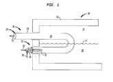
- FIG. 1 shows an elevation view of an oxy-fuel burner of the present embodiment
- FIG. 2 shows an elevation view of an oxy-fuel burner of another embodiment
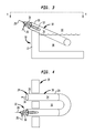
- FIG. 3 shows an elevation view of an oxy-fuel burner of still another embodiment
- FIG. 4 shows a plan view along line IV-IV of the embodiment of FIG. 3 ;
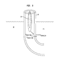
- FIG. 5 shows a cross-sectional view of a portion of the oxy-fuel burner of the present embodiments
- FIG. 6 shows a melter embodiment using a plurality of the oxy-fuel burners of for example FIG. 2 ;
- FIG. 7 shows an elevation view of an oxy-fuel burner of still another embodiment
- FIG. 8 shows a plan view along line VIII-VIII of the embodiment of FIG. 7 ;
- FIG. 9 shows an elevation view of an oxy-fuel burner of still another embodiment.
- the present embodiments provide for improved heat transfer with respect to the products to be melted.
- FIGS. 1-6 find use for example in reverberatory furnaces for aluminum and/or copper melting.
- the burner embodiments are disposed such that a substantial portion of such embodiments are submerged in the molten or semi-molten metal, while products of combustion of the burner embodiments are exhausted so as not to contact the melt.
- a melting furnace shown generally at 10 includes a side wall 12 constructed to provide a combustion chamber 14 therein in which a material to be melted is disposed which will be brought to a molten consistency as shown generally at 16 as a molten or semi-molten bath or melt.
- the oxy-fuel burner or burner 18 is constructed in a tubular shape having for example a circular cross section, with an inlet shown generally at 22 and an outlet or exhaust shown generally at 24.
- An oxygen feed 26 and a fuel feed 28 are connected to a burner portion 30 for providing a combustion flame 32 at an interior 34 of the burner tube 18.
- the interior 34 of the burner tube 18 is hollow, wherein the combustion flame 32 provides for the necessary heat to be transferred through the burner tube 18 to contact and heat the molten bath 16. That portion of the interior 34 exposed only to the combustion atmosphere 14, and not the melt 16, provides for heating of the combustion atmosphere 14 to further maintain the molten consistency of the bath 16 after such material has been melted.
- Exhaust gases from the combustion flame 32 are exhausted through the outlet 24 as indicated by arrow 36.
- the exhaust 36 may be sent to a scrubber or other capture device (neither of which is shown).
- a material from which the tube 18 is constructed is selected from silicon carbide or a material with similar characteristics, i.e. such material being able to withstand the characteristics of the combustion atmosphere 14 and the bath 16.
- the inlet 22 and the outlet 24 may be arranged so that they are parallel and in a common plane.
- That portion of the burner tube 18 in direct contact with the melt 16 provides the heat transfer effect for melting and maintaining the molten aspect of the bath 16.
- Approximately 20% to 80% of the tube 18 may be submerged in the bath 16.
- the burner 18 may be arranged in the furnace 10 up to 90° from the vertical or in other words up to 90% from a surface of the melt 16. Such a range of disposition is shown for example when comparing FIG. 2 and FIG. 3 .
- Heating of the tube interior by all the embodiments of FIGS. 1-6 is by convection and radiation.
- the quotient (Q) of radiation and the quotient of convection is added to the quotient of conduction to facilitate the melting which occurs in, for example, an aluminum (Al) bath 16.
- the oxy-fuel flame that is created at an interior of the burner tube 18 transfers energy to the tube by convection and radiation.
- the heated exhaust gases from the flame made up of carbon dioxide and water vapor, circulate inside the tube and in turn transfer energy to the tube's inside surface.
- Radiation in this case, the relatively bright oxy-fuel flame created inside the tube, transfers energy in the form of heat via wavelengths of light.
- the burners of for example those shown in FIGS. 1 or 2 are mounted in a furnace for operation.
- the furnace 10 includes the side wall 12 constructed to provide the combustion chamber 14 in which is charged a metal or alloy material to be melted into a bath 16.
- the burners 18 will be employed to provide the melting of the metallic charge material.
- the portion of the tube 18 shown generally at 38 lies below the surface of the molten or semi-molten bath 16.
- the side wall 12 is constructed with a top 40 and a bottom 42.
- the top 40 and the bottom 42 are joined together with stepped side walls 44, 46.
- the burners 18 selected for use in the embodiment of FIG. 6 have the inlet portion 22 disposed at the corresponding stepped side walls 44,46, while the outlet portion 24 containing for the exhaust 36 is provided for at the top 40.
- the exhaust 36 may be released to a scrubber or other capture device (not shown) away and elevated from the inlet 22 of the tubular burner 18. Neither exhaust gases nor particulate matter are introduced into the chamber 14 or the bath 16.
- the heat transfer via an oxy-fuel burner in a radiant tube submerged into the metal to be melted, is more efficient than the conventional method wherein a direct fired air-fuel burner is positioned in a furnace such that the flame is developed above the metal to be heated.
- the improved heat transfer provided by the burner embodiments results in more efficient and economic fuel consumption.
- the products of combustion at the interior 34 of the tubular burner 18 do not contact the molten metal in the bath 16, thereby reducing if not eliminating oxidation of the composition being melted in the bath 16.
- combustion occurs in the tube, and not in the chamber 14 (head space) above the bath 16, this translates into being able to use a smaller melter or furnace 10, thereby reducing the initial capital expense and ongoing operating expense.
- the combustion chamber 14 or head space can be at a reduced or minimum height which correspondingly translates into reduced air infiltration to the furnace and reduced oxidation of, for example, aluminum if such metal is being processed in the furnace.
- an inert gas can be provided through injection port 52 into the chamber 14 above the molten metal (the gas being confined to the chamber 14 by the walls of the furnace), as shown by arrows 54, to protect the material from oxidation caused by ambient air possibly leaking into the furnace through a furnace door 50 or other openings in the furnace structure.
- the inerting gas 54 can be selected from nitrogen, argon or similar inert gas.
- the door 50 can include a transparent portion of heat resistant glass for observing the combustion chamber, material being melted, and the furnace operation. Injecting the inert gas into the chamber 14 would not be practical or effective in a conventional furnace because the injected nitrogen would mix with the products of combustion from the flame, i.e., CO 2 , H 2 O and N 2 in some cases.
- the tubular burner 18 is constructed in an "L" shape.
- the embodiment of FIG. 9 shows the tubular burner 18 constructed in a "W" shape.
- a portion of a respective one of the tubular burners 18 is disposed to contact the particulate material to be melted, or submerged in the bath 16 for heating thereof, as may be done with other of the embodiments herein.
- the tubular member 18 can be formed in a myriad of different shapes, a portion of which is submerged into the bath 16.
- FIGS. 7-9 can be arranged individually or in combination with each other in a furnace 10 as shown in FIG. 6 .
- the burner 18 is fabricated from material that can withstand thermal and mechanical shock, chemical reaction (fluxing) and be able to absorb and transfer heat readily and efficiently.
- the material from which a sidewall of the burner 18 is fabricated will not deform or be structurally compromised when in contact with the molten material in the bath 16.
- a method is also provided from the embodiments of FIGS. 1-9 for melting particulate material in a furnace, the method including providing a combustion flame in a hollow elongated member, heating the elongated member with the combustion flame, disposing at least a portion of the elongated member in the particulate material, and heating the particulate material by conduction of the heat from the elongated member for melting said particulate material.
- Reduced specific energy consumption will also be realized by the embodiments of FIGS. 1-9 , in view of the reduction of energy consumed per unit weight of metal, such as aluminum, melted. Reduced melting times result in increased productivity and lower production costs.
- the present embodiments can be used with copper, tin and magnesium furnaces or melters.
Landscapes
- Engineering & Computer Science (AREA)
- Chemical & Material Sciences (AREA)
- Combustion & Propulsion (AREA)
- Mechanical Engineering (AREA)
- General Engineering & Computer Science (AREA)
- Vertical, Hearth, Or Arc Furnaces (AREA)
- Furnace Details (AREA)
- Manufacture And Refinement Of Metals (AREA)
Applications Claiming Priority (1)
| Application Number | Priority Date | Filing Date | Title |
|---|---|---|---|
| US12/581,196 US20110088602A1 (en) | 2009-10-19 | 2009-10-19 | Submerged oxy-fuel burner |
Publications (1)
| Publication Number | Publication Date |
|---|---|
| EP2312209A2 true EP2312209A2 (fr) | 2011-04-20 |
Family
ID=43531021
Family Applications (1)
| Application Number | Title | Priority Date | Filing Date |
|---|---|---|---|
| EP10011182A Withdrawn EP2312209A2 (fr) | 2009-10-19 | 2010-09-28 | Brûleur d'oxycarburants submergé |
Country Status (3)
| Country | Link |
|---|---|
| US (1) | US20110088602A1 (fr) |
| EP (1) | EP2312209A2 (fr) |
| BR (1) | BRPI1004239A2 (fr) |
Cited By (1)
| Publication number | Priority date | Publication date | Assignee | Title |
|---|---|---|---|---|
| IT201700047214A1 (it) * | 2017-05-02 | 2018-11-02 | Botta Forni Ind S R L | Forno di mantenimento |
Family Cites Families (6)
| Publication number | Priority date | Publication date | Assignee | Title |
|---|---|---|---|---|
| US4203761A (en) * | 1973-02-21 | 1980-05-20 | Robert C. LeMay | Process of smelting with submerged burner |
| US4308855A (en) * | 1976-11-03 | 1982-01-05 | Schallert Joseph M | Submerged burner furnace |
| US4570612A (en) * | 1984-11-19 | 1986-02-18 | Carrier Corporation | Induced draft submerged burner |
| US6109062A (en) * | 1996-10-08 | 2000-08-29 | Richards; Raymond S. | Apparatus for melting molten material |
| FR2774085B3 (fr) * | 1998-01-26 | 2000-02-25 | Saint Gobain Vitrage | Procede de fusion et d'affinage de matieres vitrifiables |
| FR2832704B1 (fr) * | 2001-11-27 | 2004-02-20 | Saint Gobain Isover | Dispositif et procede de fusion de matieres vitrifiables |
-
2009
- 2009-10-19 US US12/581,196 patent/US20110088602A1/en not_active Abandoned
-
2010
- 2010-09-28 EP EP10011182A patent/EP2312209A2/fr not_active Withdrawn
- 2010-10-19 BR BRPI1004239-3A patent/BRPI1004239A2/pt not_active Application Discontinuation
Non-Patent Citations (1)
| Title |
|---|
| None |
Cited By (1)
| Publication number | Priority date | Publication date | Assignee | Title |
|---|---|---|---|---|
| IT201700047214A1 (it) * | 2017-05-02 | 2018-11-02 | Botta Forni Ind S R L | Forno di mantenimento |
Also Published As
| Publication number | Publication date |
|---|---|
| BRPI1004239A2 (pt) | 2013-02-19 |
| US20110088602A1 (en) | 2011-04-21 |
Similar Documents
| Publication | Publication Date | Title |
|---|---|---|
| CN1091870C (zh) | 无氧化加热方法及装置 | |
| US5563903A (en) | Aluminum melting with reduced dross formation | |
| CA2776730C (fr) | Procede de chauffage et systeme de controle d'entree d'air dans les espaces clos | |
| EP2312209A2 (fr) | Brûleur d'oxycarburants submergé | |
| JP6654502B2 (ja) | ガラス溶融装置 | |
| CN202824914U (zh) | 一种钎焊炉 | |
| NO841355L (no) | Fremgangsmaate ved drift av et matallurgisk anlegg | |
| LU93217B1 (fr) | Brûleur pour four à combustion submergée | |
| KR19990077486A (ko) | 로장입물에열을제공하기위한방법 | |
| CN102994779B (zh) | 隧道式双循环真空冶炼炉及其方法 | |
| CN102837095B (zh) | 一种钎焊炉 | |
| KR20180055821A (ko) | 노 | |
| CN105940123B (zh) | 不锈钢铸件固溶化以及表面光亮热处理方法与装置 | |
| CN209214316U (zh) | 一种钢板构建集中用煤气加热反射炉 | |
| RU164626U1 (ru) | Дуговая сталеплавильная печь | |
| TWI881534B (zh) | 鐵水的製造方法 | |
| JP2005069581A (ja) | アルミニウム溶解炉 | |
| US6053728A (en) | Furnace | |
| RU2009420C1 (ru) | Устройство для расплавления металлов и фурма | |
| JP2002088457A (ja) | 溶融亜鉛めっき装置 | |
| RU2007126474A (ru) | Печная установка и способ расплавления металлического или металлосодержащего сырья | |
| JPS62275030A (ja) | ガラス溶解炉 | |
| CN103673583A (zh) | 快速节能连铸熔铝炉主炉结构 | |
| RU2407805C2 (ru) | Способ выплавки стали в дуговой сталеплавильной печи и устройство для его осуществления | |
| CN207570302U (zh) | 液态介质电阻熔铝炉 |
Legal Events
| Date | Code | Title | Description |
|---|---|---|---|
| PUAI | Public reference made under article 153(3) epc to a published international application that has entered the european phase |
Free format text: ORIGINAL CODE: 0009012 |
|
| AK | Designated contracting states |
Kind code of ref document: A2 Designated state(s): AL AT BE BG CH CY CZ DE DK EE ES FI FR GB GR HR HU IE IS IT LI LT LU LV MC MK MT NL NO PL PT RO SE SI SK SM TR |
|
| AX | Request for extension of the european patent |
Extension state: BA ME RS |
|
| STAA | Information on the status of an ep patent application or granted ep patent |
Free format text: STATUS: THE APPLICATION IS DEEMED TO BE WITHDRAWN |
|
| 18D | Application deemed to be withdrawn |
Effective date: 20130403 |