EP2312212A2 - Poste de cuisson au gaz doté d'un brûleur à deux circuits - Google Patents
Poste de cuisson au gaz doté d'un brûleur à deux circuits Download PDFInfo
- Publication number
- EP2312212A2 EP2312212A2 EP10186943A EP10186943A EP2312212A2 EP 2312212 A2 EP2312212 A2 EP 2312212A2 EP 10186943 A EP10186943 A EP 10186943A EP 10186943 A EP10186943 A EP 10186943A EP 2312212 A2 EP2312212 A2 EP 2312212A2
- Authority
- EP
- European Patent Office
- Prior art keywords
- burner
- gas
- power
- gas flow
- power range
- Prior art date
- Legal status (The legal status is an assumption and is not a legal conclusion. Google has not performed a legal analysis and makes no representation as to the accuracy of the status listed.)
- Granted
Links
Images


Classifications
-
- F—MECHANICAL ENGINEERING; LIGHTING; HEATING; WEAPONS; BLASTING
- F23—COMBUSTION APPARATUS; COMBUSTION PROCESSES
- F23D—BURNERS
- F23D14/00—Burners for combustion of a gas, e.g. of a gas stored under pressure as a liquid
- F23D14/02—Premix gas burners, i.e. in which gaseous fuel is mixed with combustion air upstream of the combustion zone
- F23D14/04—Premix gas burners, i.e. in which gaseous fuel is mixed with combustion air upstream of the combustion zone induction type, e.g. Bunsen burner
- F23D14/06—Premix gas burners, i.e. in which gaseous fuel is mixed with combustion air upstream of the combustion zone induction type, e.g. Bunsen burner with radial outlets at the burner head
-
- F—MECHANICAL ENGINEERING; LIGHTING; HEATING; WEAPONS; BLASTING
- F23—COMBUSTION APPARATUS; COMBUSTION PROCESSES
- F23N—REGULATING OR CONTROLLING COMBUSTION
- F23N1/00—Regulating fuel supply
- F23N1/005—Regulating fuel supply using electrical or electromechanical means
-
- F—MECHANICAL ENGINEERING; LIGHTING; HEATING; WEAPONS; BLASTING
- F23—COMBUSTION APPARATUS; COMBUSTION PROCESSES
- F23D—BURNERS
- F23D2900/00—Special features of, or arrangements for burners using fluid fuels or solid fuels suspended in a carrier gas
- F23D2900/14—Special features of gas burners
- F23D2900/14062—Special features of gas burners for cooking ranges having multiple flame rings
-
- F—MECHANICAL ENGINEERING; LIGHTING; HEATING; WEAPONS; BLASTING
- F23—COMBUSTION APPARATUS; COMBUSTION PROCESSES
- F23N—REGULATING OR CONTROLLING COMBUSTION
- F23N2235/00—Valves, nozzles or pumps
- F23N2235/12—Fuel valves
- F23N2235/14—Fuel valves electromagnetically operated
Definitions
- the invention relates to a gas hob with a gas burner, which comprises an internal burner and at least one external burner, and a gas supply unit according to the preamble of one of the independent claims 1 or 6.
- the gas burner of the generic gas hob has an internal burner and an external burner, which are supplied separately from each other with gas. Such gas burners are also referred to as two-circuit burners.
- a gas supply unit which usually comprises a mechanically or electrically actuable gas valve, controls the gas flow to the internal burner and the external burner of the gas burner in dependence on the specification by an operator by means of a suitable operating element.
- a control element is, for example, a mechanically operable rotary knob, but also an electronic user interface, such as a plus / minus button or a touch slider into consideration.
- a first power range is defined with low burner power, in which only the gas flow to the internal burner is open.
- the gas flow to the internal burner can be varied between a minimum value and a maximum value.
- the gas flow is opened to the outer burner.
- burner power adjustment is usually accomplished by varying the gas flow to the outside burner between a minimum and a maximum value.
- the gas flow to the internal burner is set to the maximum value.
- the present invention has for its object to provide a generic gas hob available, which has a continuous performance as possible.
- a first solution of this object according to the invention provides that the gas supply unit is designed such that in the second power range of the gas burner for adjusting the burner output, the gas flow to the internal burner is additionally varied between a minimum value and a maximum value. This adjusts the burner output in the second power range both via the internal burner and via the external burner. This enables a particularly differentiated setting of the burner output, in particular with a small burner output within the second power range.
- the gas flow to the inner burner is smaller than at the largest burner output within the first power range.
- the gas flow to the internal burner may be set to a minimum value.
- the total power of the gas burner is only slightly higher than the maximum burner power within the first power range, if the gas flow to the internal burner is at a maximum and the gas flow to the outside burner is interrupted.
- the gas flow to the internal burner is set to the maximum value.
- the adjustability of the gas flow to the internal burner is only within the second power range used to minimize the smallest burner power within the second power range.
- the gas supply unit may be designed such that, at least at a certain burner power within the second power range of the gas burner, in particular at the smallest burner power within the second power range, the gas flow to the outer burner is timed. By cycling the gas flow, the average power of the gas burner averaged over time can be further reduced. This can be used within the second power range of the gas burner to set the minimum power to a particularly small value.
- the clock ratio between the switch-on time and the switch-off time of the gas flow to the external burner is variable.
- the object mentioned at the outset is likewise achieved in that the gas supply unit is designed such that the gas flow to the outer burner is timed at least at the smallest burner output within the second power range of the gas burner.
- the average power of the gas burner, averaged over time can be set to particularly low values by cycling the outer burner.
- the internal burner burns continuously and can be set to a constant power value.
- the gas flow to the outer burner is continuously opened.
- a clocking of the outer burner is thus only at low burner power within the second power range.
- the open gas flow to the outer burner is set to the minimum value.
- the lowest power level within the second power range of the gas burner provides that the gas flow is clocked to the outer burner and also on the Minimum value is set.
- the next power stage provides that the outer burner burns continuously with a minimum value of the gas flow.
- the gas flow to the outer burner can be increased stepwise up to a maximum value.
- the gas flow to the internal burner is continuously opened.
- the flames on the inner burner can then be used, for example, to ignite the outer burner when it is operated in clock mode.
- the opened gas flow to the internal burner is set to a constant value, preferably to a maximum value.
- the power control in the second power range then takes place completely by means of the outer burner.
- the duty cycle between on-time and off-time of the outer burner is variable.
- the burner averaged over time can be adjusted in this way.
- the opened gas flow is varied to the internal burner between a minimum value and a maximum value.
- the power setting thus takes place by adjusting the flame size on the internal burner.
- the gas supply unit may be designed such that a low-power region of the gas burner is provided, in which the gas flow to the internal burner is timed and the gas flow to the external burner is interrupted. It is possible to perform the first power range of the gas burner as a low power range. The power setting then takes place in the first power range exclusively by changing the clock ratio between the on-time and off time of the gas burner, while the flame size is set to a constant value during the switch-on.
- the Low-power range can also be provided in addition to the first power range of the gas burner. In this case, in the first power range, the burner output is adjusted by varying the gas flow to the constantly burning internal burner. Even lower performance of the gas burner are achieved in the low power range by the inner burner is clocked at the lowest flame.
- the duty cycle between on time and off time of the indoor burner is variable.
- the gas flow to the internal burner is set to the minimum value.
- FIG. 1 is shown as a two-circuit burner gas burner 1 is shown.
- the gas burner 1 comprises an outer burner 2 with gas outlet openings 3 and an inner burner 4 with gas outlet openings 5.
- the outer burner 2 and the inner burner 4 can be supplied with gas independently of each other.
- a gas supply unit 14 provided for this purpose is in FIG. 2 shown.
- the gas supply unit 14 comprises a main gas line 6, in which a main gas valve 7 is arranged. From the main gas line 6 branches off behind the main gas valve 7, a branch line 8 to the outer burner 2 and a branch line 9 to the inner burner 4 from.
- a branch line 8 In each of the branch lines 8, 9 is an open-close valve 10, which may be embodied for example as a solenoid valve, and a control valve 11.
- the opening cross section of the respective branch line 8, 9 and thus the size of the gas flow to External burner 2 or the internal burner 4 are continuously or multi-stage set.
- the control valves 11 can be driven, for example, by means of a respective stepping motor.
- FIG. 3 the performance curve of a gas burner 1 in a gas hob of the prior art is shown.
- Plotted on the right-hand side of the diagram are the power levels that can be selected by an operator at an appropriate user interface.
- a user interface for example, a latched rotary knob, plus / minus buttons or a slider into consideration.
- the power output of the gas burner 1 is plotted on the vertical axis of the diagram.
- the power curve comprises three areas, a low power area 20, a first power region 21 and a second power region 22.
- the adjustment range of the gas burner 1 begins with the low-power region 20, in which the gas flow to the inner burner 4 is timed and the gas flow to the outer burner 2 is interrupted.
- the different power levels within the low power range 20 are achieved by varying the duty cycle between on time and off time of the indoor burner 4.
- the gas flow to the internal burner 4 is set to a minimum value.
- the minimum value of the gas flow is such that the flames on the internal burner 4 are as small as possible without extinguishing by themselves.
- the gas flow to the inner burner 4 is continuously opened, while the gas flow to the outer burner 2 is still closed.
- the different power levels within the first power range 21 are achieved by gradually increasing the gas flow to the internal burner 4 from the minimum value to a maximum value.
- the outer burner 2 is switched on.
- the different power levels within the second power range 22 are achieved by varying the gas flow to the outer burner 2 between a minimum value and a maximum value.
- the flames on the outer burner 2 continuously and the gas flow to the inner burner 4 is set constant to the maximum value.
- a disadvantage of this performance characteristic of a gas hob of the prior art is that in the region 15 of the transition from the first power region 21 to the second power region 22, a jump in performance arises that may be surprising for the operator of the gas hob. In addition, there is no possibility in region 15 of setting the power output of the gas burner 1 to an intermediate value.
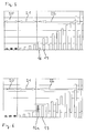
- FIG. 4 shows the performance curve of the gas burner 1 of a gas hob according to the invention, in which in the region of the transition between the first power region 21 and the second power region 22, the power curve is continuous and beyond, in comparison to the curve according to FIG. 3 , in this area an intermediate level exists.
- the power levels of the gas burner 1 are illustrated by a bar chart. Analogous to the FIGS. 3 and 4 On the right axis, the power levels selectable by the operator with the user interface are plotted, and the power output of the gas burner 1 is plotted on the vertical axis.
- the beams are divided into a lower portion and an upper portion.
- the lower portion of each bar represents the power output of the internal burner 4, the upper portion of the beam, the output of the external burner 2.
- a longitudinally dashed bar means that the relevant gas burner 1 is operated in a time-clocked mode.
- the height of the bar here reflects the power output of the gas burner 1 during its switch-on time.
- the average power of the gas burner 1, averaged over time is indicated by a horizontal bar in the area of the relevant bar.
- FIG. 5 describes a first preferred embodiment of the invention with reference to the power levels of the gas burner 1.
- the low-power region 20 of the inner burner 4 is operated in timed-clock mode.
- the gas flow to the continuously burning internal burner 4 is gradually increased.
- the second power range 22 of the outer burner 2 is switched on and the gas flow to the outer burner 2 increases gradually.
- the gas flow to the internal burner 4 is set to a smaller value than in the remaining stages of the second power range 22.
- the gas flow to the internal burner 4 in the stage 16 is set to a minimum value.
- the Gas flow to the outer burner 2 is also set to a minimum value in the stage 16. In this way, in the stage 16, a total output of the gas burner 1 is achieved, which is greater than the maximum power within the first power range 21 and less than the total power of the gas burner 1 in the power stage 17, in which the gas flow to the internal burner 4 to a Maximum value is set and the gas flow to the outer burner 2 to a minimum value.
- FIG. 6 illustrates the second embodiment of the invention, in which in the power stage 16 a comparable overall performance of the gas burner 1 is achieved as in the embodiment according to FIG. 5 in the power stage 16.
- the gas flow to the internal burner 4 is set to a maximum value.
- the gas flow to the outer burner 2 is set to a minimum value and moreover clocked in time.
- the cycle ratio between the on-time and the off-time of the outer burner is such that the total output of the gas burner 1 in the power stage 16a is between the highest power in the first power range 21 and the total power of the gas burner 1 in the next higher power level 17.
- a continuous transition between the first power region 21 and the second power region 22 is ensured with regard to the power output of the gas burner 1.
- the power difference between the highest power in the first power range 21 and the lowest power in the second power range 22 substantially corresponds to the power difference between two levels within the second power range 22.
- An alternative variant of the invention provides to combine the two embodiments of the invention described above and thus to allow both a clocking of the gas flow to the outer burner 2 and a variation of the gas flow to the inner burner 4 in the second power range of the gas burner. It is possible either to clock either the gas flow to the outer burner 2 or to vary the gas flow to the inner burner 4. It is also possible to simultaneously clock the gas flow to the outer burner 2 and to vary the gas flow to the inner burner 4.
Landscapes
- Engineering & Computer Science (AREA)
- Chemical & Material Sciences (AREA)
- Combustion & Propulsion (AREA)
- Mechanical Engineering (AREA)
- General Engineering & Computer Science (AREA)
- Control Of Combustion (AREA)
- Feeding And Controlling Fuel (AREA)
- Regulation And Control Of Combustion (AREA)
Priority Applications (1)
| Application Number | Priority Date | Filing Date | Title |
|---|---|---|---|
| EP10186943.6A EP2312212B1 (fr) | 2009-10-14 | 2010-10-08 | Poste de cuisson au gaz doté d'un brûleur à deux circuits |
Applications Claiming Priority (2)
| Application Number | Priority Date | Filing Date | Title |
|---|---|---|---|
| EP09290791 | 2009-10-14 | ||
| EP10186943.6A EP2312212B1 (fr) | 2009-10-14 | 2010-10-08 | Poste de cuisson au gaz doté d'un brûleur à deux circuits |
Publications (3)
| Publication Number | Publication Date |
|---|---|
| EP2312212A2 true EP2312212A2 (fr) | 2011-04-20 |
| EP2312212A3 EP2312212A3 (fr) | 2018-01-03 |
| EP2312212B1 EP2312212B1 (fr) | 2019-12-11 |
Family
ID=43432058
Family Applications (1)
| Application Number | Title | Priority Date | Filing Date |
|---|---|---|---|
| EP10186943.6A Active EP2312212B1 (fr) | 2009-10-14 | 2010-10-08 | Poste de cuisson au gaz doté d'un brûleur à deux circuits |
Country Status (1)
| Country | Link |
|---|---|
| EP (1) | EP2312212B1 (fr) |
Cited By (10)
| Publication number | Priority date | Publication date | Assignee | Title |
|---|---|---|---|---|
| EP2348255A3 (fr) * | 2010-01-25 | 2012-07-18 | E.G.O. Elektro-Gerätebau GmbH | Système de brûleur à deux circuits et procédé de fonctionnement d'un tel système de brûleur à deux circuits |
| ITMI20111738A1 (it) * | 2011-09-27 | 2013-03-28 | Smeg Spa | Bruciatore per un piano di cottura a gas e piano di cottura a gas incorporante tale bruciatore |
| WO2011144491A3 (fr) * | 2010-05-20 | 2013-04-11 | BSH Bosch und Siemens Hausgeräte GmbH | Unité valve à gaz pour un brûleur à deux circuits |
| DE102012200342A1 (de) * | 2012-01-11 | 2013-07-11 | E.G.O. Elektro-Gerätebau GmbH | Verfahren zur Ansteuerung von mehreren Gasbrennern eines Gaskochgerätes |
| FR2988812A1 (fr) * | 2012-03-30 | 2013-10-04 | Sunaero Helitest | Dispositif et procede pour emettre un rayonnement infrarouge par combustion catalytique, et module de commande pour commander un tel dispositif suivant un tel procede |
| DE102012219039A1 (de) * | 2012-10-18 | 2014-04-24 | E.G.O. Elektro-Gerätebau GmbH | Verfahren zum Betrieb eines Gaskochgeräts und Gaskochgerät |
| WO2014082755A1 (fr) * | 2012-11-30 | 2014-06-05 | German Gabtec Gmbh | Commande de l'amenée de gaz d'un brûleur à gaz |
| EP2703723B1 (fr) | 2012-08-28 | 2016-10-12 | Electrolux Home Products Corporation N.V. | Procédé de fonctionnement d'un brûleur à gaz d'un appareil de cuisson |
| EP3376104A1 (fr) * | 2017-03-16 | 2018-09-19 | Vestel Elektronik Sanayi ve Ticaret A.S. | Brûleur à gaz réglable |
| WO2023072482A1 (fr) * | 2021-10-29 | 2023-05-04 | BSH Hausgeräte GmbH | Procédé de fonctionnement d'un brûleur à gaz à double circuit, unité de commande, brûleur à gaz à double circuit et cuisinière à gaz |
Family Cites Families (6)
| Publication number | Priority date | Publication date | Assignee | Title |
|---|---|---|---|---|
| CH194869A (de) * | 1937-02-19 | 1937-12-31 | Wa Gas Apparate A G Zuerich Fa | Gasbrenner. |
| US2781779A (en) * | 1952-01-26 | 1957-02-19 | W J Schoenberger Co | Gas range burner control |
| JPS5636929U (fr) * | 1979-08-27 | 1981-04-08 | ||
| DE19949600A1 (de) * | 1999-10-14 | 2001-04-19 | Bsh Bosch Siemens Hausgeraete | Gasbeheiztes Hausgerät |
| US6315552B1 (en) * | 2000-03-31 | 2001-11-13 | General Electric Company | Dual fuel circuit gas burner |
| ITVE20070031A1 (it) * | 2007-05-17 | 2008-11-18 | Defendi Italy Srl | Rubinetto gas con sicurezza per bruciatore dual. |
-
2010
- 2010-10-08 EP EP10186943.6A patent/EP2312212B1/fr active Active
Non-Patent Citations (1)
| Title |
|---|
| None |
Cited By (16)
| Publication number | Priority date | Publication date | Assignee | Title |
|---|---|---|---|---|
| EP2348255A3 (fr) * | 2010-01-25 | 2012-07-18 | E.G.O. Elektro-Gerätebau GmbH | Système de brûleur à deux circuits et procédé de fonctionnement d'un tel système de brûleur à deux circuits |
| US8960234B2 (en) | 2010-05-20 | 2015-02-24 | Bsh Bosch Und Siemens Hausgeraete Gmbh | Gas valve unit for a dual circuit burner |
| WO2011144491A3 (fr) * | 2010-05-20 | 2013-04-11 | BSH Bosch und Siemens Hausgeräte GmbH | Unité valve à gaz pour un brûleur à deux circuits |
| EA022688B1 (ru) * | 2010-05-20 | 2016-02-29 | Бсх Хаусгерете Гмбх | Газовый клапан для двухконтурной горелки |
| ITMI20111738A1 (it) * | 2011-09-27 | 2013-03-28 | Smeg Spa | Bruciatore per un piano di cottura a gas e piano di cottura a gas incorporante tale bruciatore |
| WO2013104498A1 (fr) * | 2012-01-11 | 2013-07-18 | E.G.O. Elektro-Gerätebau GmbH | Procédé de commande de plusieurs foyers gaz d'un appareil de cuisson au gaz |
| DE102012200342A1 (de) * | 2012-01-11 | 2013-07-11 | E.G.O. Elektro-Gerätebau GmbH | Verfahren zur Ansteuerung von mehreren Gasbrennern eines Gaskochgerätes |
| DE102012200342B4 (de) * | 2012-01-11 | 2017-03-23 | E.G.O. Elektro-Gerätebau GmbH | Verfahren zur Ansteuerung mehrerer Gasbrenner eines Gaskochfeldes |
| FR2988812A1 (fr) * | 2012-03-30 | 2013-10-04 | Sunaero Helitest | Dispositif et procede pour emettre un rayonnement infrarouge par combustion catalytique, et module de commande pour commander un tel dispositif suivant un tel procede |
| EP2703723B1 (fr) | 2012-08-28 | 2016-10-12 | Electrolux Home Products Corporation N.V. | Procédé de fonctionnement d'un brûleur à gaz d'un appareil de cuisson |
| US10739010B2 (en) | 2012-08-28 | 2020-08-11 | Electrolux Home Products Corporation N.V. | Method of operating a gas burner of a cooking appliance |
| DE102012219039A1 (de) * | 2012-10-18 | 2014-04-24 | E.G.O. Elektro-Gerätebau GmbH | Verfahren zum Betrieb eines Gaskochgeräts und Gaskochgerät |
| EP2909535B1 (fr) * | 2012-10-18 | 2019-12-04 | E.G.O. ELEKTRO-GERÄTEBAU GmbH | Procédé de fonctionnement d'un appareil de cuisson gaz et cuisinière à gaz |
| WO2014082755A1 (fr) * | 2012-11-30 | 2014-06-05 | German Gabtec Gmbh | Commande de l'amenée de gaz d'un brûleur à gaz |
| EP3376104A1 (fr) * | 2017-03-16 | 2018-09-19 | Vestel Elektronik Sanayi ve Ticaret A.S. | Brûleur à gaz réglable |
| WO2023072482A1 (fr) * | 2021-10-29 | 2023-05-04 | BSH Hausgeräte GmbH | Procédé de fonctionnement d'un brûleur à gaz à double circuit, unité de commande, brûleur à gaz à double circuit et cuisinière à gaz |
Also Published As
| Publication number | Publication date |
|---|---|
| EP2312212A3 (fr) | 2018-01-03 |
| EP2312212B1 (fr) | 2019-12-11 |
Similar Documents
| Publication | Publication Date | Title |
|---|---|---|
| EP2312212B1 (fr) | Poste de cuisson au gaz doté d'un brûleur à deux circuits | |
| EP2572142B1 (fr) | Unité valve à gaz pour un brûleur à deux circuits | |
| EP0818655B1 (fr) | Procédé et dispositif de commande de la grandeur de la flamme des appareils de cuison à gaz | |
| EP2160541B1 (fr) | Système de commande pour une cuisinière à gaz | |
| EP2572143B1 (fr) | Ensemble valve à gaz pourvu de deux sorties de gaz | |
| EP2189719B1 (fr) | Procédé de réglage d'une puissance de chauffe dans un brûleur à plusieurs couronnes, notamment brûleur à deux couronnes, ainsi que dispositif d'exécution d'un tel procédé | |
| DE602005002768T2 (de) | Haushaltgaskochgerät | |
| EP2171325B1 (fr) | Dispositif de réglage | |
| EP2649354A2 (fr) | Unité vanne à gaz | |
| EP1908333B1 (fr) | Procede de commande d un dispositif chauffant d'un appareil electrique chauffant a plusieurs dispositifs chauffants | |
| DE3829677A1 (de) | Verfahren und anordnung zur regelung von pulssteuerbaren brennern in einer waermetechnischen anlage | |
| EP1671066B1 (fr) | Fourneau gaz | |
| EP2390571A2 (fr) | Procédé de commande d'un brûleur à gaz et plaque de cuisson à gaz dotée de plusieurs brûleurs à gaz | |
| EP2345849B1 (fr) | Procédé de fonctionnement d'un appareil de cuisson au gaz électronique | |
| EP0836054B1 (fr) | Procédé et dispositif de commande de la grandeur de la flamme des appareils de cuisson à gaz | |
| EP0859193A1 (fr) | Tableau d'affichage et de commande pour une cuisinière, en particulier pour un four ménager | |
| EP2652398B1 (fr) | Unité vanne à gaz pour un brûleur à deux circuits | |
| DE19752472A1 (de) | Anordnung und Verfahren zum Steuern einer Heizvorrichtung für Gaskochmulden | |
| EP2469172B1 (fr) | Poste de cuisson au gaz doté d'une commande automatique | |
| EP3149406A2 (fr) | Soupape de régulation de gaz, table de cuisson et cuisinière à gaz | |
| DE102007040698A1 (de) | Verfahren zur Steuerung eines Ventils für ein Fluidum und damit ausgestattetes Haushaltsgerät | |
| AT393583B (de) | Temperatursteuereinrichtung fuer einen backofen | |
| EP3146269B1 (fr) | Montage, plaque de cuisson et appareil de cuisson à gaz | |
| DE3544583A1 (de) | Drehschalter fuer gasherde | |
| EP1891376A2 (fr) | Robinet a gaz |
Legal Events
| Date | Code | Title | Description |
|---|---|---|---|
| PUAI | Public reference made under article 153(3) epc to a published international application that has entered the european phase |
Free format text: ORIGINAL CODE: 0009012 |
|
| AK | Designated contracting states |
Kind code of ref document: A2 Designated state(s): AL AT BE BG CH CY CZ DE DK EE ES FI FR GB GR HR HU IE IS IT LI LT LU LV MC MK MT NL NO PL PT RO RS SE SI SK SM TR |
|
| AX | Request for extension of the european patent |
Extension state: BA ME |
|
| RAP1 | Party data changed (applicant data changed or rights of an application transferred) |
Owner name: BSH HAUSGERAETE GMBH |
|
| PUAL | Search report despatched |
Free format text: ORIGINAL CODE: 0009013 |
|
| AK | Designated contracting states |
Kind code of ref document: A3 Designated state(s): AL AT BE BG CH CY CZ DE DK EE ES FI FR GB GR HR HU IE IS IT LI LT LU LV MC MK MT NL NO PL PT RO RS SE SI SK SM TR |
|
| AX | Request for extension of the european patent |
Extension state: BA ME |
|
| RIC1 | Information provided on ipc code assigned before grant |
Ipc: F23N 1/00 20060101ALI20171128BHEP Ipc: F23D 14/06 20060101AFI20171128BHEP |
|
| STAA | Information on the status of an ep patent application or granted ep patent |
Free format text: STATUS: REQUEST FOR EXAMINATION WAS MADE |
|
| 17P | Request for examination filed |
Effective date: 20180703 |
|
| RBV | Designated contracting states (corrected) |
Designated state(s): AL AT BE BG CH CY CZ DE DK EE ES FI FR GB GR HR HU IE IS IT LI LT LU LV MC MK MT NL NO PL PT RO RS SE SI SK SM TR |
|
| STAA | Information on the status of an ep patent application or granted ep patent |
Free format text: STATUS: EXAMINATION IS IN PROGRESS |
|
| 17Q | First examination report despatched |
Effective date: 20181206 |
|
| GRAP | Despatch of communication of intention to grant a patent |
Free format text: ORIGINAL CODE: EPIDOSNIGR1 |
|
| STAA | Information on the status of an ep patent application or granted ep patent |
Free format text: STATUS: GRANT OF PATENT IS INTENDED |
|
| INTG | Intention to grant announced |
Effective date: 20190524 |
|
| GRAS | Grant fee paid |
Free format text: ORIGINAL CODE: EPIDOSNIGR3 |
|
| GRAA | (expected) grant |
Free format text: ORIGINAL CODE: 0009210 |
|
| STAA | Information on the status of an ep patent application or granted ep patent |
Free format text: STATUS: THE PATENT HAS BEEN GRANTED |
|
| AK | Designated contracting states |
Kind code of ref document: B1 Designated state(s): AL AT BE BG CH CY CZ DE DK EE ES FI FR GB GR HR HU IE IS IT LI LT LU LV MC MK MT NL NO PL PT RO RS SE SI SK SM TR |
|
| REG | Reference to a national code |
Ref country code: GB Ref legal event code: FG4D Free format text: NOT ENGLISH |
|
| REG | Reference to a national code |
Ref country code: CH Ref legal event code: EP |
|
| REG | Reference to a national code |
Ref country code: AT Ref legal event code: REF Ref document number: 1212563 Country of ref document: AT Kind code of ref document: T Effective date: 20191215 |
|
| REG | Reference to a national code |
Ref country code: DE Ref legal event code: R096 Ref document number: 502010016404 Country of ref document: DE |
|
| REG | Reference to a national code |
Ref country code: IE Ref legal event code: FG4D Free format text: LANGUAGE OF EP DOCUMENT: GERMAN |
|
| REG | Reference to a national code |
Ref country code: NL Ref legal event code: MP Effective date: 20191211 |
|
| REG | Reference to a national code |
Ref country code: LT Ref legal event code: MG4D |
|
| PG25 | Lapsed in a contracting state [announced via postgrant information from national office to epo] |
Ref country code: SE Free format text: LAPSE BECAUSE OF FAILURE TO SUBMIT A TRANSLATION OF THE DESCRIPTION OR TO PAY THE FEE WITHIN THE PRESCRIBED TIME-LIMIT Effective date: 20191211 Ref country code: LV Free format text: LAPSE BECAUSE OF FAILURE TO SUBMIT A TRANSLATION OF THE DESCRIPTION OR TO PAY THE FEE WITHIN THE PRESCRIBED TIME-LIMIT Effective date: 20191211 Ref country code: BG Free format text: LAPSE BECAUSE OF FAILURE TO SUBMIT A TRANSLATION OF THE DESCRIPTION OR TO PAY THE FEE WITHIN THE PRESCRIBED TIME-LIMIT Effective date: 20200311 Ref country code: FI Free format text: LAPSE BECAUSE OF FAILURE TO SUBMIT A TRANSLATION OF THE DESCRIPTION OR TO PAY THE FEE WITHIN THE PRESCRIBED TIME-LIMIT Effective date: 20191211 Ref country code: NO Free format text: LAPSE BECAUSE OF FAILURE TO SUBMIT A TRANSLATION OF THE DESCRIPTION OR TO PAY THE FEE WITHIN THE PRESCRIBED TIME-LIMIT Effective date: 20200311 Ref country code: GR Free format text: LAPSE BECAUSE OF FAILURE TO SUBMIT A TRANSLATION OF THE DESCRIPTION OR TO PAY THE FEE WITHIN THE PRESCRIBED TIME-LIMIT Effective date: 20200312 Ref country code: LT Free format text: LAPSE BECAUSE OF FAILURE TO SUBMIT A TRANSLATION OF THE DESCRIPTION OR TO PAY THE FEE WITHIN THE PRESCRIBED TIME-LIMIT Effective date: 20191211 Ref country code: ES Free format text: LAPSE BECAUSE OF FAILURE TO SUBMIT A TRANSLATION OF THE DESCRIPTION OR TO PAY THE FEE WITHIN THE PRESCRIBED TIME-LIMIT Effective date: 20191211 |
|
| PG25 | Lapsed in a contracting state [announced via postgrant information from national office to epo] |
Ref country code: RS Free format text: LAPSE BECAUSE OF FAILURE TO SUBMIT A TRANSLATION OF THE DESCRIPTION OR TO PAY THE FEE WITHIN THE PRESCRIBED TIME-LIMIT Effective date: 20191211 Ref country code: HR Free format text: LAPSE BECAUSE OF FAILURE TO SUBMIT A TRANSLATION OF THE DESCRIPTION OR TO PAY THE FEE WITHIN THE PRESCRIBED TIME-LIMIT Effective date: 20191211 |
|
| PG25 | Lapsed in a contracting state [announced via postgrant information from national office to epo] |
Ref country code: AL Free format text: LAPSE BECAUSE OF FAILURE TO SUBMIT A TRANSLATION OF THE DESCRIPTION OR TO PAY THE FEE WITHIN THE PRESCRIBED TIME-LIMIT Effective date: 20191211 |
|
| PG25 | Lapsed in a contracting state [announced via postgrant information from national office to epo] |
Ref country code: RO Free format text: LAPSE BECAUSE OF FAILURE TO SUBMIT A TRANSLATION OF THE DESCRIPTION OR TO PAY THE FEE WITHIN THE PRESCRIBED TIME-LIMIT Effective date: 20191211 Ref country code: NL Free format text: LAPSE BECAUSE OF FAILURE TO SUBMIT A TRANSLATION OF THE DESCRIPTION OR TO PAY THE FEE WITHIN THE PRESCRIBED TIME-LIMIT Effective date: 20191211 Ref country code: CZ Free format text: LAPSE BECAUSE OF FAILURE TO SUBMIT A TRANSLATION OF THE DESCRIPTION OR TO PAY THE FEE WITHIN THE PRESCRIBED TIME-LIMIT Effective date: 20191211 Ref country code: EE Free format text: LAPSE BECAUSE OF FAILURE TO SUBMIT A TRANSLATION OF THE DESCRIPTION OR TO PAY THE FEE WITHIN THE PRESCRIBED TIME-LIMIT Effective date: 20191211 Ref country code: PT Free format text: LAPSE BECAUSE OF FAILURE TO SUBMIT A TRANSLATION OF THE DESCRIPTION OR TO PAY THE FEE WITHIN THE PRESCRIBED TIME-LIMIT Effective date: 20200506 |
|
| PG25 | Lapsed in a contracting state [announced via postgrant information from national office to epo] |
Ref country code: IS Free format text: LAPSE BECAUSE OF FAILURE TO SUBMIT A TRANSLATION OF THE DESCRIPTION OR TO PAY THE FEE WITHIN THE PRESCRIBED TIME-LIMIT Effective date: 20200411 Ref country code: SK Free format text: LAPSE BECAUSE OF FAILURE TO SUBMIT A TRANSLATION OF THE DESCRIPTION OR TO PAY THE FEE WITHIN THE PRESCRIBED TIME-LIMIT Effective date: 20191211 Ref country code: SM Free format text: LAPSE BECAUSE OF FAILURE TO SUBMIT A TRANSLATION OF THE DESCRIPTION OR TO PAY THE FEE WITHIN THE PRESCRIBED TIME-LIMIT Effective date: 20191211 |
|
| REG | Reference to a national code |
Ref country code: DE Ref legal event code: R097 Ref document number: 502010016404 Country of ref document: DE |
|
| PLBE | No opposition filed within time limit |
Free format text: ORIGINAL CODE: 0009261 |
|
| STAA | Information on the status of an ep patent application or granted ep patent |
Free format text: STATUS: NO OPPOSITION FILED WITHIN TIME LIMIT |
|
| PG25 | Lapsed in a contracting state [announced via postgrant information from national office to epo] |
Ref country code: DK Free format text: LAPSE BECAUSE OF FAILURE TO SUBMIT A TRANSLATION OF THE DESCRIPTION OR TO PAY THE FEE WITHIN THE PRESCRIBED TIME-LIMIT Effective date: 20191211 |
|
| 26N | No opposition filed |
Effective date: 20200914 |
|
| PG25 | Lapsed in a contracting state [announced via postgrant information from national office to epo] |
Ref country code: SI Free format text: LAPSE BECAUSE OF FAILURE TO SUBMIT A TRANSLATION OF THE DESCRIPTION OR TO PAY THE FEE WITHIN THE PRESCRIBED TIME-LIMIT Effective date: 20191211 Ref country code: PL Free format text: LAPSE BECAUSE OF FAILURE TO SUBMIT A TRANSLATION OF THE DESCRIPTION OR TO PAY THE FEE WITHIN THE PRESCRIBED TIME-LIMIT Effective date: 20191211 |
|
| REG | Reference to a national code |
Ref country code: CH Ref legal event code: PL |
|
| GBPC | Gb: european patent ceased through non-payment of renewal fee |
Effective date: 20201008 |
|
| PG25 | Lapsed in a contracting state [announced via postgrant information from national office to epo] |
Ref country code: MC Free format text: LAPSE BECAUSE OF FAILURE TO SUBMIT A TRANSLATION OF THE DESCRIPTION OR TO PAY THE FEE WITHIN THE PRESCRIBED TIME-LIMIT Effective date: 20191211 Ref country code: LU Free format text: LAPSE BECAUSE OF NON-PAYMENT OF DUE FEES Effective date: 20201008 |
|
| REG | Reference to a national code |
Ref country code: BE Ref legal event code: MM Effective date: 20201031 |
|
| PG25 | Lapsed in a contracting state [announced via postgrant information from national office to epo] |
Ref country code: FR Free format text: LAPSE BECAUSE OF NON-PAYMENT OF DUE FEES Effective date: 20201031 |
|
| PG25 | Lapsed in a contracting state [announced via postgrant information from national office to epo] |
Ref country code: GB Free format text: LAPSE BECAUSE OF NON-PAYMENT OF DUE FEES Effective date: 20201008 Ref country code: LI Free format text: LAPSE BECAUSE OF NON-PAYMENT OF DUE FEES Effective date: 20201031 Ref country code: BE Free format text: LAPSE BECAUSE OF NON-PAYMENT OF DUE FEES Effective date: 20201031 Ref country code: CH Free format text: LAPSE BECAUSE OF NON-PAYMENT OF DUE FEES Effective date: 20201031 |
|
| PG25 | Lapsed in a contracting state [announced via postgrant information from national office to epo] |
Ref country code: IE Free format text: LAPSE BECAUSE OF NON-PAYMENT OF DUE FEES Effective date: 20201008 |
|
| REG | Reference to a national code |
Ref country code: AT Ref legal event code: MM01 Ref document number: 1212563 Country of ref document: AT Kind code of ref document: T Effective date: 20201008 |
|
| PG25 | Lapsed in a contracting state [announced via postgrant information from national office to epo] |
Ref country code: AT Free format text: LAPSE BECAUSE OF NON-PAYMENT OF DUE FEES Effective date: 20201008 |
|
| PG25 | Lapsed in a contracting state [announced via postgrant information from national office to epo] |
Ref country code: MT Free format text: LAPSE BECAUSE OF FAILURE TO SUBMIT A TRANSLATION OF THE DESCRIPTION OR TO PAY THE FEE WITHIN THE PRESCRIBED TIME-LIMIT Effective date: 20191211 Ref country code: CY Free format text: LAPSE BECAUSE OF FAILURE TO SUBMIT A TRANSLATION OF THE DESCRIPTION OR TO PAY THE FEE WITHIN THE PRESCRIBED TIME-LIMIT Effective date: 20191211 |
|
| PG25 | Lapsed in a contracting state [announced via postgrant information from national office to epo] |
Ref country code: MK Free format text: LAPSE BECAUSE OF FAILURE TO SUBMIT A TRANSLATION OF THE DESCRIPTION OR TO PAY THE FEE WITHIN THE PRESCRIBED TIME-LIMIT Effective date: 20191211 |
|
| PGFP | Annual fee paid to national office [announced via postgrant information from national office to epo] |
Ref country code: DE Payment date: 20221031 Year of fee payment: 13 |
|
| REG | Reference to a national code |
Ref country code: DE Ref legal event code: R084 Ref document number: 502010016404 Country of ref document: DE |
|
| PGFP | Annual fee paid to national office [announced via postgrant information from national office to epo] |
Ref country code: TR Payment date: 20230929 Year of fee payment: 14 |
|
| PGFP | Annual fee paid to national office [announced via postgrant information from national office to epo] |
Ref country code: IT Payment date: 20231031 Year of fee payment: 14 |
|
| REG | Reference to a national code |
Ref country code: DE Ref legal event code: R119 Ref document number: 502010016404 Country of ref document: DE |
|
| PG25 | Lapsed in a contracting state [announced via postgrant information from national office to epo] |
Ref country code: DE Free format text: LAPSE BECAUSE OF NON-PAYMENT OF DUE FEES Effective date: 20240501 |
|
| PG25 | Lapsed in a contracting state [announced via postgrant information from national office to epo] |
Ref country code: IT Free format text: LAPSE BECAUSE OF NON-PAYMENT OF DUE FEES Effective date: 20241008 |