EP2312237A1 - Sonde für Erdwärmegewinnungsanlage - Google Patents
Sonde für Erdwärmegewinnungsanlage Download PDFInfo
- Publication number
- EP2312237A1 EP2312237A1 EP10187457A EP10187457A EP2312237A1 EP 2312237 A1 EP2312237 A1 EP 2312237A1 EP 10187457 A EP10187457 A EP 10187457A EP 10187457 A EP10187457 A EP 10187457A EP 2312237 A1 EP2312237 A1 EP 2312237A1
- Authority
- EP
- European Patent Office
- Prior art keywords
- probe
- membrane
- ducts
- thickness
- tip
- Prior art date
- Legal status (The legal status is an assumption and is not a legal conclusion. Google has not performed a legal analysis and makes no representation as to the accuracy of the status listed.)
- Granted
Links
Images


Classifications
-
- F—MECHANICAL ENGINEERING; LIGHTING; HEATING; WEAPONS; BLASTING
- F16—ENGINEERING ELEMENTS AND UNITS; GENERAL MEASURES FOR PRODUCING AND MAINTAINING EFFECTIVE FUNCTIONING OF MACHINES OR INSTALLATIONS; THERMAL INSULATION IN GENERAL
- F16L—PIPES; JOINTS OR FITTINGS FOR PIPES; SUPPORTS FOR PIPES, CABLES OR PROTECTIVE TUBING; MEANS FOR THERMAL INSULATION IN GENERAL
- F16L11/00—Hoses, i.e. flexible pipes
- F16L11/22—Multi-channel hoses
-
- F—MECHANICAL ENGINEERING; LIGHTING; HEATING; WEAPONS; BLASTING
- F24—HEATING; RANGES; VENTILATING
- F24T—GEOTHERMAL COLLECTORS; GEOTHERMAL SYSTEMS
- F24T10/00—Geothermal collectors
- F24T10/10—Geothermal collectors with circulation of working fluids through underground channels, the working fluids not coming into direct contact with the ground
- F24T10/13—Geothermal collectors with circulation of working fluids through underground channels, the working fluids not coming into direct contact with the ground using tube assemblies suitable for insertion into boreholes in the ground, e.g. geothermal probes
- F24T10/15—Geothermal collectors with circulation of working fluids through underground channels, the working fluids not coming into direct contact with the ground using tube assemblies suitable for insertion into boreholes in the ground, e.g. geothermal probes using bent tubes; using tubes assembled with connectors or with return headers
-
- Y—GENERAL TAGGING OF NEW TECHNOLOGICAL DEVELOPMENTS; GENERAL TAGGING OF CROSS-SECTIONAL TECHNOLOGIES SPANNING OVER SEVERAL SECTIONS OF THE IPC; TECHNICAL SUBJECTS COVERED BY FORMER USPC CROSS-REFERENCE ART COLLECTIONS [XRACs] AND DIGESTS
- Y02—TECHNOLOGIES OR APPLICATIONS FOR MITIGATION OR ADAPTATION AGAINST CLIMATE CHANGE
- Y02E—REDUCTION OF GREENHOUSE GAS [GHG] EMISSIONS, RELATED TO ENERGY GENERATION, TRANSMISSION OR DISTRIBUTION
- Y02E10/00—Energy generation through renewable energy sources
- Y02E10/10—Geothermal energy
Definitions
- the invention relates to a fluid circulation probe for geothermal installations.
- geothermal installations have developed using a difference in temperature between the ambient air and the ground to produce heat or cooling in a building through heat exchange.
- the circuit comprises a plurality of probes each consisting of a pipe of considerable length, the probes traversing a substantially horizontal surface buried at a predetermined depth in the ground.
- a highly verticalized circuit in which holes are formed in the ground, for example by coring, to allow the deployment of the probes in pairs so as to form the forward path and the return path of the buried portion . After the deployment of the probes, the hole is re-closed in the usual way and the vertical probes are connected to the rest of the circuit.
- the probes currently used may be of relatively long length so as to benefit from the highest temperature gradient possible.
- the tubes constituting the current probes are stored in the form of windings and are unrolled as they are deployed in the holes generally in sets of 2 or 4 rolls.
- the pipes must be deployed in pairs in the holes which implies simultaneity of unwinding. This requirement of synchronism is particularly difficult to obtain and one often finds descent offsets in the holes greatly complicating the installation phase.
- the diameter of the borehole is very important and therefore very expensive in time, labor and equipment, because it is impossible to properly lower the tubes and avoid for example the friction on the walls.
- the pallets containing the rolls are filmed with very strong heat-shrinkable plastics and a large workforce.
- the present invention overcomes all or part of the disadvantages of the techniques known hitherto and has for this purpose a fluid circulation probe for geothermal installation comprising two parallel ducts and an intermediate membrane joining the ducts.
- the membrane has a thickness less than that of the wall of the ducts and its junction areas with the ducts comprise connection fillet on each duct.
- the membrane is a continuous web of constant thickness between the two junction zones. So, no area of weakness mechanical is formed on the membrane, while preserving the possibility of a reduced thickness and good flexibility in winding.
- the present invention makes the choice of a reduced thickness to provide flexibility for the winding of the probe and its unfolding at the time of installation.
- the invention ensures a high mechanical strength of the assembly constituted by the connection fillet means avoiding any sudden dimensional variation within the assembly and consequently eliminating the stress concentrations at the junctions between the membrane. and the ducts.
- the probe according to the invention has a membrane width selected so as to limit the bulk but at the same time to limit the heat transfer between the two ducts.
- one of the ducts is generally the vector of a downward flow of cold fluid while the other conduit is the means of raising heated fluid.
- a dimensional ratio between the thickness of the membrane and the thickness of the wall of the ducts is selected so as to produce an assembly whose deformation capacities, in particular in winding and unwinding, are optimal.
- the probe comprises a nozzle whose configuration makes it possible to connect the ends of the conduits and, in an advantageous arrangement, which allows ballasting so as to facilitate the implantation of the probe in a hole.
- the present invention relates to a fluid circulation probe for geothermal installations, comprising two parallel conduits and an intermediate membrane joining the conduits, characterized in that the membrane has a thickness less than that of the duct walls and that its areas of junction with the ducts comprise connection fillet on each duct.
- the membrane is a continuous web along the probe and its thickness is preferably constant between the junction areas.
- the invention also relates to a geothermal installation incorporating at least one probe according to the invention as well as a method of manufacture and use of the probe.
- FIGS. 1 and 2 schematically a conventional installation method for geothermal energy using, for the figure 1 traditional tubes and, for the figure 2 , ducts formed in a probe according to the invention.
- the figure 1 does not reflect a complete geothermal circuit but illustrates the difficulties of setting up current pipes.
- the figure 2 shows on the contrary the interest of the invention.
- each tube 1 tends to take its own orientation and any disruption in the speed of unwinding generates problems of setting in place tubes 1 in the geothermal installation.
- a conventional solution used by geotechnicians is to deploy several pairs of tubes in a single hole. In this case, the The problem posed by the disruptions of deployment of the tubes 1 is even higher.
- the invention ensures the cohesion of the tubes during the storage and installation phases while preserving the sufficient flexibility of the assembly of the probe.
- the ducts 8, 9 are kept spaced but joined by means of a membrane 10 having substantially an elongate sheet shape in the longitudinal direction of the probe 7 and advantageously continuous made by extrusion.
- the width (or length of the spacing that it provides between the ducts 8, 9) of the membrane 10 is advantageously selected so as to ensure good thermal insulation between the two ducts 8, 9 but at the same time to limit the overall size and to adjust the bending deformation capacity of the membrane 10.
- the thickness 11 of the membrane 10 is less than the thickness of the wall 13 of the ducts 8, 9. This thickness is continuous so as to avoid areas of stress concentration or rigidity.
- the dimensional ranges of the various components of the probe as described above revealed, surprisingly, that the mechanical behavior of the probe was improved.
- the probe advantageously comprises connection fillets 12 at the junction between the membrane 10 and the conduits 8, 9.
- connection fillets 12 at the junction between the membrane 10 and the conduits 8, 9.
- four fillets are formed, two fillets 12 for connection with the conduit 8 and two fillets 12 for the connection with the duct 9.
- the fillets form roundings allowing a connection of decreasing thickness between each duct and the membrane, without abrupt variation of thickness.
- connection fillets 12 is identical and can be set at a value of 2 millimeters, which gives complete satisfaction, in particular for the tearing resistance between the membrane 10 and the conduits 8, 9. Without hindering the flexibility overall, such a connection fillet significantly strengthens the mechanical strength.
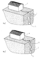
- a nozzle 14 In the lower part of the ducts, there is provided a nozzle 14 generally presented in figure 5 and detailed to Figures 9 to 11 .
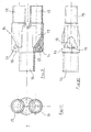
- the figure 9 shows in particular the formation of a tip 14 with a main body 17 comprising an interior volume causing the distal ends of the ducts 8, 9 to meet.
- a tip 14 For the connection between the ducts 8, 9 and the nozzle 14, portions of fitting 15 are provided.
- a base 16 is in continuity with the volume of the main body 17 as a siphon.
- the body 17 or any other part of the tip 14 comprises means for fixing a ballast.
- a ballast it is possible to report to the probe an element of sufficiently high weight to facilitate the introduction of the probe into the hole during installation.
- the fastening means comprise at least one attachment hole 19 and preferably two holes 19.
- the holes 19 are located on flanges 18 extending laterally towards the base 16 below the body 17. This configuration is not limiting.
- An extrusion machine is used for the linear production of the probe.
- the latter is advantageously made of high density polyethylene.
- the tip 14 is secured to the probe by a welding device moving at the same speed as the extrusion, so that the tip is attached to the probe without requiring a separate step and an additional manufacturing station.
- the set only has to be wrapped and circled without further manipulation.
Landscapes
- Engineering & Computer Science (AREA)
- General Engineering & Computer Science (AREA)
- Life Sciences & Earth Sciences (AREA)
- Mechanical Engineering (AREA)
- General Life Sciences & Earth Sciences (AREA)
- Sustainable Development (AREA)
- Sustainable Energy (AREA)
- Chemical & Material Sciences (AREA)
- Combustion & Propulsion (AREA)
- Investigating Or Analyzing Materials By The Use Of Magnetic Means (AREA)
- Rigid Pipes And Flexible Pipes (AREA)
Priority Applications (1)
| Application Number | Priority Date | Filing Date | Title |
|---|---|---|---|
| PL10187457T PL2312237T3 (pl) | 2009-10-16 | 2010-10-13 | Sonda geotermalna |
Applications Claiming Priority (1)
| Application Number | Priority Date | Filing Date | Title |
|---|---|---|---|
| FR0957256A FR2951530B1 (fr) | 2009-10-16 | 2009-10-16 | Sonde pour installations geothermiques |
Publications (2)
| Publication Number | Publication Date |
|---|---|
| EP2312237A1 true EP2312237A1 (de) | 2011-04-20 |
| EP2312237B1 EP2312237B1 (de) | 2014-05-07 |
Family
ID=42226144
Family Applications (1)
| Application Number | Title | Priority Date | Filing Date |
|---|---|---|---|
| EP10187457.6A Not-in-force EP2312237B1 (de) | 2009-10-16 | 2010-10-13 | Erdwärmesonde |
Country Status (4)
| Country | Link |
|---|---|
| EP (1) | EP2312237B1 (de) |
| ES (1) | ES2487535T3 (de) |
| FR (1) | FR2951530B1 (de) |
| PL (1) | PL2312237T3 (de) |
Cited By (5)
| Publication number | Priority date | Publication date | Assignee | Title |
|---|---|---|---|---|
| EP2738480A3 (de) * | 2012-11-29 | 2014-06-11 | Jansen AG | Sondenkörper |
| EP2738481A3 (de) * | 2012-11-29 | 2014-06-11 | Jansen AG | Sondenkörper |
| EP2840333A1 (de) * | 2013-08-22 | 2015-02-25 | MKM Mansfelder Kupfer und Messing GmbH | Verfahren zur Herstellung von U-förmigen Erdwärmesonden |
| EP3032188A1 (de) * | 2014-12-11 | 2016-06-15 | Jansen AG | Sondenkörper vorgesehen zum einbau in ein bohrloch als geothermiesonde |
| CN113531953A (zh) * | 2021-09-17 | 2021-10-22 | 同方德诚(山东)科技股份公司 | 一种多能源供冷供热的联动控制方法 |
Citations (8)
| Publication number | Priority date | Publication date | Assignee | Title |
|---|---|---|---|---|
| FR2562730A3 (fr) * | 1983-02-09 | 1985-10-11 | Wavin Bv | Garniture de canalisation pour cables |
| EP0231504A2 (de) * | 1986-02-07 | 1987-08-12 | Wavin B.V. | Einsatz für ein Kabelkanalrohr |
| DE4016726C1 (de) * | 1990-05-24 | 1991-07-25 | Dipl.-Ing. Dr. Ernst Vogelsang Gmbh & Co Kg, 4352 Herten, De | |
| EP0582118A1 (de) * | 1992-08-06 | 1994-02-09 | Sacac Hergiswil Ag | Erdsondengebilde, Distanzhalter für Erdsondengebilde, mindestens einteiliger Erdpfahl mit Erdsonde, Erdwärmegewinnungsanlage sowie deren Verfahren |
| DE20115397U1 (de) * | 2001-09-18 | 2001-12-13 | AETNA Energiesysteme GmbH, 15745 Wildau | Erdwärmesonde mit integriertem Abstandshalter |
| DE10243714B3 (de) * | 2002-09-20 | 2004-04-15 | Erbslöh Aluminium Gmbh | Hydraulikleitung und Verfahren zur Herstellung einer Hydraulikleitung sowie stranggepresstes Verbundprofil zur Verwendung in einem solchen Verfahren |
| US20050121169A1 (en) | 2003-12-09 | 2005-06-09 | Mcnair Edward F. | Geothermal heating and/or cooling apparatus and method of using same |
| US20050211437A1 (en) * | 2004-03-26 | 2005-09-29 | Mcnair Edward F | Geothermal pipe weight |
Family Cites Families (2)
| Publication number | Priority date | Publication date | Assignee | Title |
|---|---|---|---|---|
| FR2439078A1 (fr) * | 1978-10-16 | 1980-05-16 | Kuster Rene | Tubes, tuyaux et profiles creux en matiere plastique, procede et outil pour leur fabrication |
| DE8408571U1 (de) * | 1984-03-21 | 1984-06-28 | Festo KG, 7300 Esslingen | Pneumatikschlauch |
-
2009
- 2009-10-16 FR FR0957256A patent/FR2951530B1/fr not_active Expired - Fee Related
-
2010
- 2010-10-13 EP EP10187457.6A patent/EP2312237B1/de not_active Not-in-force
- 2010-10-13 ES ES10187457.6T patent/ES2487535T3/es active Active
- 2010-10-13 PL PL10187457T patent/PL2312237T3/pl unknown
Patent Citations (8)
| Publication number | Priority date | Publication date | Assignee | Title |
|---|---|---|---|---|
| FR2562730A3 (fr) * | 1983-02-09 | 1985-10-11 | Wavin Bv | Garniture de canalisation pour cables |
| EP0231504A2 (de) * | 1986-02-07 | 1987-08-12 | Wavin B.V. | Einsatz für ein Kabelkanalrohr |
| DE4016726C1 (de) * | 1990-05-24 | 1991-07-25 | Dipl.-Ing. Dr. Ernst Vogelsang Gmbh & Co Kg, 4352 Herten, De | |
| EP0582118A1 (de) * | 1992-08-06 | 1994-02-09 | Sacac Hergiswil Ag | Erdsondengebilde, Distanzhalter für Erdsondengebilde, mindestens einteiliger Erdpfahl mit Erdsonde, Erdwärmegewinnungsanlage sowie deren Verfahren |
| DE20115397U1 (de) * | 2001-09-18 | 2001-12-13 | AETNA Energiesysteme GmbH, 15745 Wildau | Erdwärmesonde mit integriertem Abstandshalter |
| DE10243714B3 (de) * | 2002-09-20 | 2004-04-15 | Erbslöh Aluminium Gmbh | Hydraulikleitung und Verfahren zur Herstellung einer Hydraulikleitung sowie stranggepresstes Verbundprofil zur Verwendung in einem solchen Verfahren |
| US20050121169A1 (en) | 2003-12-09 | 2005-06-09 | Mcnair Edward F. | Geothermal heating and/or cooling apparatus and method of using same |
| US20050211437A1 (en) * | 2004-03-26 | 2005-09-29 | Mcnair Edward F | Geothermal pipe weight |
Cited By (5)
| Publication number | Priority date | Publication date | Assignee | Title |
|---|---|---|---|---|
| EP2738480A3 (de) * | 2012-11-29 | 2014-06-11 | Jansen AG | Sondenkörper |
| EP2738481A3 (de) * | 2012-11-29 | 2014-06-11 | Jansen AG | Sondenkörper |
| EP2840333A1 (de) * | 2013-08-22 | 2015-02-25 | MKM Mansfelder Kupfer und Messing GmbH | Verfahren zur Herstellung von U-förmigen Erdwärmesonden |
| EP3032188A1 (de) * | 2014-12-11 | 2016-06-15 | Jansen AG | Sondenkörper vorgesehen zum einbau in ein bohrloch als geothermiesonde |
| CN113531953A (zh) * | 2021-09-17 | 2021-10-22 | 同方德诚(山东)科技股份公司 | 一种多能源供冷供热的联动控制方法 |
Also Published As
| Publication number | Publication date |
|---|---|
| FR2951530B1 (fr) | 2012-05-04 |
| ES2487535T3 (es) | 2014-08-21 |
| FR2951530A1 (fr) | 2011-04-22 |
| PL2312237T3 (pl) | 2014-12-31 |
| EP2312237B1 (de) | 2014-05-07 |
Similar Documents
| Publication | Publication Date | Title |
|---|---|---|
| EP2312237B1 (de) | Erdwärmesonde | |
| EP0483337B1 (de) | Rohrförmige flexible leitung mit integrierten heizvorrichtungen | |
| EP2558761B1 (de) | Leitung für den transport einer flüssigkeit mit einem kohlenwasserstoff und verfahren zur herstellung einer derartigen linie | |
| EP1340013B1 (de) | Flexible röhrenförmige leitung | |
| EP1987281B1 (de) | Element mit koaxialröhren einschliesslich eines innenrohres unter spannungsbelastung und herstellungsverfahren dafür | |
| FR2522457A1 (fr) | Element formant resistance bifilaire, element chauffant obtenu a partir de ce dernier et procede de fabrication d'un tel element chauffant | |
| FR2884905A1 (fr) | Sonde de captage de l'energie thermique du sol pour pompe a chaleur | |
| FR2507281A1 (fr) | Appareil et procede pour raccorder des elements tubulaires | |
| FR2958991A1 (fr) | Conduite pour le transport d'un fluide comprenant un hydrocarbure, et procede de fabrication d'une telle conduite. | |
| FR2648076A1 (fr) | Fil gaine profile destine notamment a former un insert d'electro-soudure | |
| FR2673264A1 (fr) | Conduite pour le transport de fluides, en particulier d'hydrocarbures. | |
| FR2580437A1 (fr) | Procede de fabrication d'un element tubulaire monobloc pour la protection de plusieurs cables et element fabrique selon ce procede | |
| EP3365591B1 (de) | Verfahren zur montage einer starren rohrleitung und zugehörige rohrleitung | |
| CH677250A5 (de) | ||
| FR2549301A1 (fr) | Procede pour realiser entre des tubes metalliques concentriques une jonction electriquement conductrice et susceptible de resister aux efforts | |
| FR2993637B1 (fr) | Ensemble de conduite de circulation de fluide pour structure d'echange thermique et procede de fabrication d'un tel ensemble | |
| EP3688243B1 (de) | Fertigbauelement, gebäude mit diesem bauelement und verfahren zur herstellung des zugehörigen bauelements | |
| FR2735511A1 (fr) | Gaine de cable a structure multi-couche, son procede de fabrication et machine pour mettre en oeuvre ce procede | |
| EP2706290A1 (de) | Träger, der elektrische Leiter umfasst, und Elektrifizierungssystem, bei dem solche Träger verwendet werden | |
| EP3080503A1 (de) | Verbundstreifen sowie verfahren zur herstellung einer verbindung zwischen zwei leitungen | |
| EP2652852B1 (de) | Leitungselement für elektrische kabel oder ähnichle kondukten, und das herstellungsverfahren desgleichen | |
| BE875898R (fr) | Joint pour tuyaux thermoplastiques a parois multiples et procede pour sa production | |
| WO2018115619A1 (fr) | Sonotrode à canaux de refroidissement non linéaires | |
| FR2598772A1 (fr) | Tube de canalisation isole thermiquement, a deux conducteurs sans disposition pour la dilatation, procede et dispositif de leur mise en oeuvre. | |
| WO2006079703A1 (fr) | Tige tubulaire de forage |
Legal Events
| Date | Code | Title | Description |
|---|---|---|---|
| PUAI | Public reference made under article 153(3) epc to a published international application that has entered the european phase |
Free format text: ORIGINAL CODE: 0009012 |
|
| AK | Designated contracting states |
Kind code of ref document: A1 Designated state(s): AL AT BE BG CH CY CZ DE DK EE ES FI FR GB GR HR HU IE IS IT LI LT LU LV MC MK MT NL NO PL PT RO RS SE SI SK SM TR |
|
| AX | Request for extension of the european patent |
Extension state: BA ME |
|
| 17P | Request for examination filed |
Effective date: 20111006 |
|
| GRAP | Despatch of communication of intention to grant a patent |
Free format text: ORIGINAL CODE: EPIDOSNIGR1 |
|
| INTG | Intention to grant announced |
Effective date: 20130814 |
|
| GRAP | Despatch of communication of intention to grant a patent |
Free format text: ORIGINAL CODE: EPIDOSNIGR1 |
|
| INTG | Intention to grant announced |
Effective date: 20140130 |
|
| GRAS | Grant fee paid |
Free format text: ORIGINAL CODE: EPIDOSNIGR3 |
|
| GRAA | (expected) grant |
Free format text: ORIGINAL CODE: 0009210 |
|
| AK | Designated contracting states |
Kind code of ref document: B1 Designated state(s): AL AT BE BG CH CY CZ DE DK EE ES FI FR GB GR HR HU IE IS IT LI LT LU LV MC MK MT NL NO PL PT RO RS SE SI SK SM TR |
|
| REG | Reference to a national code |
Ref country code: GB Ref legal event code: FG4D Free format text: NOT ENGLISH |
|
| REG | Reference to a national code |
Ref country code: AT Ref legal event code: REF Ref document number: 667001 Country of ref document: AT Kind code of ref document: T Effective date: 20140515 |
|
| REG | Reference to a national code |
Ref country code: IE Ref legal event code: FG4D Free format text: LANGUAGE OF EP DOCUMENT: FRENCH |
|
| REG | Reference to a national code |
Ref country code: DE Ref legal event code: R096 Ref document number: 602010015781 Country of ref document: DE Effective date: 20140626 |
|
| REG | Reference to a national code |
Ref country code: CH Ref legal event code: NV Representative=s name: P&TS SA, CH |
|
| REG | Reference to a national code |
Ref country code: ES Ref legal event code: FG2A Ref document number: 2487535 Country of ref document: ES Kind code of ref document: T3 Effective date: 20140821 |
|
| REG | Reference to a national code |
Ref country code: NL Ref legal event code: T3 |
|
| REG | Reference to a national code |
Ref country code: AT Ref legal event code: MK05 Ref document number: 667001 Country of ref document: AT Kind code of ref document: T Effective date: 20140507 |
|
| REG | Reference to a national code |
Ref country code: LT Ref legal event code: MG4D |
|
| PG25 | Lapsed in a contracting state [announced via postgrant information from national office to epo] |
Ref country code: NO Free format text: LAPSE BECAUSE OF FAILURE TO SUBMIT A TRANSLATION OF THE DESCRIPTION OR TO PAY THE FEE WITHIN THE PRESCRIBED TIME-LIMIT Effective date: 20140807 Ref country code: GR Free format text: LAPSE BECAUSE OF FAILURE TO SUBMIT A TRANSLATION OF THE DESCRIPTION OR TO PAY THE FEE WITHIN THE PRESCRIBED TIME-LIMIT Effective date: 20140808 Ref country code: FI Free format text: LAPSE BECAUSE OF FAILURE TO SUBMIT A TRANSLATION OF THE DESCRIPTION OR TO PAY THE FEE WITHIN THE PRESCRIBED TIME-LIMIT Effective date: 20140507 Ref country code: LT Free format text: LAPSE BECAUSE OF FAILURE TO SUBMIT A TRANSLATION OF THE DESCRIPTION OR TO PAY THE FEE WITHIN THE PRESCRIBED TIME-LIMIT Effective date: 20140507 Ref country code: CY Free format text: LAPSE BECAUSE OF FAILURE TO SUBMIT A TRANSLATION OF THE DESCRIPTION OR TO PAY THE FEE WITHIN THE PRESCRIBED TIME-LIMIT Effective date: 20140507 Ref country code: IS Free format text: LAPSE BECAUSE OF FAILURE TO SUBMIT A TRANSLATION OF THE DESCRIPTION OR TO PAY THE FEE WITHIN THE PRESCRIBED TIME-LIMIT Effective date: 20140907 |
|
| PG25 | Lapsed in a contracting state [announced via postgrant information from national office to epo] |
Ref country code: SE Free format text: LAPSE BECAUSE OF FAILURE TO SUBMIT A TRANSLATION OF THE DESCRIPTION OR TO PAY THE FEE WITHIN THE PRESCRIBED TIME-LIMIT Effective date: 20140507 Ref country code: RS Free format text: LAPSE BECAUSE OF FAILURE TO SUBMIT A TRANSLATION OF THE DESCRIPTION OR TO PAY THE FEE WITHIN THE PRESCRIBED TIME-LIMIT Effective date: 20140507 Ref country code: HR Free format text: LAPSE BECAUSE OF FAILURE TO SUBMIT A TRANSLATION OF THE DESCRIPTION OR TO PAY THE FEE WITHIN THE PRESCRIBED TIME-LIMIT Effective date: 20140507 Ref country code: AT Free format text: LAPSE BECAUSE OF FAILURE TO SUBMIT A TRANSLATION OF THE DESCRIPTION OR TO PAY THE FEE WITHIN THE PRESCRIBED TIME-LIMIT Effective date: 20140507 Ref country code: LV Free format text: LAPSE BECAUSE OF FAILURE TO SUBMIT A TRANSLATION OF THE DESCRIPTION OR TO PAY THE FEE WITHIN THE PRESCRIBED TIME-LIMIT Effective date: 20140507 |
|
| PG25 | Lapsed in a contracting state [announced via postgrant information from national office to epo] |
Ref country code: PT Free format text: LAPSE BECAUSE OF FAILURE TO SUBMIT A TRANSLATION OF THE DESCRIPTION OR TO PAY THE FEE WITHIN THE PRESCRIBED TIME-LIMIT Effective date: 20140908 |
|
| REG | Reference to a national code |
Ref country code: PL Ref legal event code: T3 |
|
| PG25 | Lapsed in a contracting state [announced via postgrant information from national office to epo] |
Ref country code: CZ Free format text: LAPSE BECAUSE OF FAILURE TO SUBMIT A TRANSLATION OF THE DESCRIPTION OR TO PAY THE FEE WITHIN THE PRESCRIBED TIME-LIMIT Effective date: 20140507 Ref country code: SK Free format text: LAPSE BECAUSE OF FAILURE TO SUBMIT A TRANSLATION OF THE DESCRIPTION OR TO PAY THE FEE WITHIN THE PRESCRIBED TIME-LIMIT Effective date: 20140507 Ref country code: EE Free format text: LAPSE BECAUSE OF FAILURE TO SUBMIT A TRANSLATION OF THE DESCRIPTION OR TO PAY THE FEE WITHIN THE PRESCRIBED TIME-LIMIT Effective date: 20140507 Ref country code: RO Free format text: LAPSE BECAUSE OF FAILURE TO SUBMIT A TRANSLATION OF THE DESCRIPTION OR TO PAY THE FEE WITHIN THE PRESCRIBED TIME-LIMIT Effective date: 20140507 Ref country code: DK Free format text: LAPSE BECAUSE OF FAILURE TO SUBMIT A TRANSLATION OF THE DESCRIPTION OR TO PAY THE FEE WITHIN THE PRESCRIBED TIME-LIMIT Effective date: 20140507 |
|
| REG | Reference to a national code |
Ref country code: DE Ref legal event code: R097 Ref document number: 602010015781 Country of ref document: DE |
|
| PLBE | No opposition filed within time limit |
Free format text: ORIGINAL CODE: 0009261 |
|
| STAA | Information on the status of an ep patent application or granted ep patent |
Free format text: STATUS: NO OPPOSITION FILED WITHIN TIME LIMIT |
|
| 26N | No opposition filed |
Effective date: 20150210 |
|
| REG | Reference to a national code |
Ref country code: DE Ref legal event code: R097 Ref document number: 602010015781 Country of ref document: DE Effective date: 20150210 |
|
| PG25 | Lapsed in a contracting state [announced via postgrant information from national office to epo] |
Ref country code: LU Free format text: LAPSE BECAUSE OF FAILURE TO SUBMIT A TRANSLATION OF THE DESCRIPTION OR TO PAY THE FEE WITHIN THE PRESCRIBED TIME-LIMIT Effective date: 20141013 |
|
| GBPC | Gb: european patent ceased through non-payment of renewal fee |
Effective date: 20141013 |
|
| PG25 | Lapsed in a contracting state [announced via postgrant information from national office to epo] |
Ref country code: BE Free format text: LAPSE BECAUSE OF NON-PAYMENT OF DUE FEES Effective date: 20141031 |
|
| REG | Reference to a national code |
Ref country code: IE Ref legal event code: MM4A |
|
| PG25 | Lapsed in a contracting state [announced via postgrant information from national office to epo] |
Ref country code: SI Free format text: LAPSE BECAUSE OF FAILURE TO SUBMIT A TRANSLATION OF THE DESCRIPTION OR TO PAY THE FEE WITHIN THE PRESCRIBED TIME-LIMIT Effective date: 20140507 Ref country code: GB Free format text: LAPSE BECAUSE OF NON-PAYMENT OF DUE FEES Effective date: 20141013 |
|
| REG | Reference to a national code |
Ref country code: FR Ref legal event code: PLFP Year of fee payment: 6 |
|
| PG25 | Lapsed in a contracting state [announced via postgrant information from national office to epo] |
Ref country code: IE Free format text: LAPSE BECAUSE OF NON-PAYMENT OF DUE FEES Effective date: 20141013 |
|
| PG25 | Lapsed in a contracting state [announced via postgrant information from national office to epo] |
Ref country code: SM Free format text: LAPSE BECAUSE OF FAILURE TO SUBMIT A TRANSLATION OF THE DESCRIPTION OR TO PAY THE FEE WITHIN THE PRESCRIBED TIME-LIMIT Effective date: 20140507 |
|
| PG25 | Lapsed in a contracting state [announced via postgrant information from national office to epo] |
Ref country code: BG Free format text: LAPSE BECAUSE OF FAILURE TO SUBMIT A TRANSLATION OF THE DESCRIPTION OR TO PAY THE FEE WITHIN THE PRESCRIBED TIME-LIMIT Effective date: 20140507 |
|
| PG25 | Lapsed in a contracting state [announced via postgrant information from national office to epo] |
Ref country code: MT Free format text: LAPSE BECAUSE OF FAILURE TO SUBMIT A TRANSLATION OF THE DESCRIPTION OR TO PAY THE FEE WITHIN THE PRESCRIBED TIME-LIMIT Effective date: 20140507 Ref country code: TR Free format text: LAPSE BECAUSE OF FAILURE TO SUBMIT A TRANSLATION OF THE DESCRIPTION OR TO PAY THE FEE WITHIN THE PRESCRIBED TIME-LIMIT Effective date: 20140507 Ref country code: HU Free format text: LAPSE BECAUSE OF FAILURE TO SUBMIT A TRANSLATION OF THE DESCRIPTION OR TO PAY THE FEE WITHIN THE PRESCRIBED TIME-LIMIT; INVALID AB INITIO Effective date: 20101013 |
|
| REG | Reference to a national code |
Ref country code: FR Ref legal event code: PLFP Year of fee payment: 7 |
|
| REG | Reference to a national code |
Ref country code: FR Ref legal event code: PLFP Year of fee payment: 8 |
|
| REG | Reference to a national code |
Ref country code: DE Ref legal event code: R079 Ref document number: 602010015781 Country of ref document: DE Free format text: PREVIOUS MAIN CLASS: F24J0003080000 Ipc: F24T0010000000 |
|
| PGFP | Annual fee paid to national office [announced via postgrant information from national office to epo] |
Ref country code: PL Payment date: 20170920 Year of fee payment: 8 Ref country code: NL Payment date: 20170918 Year of fee payment: 8 |
|
| PGFP | Annual fee paid to national office [announced via postgrant information from national office to epo] |
Ref country code: DE Payment date: 20171010 Year of fee payment: 8 Ref country code: MC Payment date: 20171024 Year of fee payment: 8 Ref country code: FR Payment date: 20171026 Year of fee payment: 8 |
|
| PGFP | Annual fee paid to national office [announced via postgrant information from national office to epo] |
Ref country code: ES Payment date: 20171121 Year of fee payment: 8 Ref country code: CH Payment date: 20171018 Year of fee payment: 8 Ref country code: IT Payment date: 20171013 Year of fee payment: 8 |
|
| PG25 | Lapsed in a contracting state [announced via postgrant information from national office to epo] |
Ref country code: MK Free format text: LAPSE BECAUSE OF FAILURE TO SUBMIT A TRANSLATION OF THE DESCRIPTION OR TO PAY THE FEE WITHIN THE PRESCRIBED TIME-LIMIT Effective date: 20140507 |
|
| PG25 | Lapsed in a contracting state [announced via postgrant information from national office to epo] |
Ref country code: AL Free format text: LAPSE BECAUSE OF FAILURE TO SUBMIT A TRANSLATION OF THE DESCRIPTION OR TO PAY THE FEE WITHIN THE PRESCRIBED TIME-LIMIT Effective date: 20140507 |
|
| REG | Reference to a national code |
Ref country code: DE Ref legal event code: R119 Ref document number: 602010015781 Country of ref document: DE |
|
| REG | Reference to a national code |
Ref country code: CH Ref legal event code: PL |
|
| REG | Reference to a national code |
Ref country code: NL Ref legal event code: MM Effective date: 20181101 |
|
| PG25 | Lapsed in a contracting state [announced via postgrant information from national office to epo] |
Ref country code: MC Free format text: LAPSE BECAUSE OF NON-PAYMENT OF DUE FEES Effective date: 20181031 |
|
| PG25 | Lapsed in a contracting state [announced via postgrant information from national office to epo] |
Ref country code: DE Free format text: LAPSE BECAUSE OF NON-PAYMENT OF DUE FEES Effective date: 20190501 Ref country code: NL Free format text: LAPSE BECAUSE OF NON-PAYMENT OF DUE FEES Effective date: 20181101 |
|
| PG25 | Lapsed in a contracting state [announced via postgrant information from national office to epo] |
Ref country code: LI Free format text: LAPSE BECAUSE OF NON-PAYMENT OF DUE FEES Effective date: 20181031 Ref country code: CH Free format text: LAPSE BECAUSE OF NON-PAYMENT OF DUE FEES Effective date: 20181031 Ref country code: FR Free format text: LAPSE BECAUSE OF NON-PAYMENT OF DUE FEES Effective date: 20181031 |
|
| PG25 | Lapsed in a contracting state [announced via postgrant information from national office to epo] |
Ref country code: IT Free format text: LAPSE BECAUSE OF NON-PAYMENT OF DUE FEES Effective date: 20181013 |
|
| REG | Reference to a national code |
Ref country code: ES Ref legal event code: FD2A Effective date: 20191202 |
|
| PG25 | Lapsed in a contracting state [announced via postgrant information from national office to epo] |
Ref country code: ES Free format text: LAPSE BECAUSE OF NON-PAYMENT OF DUE FEES Effective date: 20181014 |
|
| PG25 | Lapsed in a contracting state [announced via postgrant information from national office to epo] |
Ref country code: PL Free format text: LAPSE BECAUSE OF NON-PAYMENT OF DUE FEES Effective date: 20181013 |