EP2312899A1 - Frequenzbandzuordnungsverfahren und übertragungsvorrichtung - Google Patents
Frequenzbandzuordnungsverfahren und übertragungsvorrichtung Download PDFInfo
- Publication number
- EP2312899A1 EP2312899A1 EP09804748A EP09804748A EP2312899A1 EP 2312899 A1 EP2312899 A1 EP 2312899A1 EP 09804748 A EP09804748 A EP 09804748A EP 09804748 A EP09804748 A EP 09804748A EP 2312899 A1 EP2312899 A1 EP 2312899A1
- Authority
- EP
- European Patent Office
- Prior art keywords
- lte
- band
- pucch
- communication system
- uplink
- Prior art date
- Legal status (The legal status is an assumption and is not a legal conclusion. Google has not performed a legal analysis and makes no representation as to the accuracy of the status listed.)
- Withdrawn
Links
Images




Classifications
-
- H—ELECTRICITY
- H04—ELECTRIC COMMUNICATION TECHNIQUE
- H04W—WIRELESS COMMUNICATION NETWORKS
- H04W72/00—Local resource management
- H04W72/04—Wireless resource allocation
- H04W72/044—Wireless resource allocation based on the type of the allocated resource
- H04W72/0446—Resources in time domain, e.g. slots or frames
-
- H—ELECTRICITY
- H04—ELECTRIC COMMUNICATION TECHNIQUE
- H04L—TRANSMISSION OF DIGITAL INFORMATION, e.g. TELEGRAPHIC COMMUNICATION
- H04L27/00—Modulated-carrier systems
- H04L27/26—Systems using multi-frequency codes
- H04L27/2601—Multicarrier modulation systems
- H04L27/2614—Peak power aspects
-
- H—ELECTRICITY
- H04—ELECTRIC COMMUNICATION TECHNIQUE
- H04L—TRANSMISSION OF DIGITAL INFORMATION, e.g. TELEGRAPHIC COMMUNICATION
- H04L5/00—Arrangements affording multiple use of the transmission path
- H04L5/0001—Arrangements for dividing the transmission path
- H04L5/0003—Two-dimensional division
- H04L5/0005—Time-frequency
- H04L5/0007—Time-frequency the frequencies being orthogonal, e.g. OFDM(A) or DMT
-
- H—ELECTRICITY
- H04—ELECTRIC COMMUNICATION TECHNIQUE
- H04L—TRANSMISSION OF DIGITAL INFORMATION, e.g. TELEGRAPHIC COMMUNICATION
- H04L5/00—Arrangements affording multiple use of the transmission path
- H04L5/003—Arrangements for allocating sub-channels of the transmission path
- H04L5/0058—Allocation criteria
- H04L5/0066—Requirements on out-of-channel emissions
-
- H—ELECTRICITY
- H04—ELECTRIC COMMUNICATION TECHNIQUE
- H04L—TRANSMISSION OF DIGITAL INFORMATION, e.g. TELEGRAPHIC COMMUNICATION
- H04L5/00—Arrangements affording multiple use of the transmission path
- H04L5/14—Two-way operation using the same type of signal, i.e. duplex
- H04L5/143—Two-way operation using the same type of signal, i.e. duplex for modulated signals
-
- H—ELECTRICITY
- H04—ELECTRIC COMMUNICATION TECHNIQUE
- H04W—WIRELESS COMMUNICATION NETWORKS
- H04W16/00—Network planning, e.g. coverage or traffic planning tools; Network deployment, e.g. resource partitioning or cells structures
- H04W16/02—Resource partitioning among network components, e.g. reuse partitioning
- H04W16/12—Fixed resource partitioning
Definitions
- the present invention relates to an uplink frequency band allocation method for an LTE (Long Term Evolution) system and an LTE+ (Long Term Evolution Advanced) system in a mixed system, in which an LTE system and LTE+ system coexist, and also relates to a transmitting apparatus to apply to the mixed system.
- LTE Long Term Evolution
- LTE+ Long Term Evolution Advanced
- DL downlink
- base station radio communication base station apparatus
- mobile station radio communication mobile station apparatus
- uplink uplink
- the uplink and the downlink are associated with each other, and, when, for example, ARQ (Automatic Repeat Request) is applied to downlink data, the mobile station feeds back a response signal indicating an error detection result of the downlink data to the base station using the uplink.
- This response signal is transmitted to the base station using an uplink control channel such as a PUCCH (Physical Uplink Control Channel).
- PUCCH Physical Uplink Control Channel
- the base station transmits control information for reporting a resource allocation result of the downlink data to the mobile station.
- the control information is transmitted to the mobile station using a downlink control channel such as a PDCCH (Physical Downlink Control Channel).
- PDCCH Physical Downlink Control Channel
- Each PDCCH occupies one or a plurality of CCEs.
- the base station allocates one of a plurality of PDCCHs to each mobile station according to the number of CCEs necessary to report control information, maps control information to physical resources corresponding to the CCEs (Control Channel Elements) occupied by each PDCCH, and transmits the physical resources.
- Each mobile station can determine a PUCCH to use to transmit a response signal from that mobile station, from the CCE corresponding to the physical resource to which control information directed to that mobile station is mapped.
- Patent Literature 1 proposes a frequency overlay system as a method to solve these problems.
- Patent Literature 1 when an old communication system and a new communication system are mixed together for the purpose of improving frequency utilization efficiency, the new communication system is designed to cover the frequency of the old communication system, and the new communication system performs scheduling by including the frequency of the old communication system. Furthermore, the accuracy of channel estimation is improved by lowering the correlation between a preamble channel (reference signal) used in the old communication system and a preamble channel (reference signal) used in the new communication system. Furthermore, control channels are provided separately for the new communication system and the old communication system so as to transmit signals in different frequency bands. According to the method disclosed in Patent Literature 1, the uplink and the downlink both operate in the same frequency arrangement in the old communication system and the new communication system.
- Non-Patent Literature 1 proposes a frequency arrangement in which an LTE system and an LTE+ system coexist, assuming the old communication system is "LTE" and the new communication system is "LTE+.”
- both the uplink and the downlink of the LTE system are arranged in low frequencies.
- the center frequency of the downlink of the LTE system is different from the center frequency of the downlink of the LTE+ system. Therefore, for initial synchronization or HO (handover) control, it is necessary to transmit control channels such as an SCH (Synchronous Channel) and BCH (Broadcast Channel) in separate frequencies in both LTE and LTE+.
- SCH Synchronous Channel
- BCH Broadcast Channel
- FIG.1 shows an arrangement example of a downlink band in this case.
- FIG.1 is an example where a DL band for LTE is 10 MHz and a DL band for LTE+ is 40 MHz.
- the DL band for LTE+ is arranged extending to both sides centered on the center frequency of the DL band for LTE.
- an SCH and BCH of LTE are transmitted using the center frequency of LTE.
- the SCH is shared between LTE and LTE+.
- the differential of the BCH or the like as a BCH+ the BCH+ is transmitted in the DL band for LTE+.
- FIG.1 shows an arrangement of a UL band corresponding to a DL band.
- the center 10 MHz of a UL band is allocated for a UL band for LTE, and 40 MHz, overlapping with the UL band for LTE, is allocated for a UL band for LTE+.
- a PUCCH and PUCCH+ are arranged at both ends of the uplink of each system.
- the PUCCH is an uplink control channel for LTE
- the PUCCH+ is an uplink control channel for LTE+.
- PUCCHs are arranged within 5MHz on the left side and right side of the center frequency
- PUCCH+'s are arranged within 20 MHz on the left side and right side of the center frequency.
- the frequency band allocation method of the present invention allocates a continuous frequency band to the uplink of the first communication system.
- the transmitting apparatus of the present invention adopts a configuration including an acquiring section that acquires information of a continuous frequency band allocated to the uplink of the first communication system and a transmission section that carries out single carrier transmission in a continuous frequency band allocated to the uplink of the first communication system.
- LTE Long Term Evolution
- LTE+ also referred to as "LTE Advanced,” “IMT advanced” or "4G”
- the center frequency and frequency band of the LTE system are reported through a BCH (Broadcast Channel). To be more specific, these are reported using SIB (System Information Block) included in a D-BCH (Dynamic-Broadcast Channel).
- SIB System Information Block
- a PUCCH is a channel to transmit control information such as ACK/NACK information and CQI information and an LTE mobile station apparatus (hereinafter also referred to as "mobile station") transmits a result of CRC check on downlink data (ACK/NACK information or the like) to a base station apparatus (hereinafter referred to as "base station”) using the PUCCH.
- base station a base station apparatus
- PUCCHs are transmitted using bands inside the LTE band sequentially.
- the old communication system and the new communication system are not limited to LTE and LTE+ and the present invention is applicable to a mixed system in which a new communication system that carries out single carrier transmission on an uplink and an old communication system that uses an uplink whose maximum bandwidth is narrower than the maximum bandwidth of the uplink of the new communication system coexist.
- the "maximum bandwidth” refers to a maximum bandwidth of the uplink of the system.
- the maximum bandwidth of the uplink of the LTE system is 20 MHz and the maximum bandwidth of the uplink of the LTE+ system is 100 MHz.
- the maximum bandwidth of the uplink in the LTE+ system is not necessarily allocated to the LTE+ base station.
- the bandwidths operationally allocated are set for each base station from a plurality of candidates equal to or below the maximum bandwidth. Since bandwidths for LTE+ and bandwidths for LTE are set separately, bandwidths allocated for LTE+ may be smaller than the bandwidths allocated for LTE.
- a PUCCH is a control channel to feed back ACK or NACK
- the PUCCH may also be called "ACK/NACK channel.”
- the present embodiment will describe a mode of operating a mixed system in which an LTE mobile station and an LTE+ mobile station coexist by arranging an uplink band for LTE closer to a lower band and arranging an uplink band for LTE+ closer to a higher band. Adopting such an arrangement prevents uplink control channels (PUCCH or the like) transmitted by the LTE mobile station from dividing a band for LTE+, so that it is possible to allocate wide, continuous band to the LTE+ mobile station. Especially, when the LTE+ mobile station performs single carrier transmission on an uplink, it is possible to allocate a continuous band to a single carrier signal and thereby reduce PAPR (peak to average power ratio).
- PUCCH uplink control channels
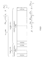
- FIG.2 shows an arrangement example of band for LTE and band for LTE+ in the DL band and UL band according to the present embodiment.
- the "band for LTE” is a band used in an LTE system and the "band for LTE+” is a band used in an LTE+ system.
- the band for LTE and the band for LTE+ are arranged so that their center frequencies overlap.
- an LTE system is operated.
- an SCH (Synchronization CHannel) and BCH for LTE are transmitted in the 10 MHz band where the DL band for LTE and the DL band for LTE+ overlap.
- the base station uses the BCH to report information about the UL band for LTE to the LTE mobile station and the LTE+ mobile station.
- BCH+ for LTE+ is transmitted in the DL band for LTE+. The base station reports information about the band for the LTE+ to the LTE+ mobile station using the BCH+.
- the LTE mobile station receives the BCH transmitted in the 10 MHz band where the DL band for LTE and the DL band for LTE+ overlap and acquires the position of the UL band for LTE.
- the LTE+ mobile station is compatible with the LTE system and is provided with a function similar to the reception function of the LTE mobile station.
- the LTE+ mobile station receives a signal transmitted in the DL band for LTE from the base station using a reception method similar to that of the LTE mobile station. That is, the LTE+ mobile station receives the BCH transmitted in the 10 MHz band where the DL band for LTE and the DL band for LTE+ overlap and acquires the position of the UL band for LTE as in the case of the LTE mobile station. Furthermore, the LTE+ mobile station receives the BCH+ transmitted in the DL band for LTE+ and acquires the position of the UL band for LTE+ from the information about the UL bandwidth for LTE+ included in the BCH+. The method for acquiring the position of the UL band for LTE+ will be described later.
- the DL band for LTE and DL band for LTE+ with their center frequencies overlapping each other, it is possible to accommodate the LTE mobile station and the LTE+ mobile station together in the DL band.
- the band for LTE is arranged in a frequency band lower than the band for LTE+ next to the band for LTE+.
- PUCCHs are arranged at both ends of the UL band for LTE. It is defined in the LTE system that PUCCHs are arranged at both ends of the UL band for LTE. As the number of PUCCHs increases, PUCCHs are sequentially arranged inside the UL band for LTE.
- PUCCH+'s are arranged at both ends of the UL band for LTE+.
- the UL band for LTE is arranged next to a frequency band lower than the UL band for LTE+.
- the LTE+ mobile station uses a BCH to acquire information about the UL band for LTE reported from the base station.
- the bandwidth Fw[MHz] and center frequency fc[MHz] of the UL band for LTE are reported.
- the base station selects the bandwidth Fw from among, for example 1.4 MHz, 3 MHz, 5 MHz, 10 MHz, 15 MHz and 20 MHz according to the communication situation of the mobile station or the like.
- the base station reports a total bandwidth Fw total of the bandwidth Fw of the UL band for LTE and the bandwidth Fw + of the UL band for LTE+ using the BCH+.
- the total bandwidth Fw total is selected from a plurality of candidates, for example, 1.4 MHz, 3 MHz, 5 MHz, 10 MHz, 15 MHz, 20 MHz, 40 MHz, 60 MHz, 80 MHz and 100 MHz.
- the present embodiment arranges the UL band for LTE next to a frequency band lower than the UL band for LTE+.
- the base station reports the bandwidth Fw and center frequency fc of the UL band for LTE using a BCH, and, therefore, if the base station only needs to report the total bandwidth Fw total using the BCH+, the LTE+ mobile station can acquire the center frequency fc+ of the UL band for LTE+ allocated to the LTE+ mobile station using equation 1 without reporting the center frequency fc+ of the UL band for LTE+.
- the LTE+ mobile station can acquire the center frequency fc + of the UL band for LTE+ allocated to the LTE+ mobile station by substituting the bandwidth Fw, center frequency fc and total bandwidth Fw total of the UL band for LTE into equation 1, because the UL band for LTE is arranged next to the frequency band lower than the UL band for LTE+.
- the base station needs only to report the bandwidth Fw, center frequency fc+ and total bandwidth Fw total of the UL band for LTE and need not report the bandwidth Fw+ and center frequency fc + of the UL band for LTE+, and can thereby reduce the amount of signaling for reporting the information about the UL band for LTE+.
- the present embodiment arranges the UL band for LTE next to the frequency band lower than the UL band for LTE+. Adopting such an arrangement prevents the uplink control channel (PUCCH or the like) transmitted by the LTE mobile station from dividing the band for LTE+, and thereby allows wide bands to be allocated to the LTE+ mobile station continuously.
- PUCCH uplink control channel
- the LTE+ mobile station performs single carrier transmission on the uplink, this allows continuous bands to be allocated to a single carrier signal and can thereby reduce PAPR (peak to average power ratio).
- the present embodiment can secure a wide continuous bandwidth and the effect of reduction of PAPR becomes distinct.
- the LTE+ mobile station can acquire the center frequency fc+ of the UL band for LTE+ allocated to the LTE+ mobile station using equation 1.
- the LTE+ mobile station can acquire information about the UL band allocated to the LTE+ mobile station without reporting the center frequency fc+ of the UL band for LTE+ and reduce the amount of signaling for band information reporting.
- the bandwidth Fw tatal which is a total of the bandwidth of the UL band for LTE and the bandwidth of the UL band for LTE+ is selected from among a plurality of candidates (1.4 MHz, 3 MHz, 5 MHz, 10 MHz, 15 MHz, 20 MHz, 40 MHz, 60 MHz, 80 MHz and 100 MHz)
- no more than ten patterns of bandwidth need to be prepared in advance.
- the UL bandwidth for LTE+ is reported, more patterns need to be prepared.
- the base station may report the center frequency fc+ of the UL band for LTE+ using a BCH+ instead of the total bandwidth Fw total .
- FIG.3 shows a relationship between the bandwidth Fw and center frequency fc of the UL band for LTE and the bandwidth Fw + and center frequency fc + of the UL band for LTE+ and total bandwidth Fw total .
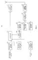
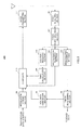
- FIG.4 is a block diagram illustrating a configuration of the mobile station apparatus according to the present embodiment.
- Mobile station apparatus 100 in FIG.4 is applicable to both an LTE mobile station and an LTE+ mobile station.
- Mobile station apparatus 100 in FIG.4 is comprised of radio receiving section 101, signal demultiplexing section 102, demodulation/decoding section 103, error determining section 104, ACK/NACK generation section 105, BCH/BCH+ receiving section 106, PDCCH (Physical Downlink Control Channel)/PDCCH+ receiving section 107, band calculation section 108, modulation/coding section 109, scheduler 110 and radio transmitting section 111.
- radio receiving section 101 signal demultiplexing section 102, demodulation/decoding section 103, error determining section 104, ACK/NACK generation section 105, BCH/BCH+ receiving section 106, PDCCH (Physical Downlink Control Channel)/PDCCH+ receiving section 107, band calculation section 108, modulation/coding section 109, schedule
- Radio receiving section 101 receives a signal transmitted from a base station via an antenna, applies radio processing such as down-conversion and outputs the received signal after the radio processing to signal demultiplexing section 102.
- Signal demultiplexing section 102 demultiplexes the received signal into received data, control information such as a BCH and BCH+ and downlink control channel such as a PDCCH and PDCCH.
- Signal demultiplexing section 102 outputs the received data to demodulation/decoding section 103, outputs control information such as a BCH and BCH+ to BCH/BCH+ receiving section 106 and outputs a downlink control channel such as a PDCCH and PDCCH to PDCCH/PDCCH+ receiving section 107.
- Demodulation/decoding section 103 demodulates/decodes the received signal and outputs the demodulated/decoded received data to error determining section 104.
- Error determining section 104 determines whether or not the received data contains an error and outputs the determination result to ACK/NACK generation section 105.
- ACK/NACK generation section 105 generates ACK when the received data contains no error or generates NACK when the received data contains an error, and outputs the generated ACK/NACK to scheduler 110.
- BCH/BCH+ receiving section 106 extracts information about the center frequency fc and bandwidth Fw of the UL band for LTE and, total bandwidth Fw total according to the inputted control information, and outputs the information to band calculation section 108.
- PDCCH/PDCCH+ receiving section 107 receives a PDCCH or PDCCH+.
- PDCCH/PDCCH+ receiving section 107 determines the transmission position of ACK/NACK in a PUCCH associated with the CCE (Control Channel Element) number of the received PDCCH and outputs information about the determined transmission position to scheduler 110.
- PDCCH/PDCCH+ receiving section 107 determines the transmission position of ACK/NACK in a PUCCH+ associated with the CCE+ number of the received PDCCH+ and outputs information about the determined transmission position to scheduler 110.
- the association between a PDCCH+ and a PUCCH+ will follow the above described basic arrangement example.
- Band calculation section 108 calculates the center frequency fc+ of the UL band for LTE+ and UL bandwidth Fw+ for LTE+ of the UL band for LTE+ using equation 1 and equation 3 and outputs information about the UL bandwidth Fw for LTE, center frequency fc and UL band Fw+ for LTE+ to scheduler 110.
- Fw + Fw total - Fw
- Modulation/coding section 109 modulates/encodes a control signal such as transmission data and CQI, acquires a modulated signal and outputs the modulated signal to scheduler 110.
- Scheduler 110 schedules the modulated signal to an appropriate frequency band. To be more specific, when using an UL band for LTE, scheduler 110 allocates the modulated signal to an appropriate frequency band of the UL band for LTE using information about the bandwidth Fw and center frequency fc of the UL band for LTE. On the other hand, when using a UL band for LTE+, scheduler 110 allocates the modulated signal in an appropriate frequency band of the UL band for LTE+ using information about the bandwidth Fw+ and center frequency fc+ of the UL band for LTE+.
- scheduler 110 stores the association between the PDCCH and PUCCH and the association between the PDCCH+ and PUCCH+ separately. Scheduler 110 then schedules ACK/NACK to data reception in the DL band for LTE to a PUCCH associated with the CCE number of a PDCCH. Furthermore, scheduler 110 schedules ACK/NACK in response to data reception in the DL band for LTE+ to a PUCCH+ associated with the CCE+ number of a PDCCH+.
- Scheduler 110 outputs the scheduled modulated signal to radio transmitting section 111.
- Radio transmitting section 111 applies single carrier modulation to the scheduled modulated signal and transmits a single carrier signal to the base station via an antenna.
- the present embodiment arranges the UL band for LTE next to a frequency band lower than the UL band for LTE+.
- the LTE+ mobile station can acquire the center frequency fc+ of the UL band for LTE+ allocated to the LTE+ mobile station using equation 1.
- the LTE+ mobile station can acquire information about the UL band allocated to the LTE+ mobile station and can thereby reduce the amount of signaling for band information reporting.
- arranging the UL band for LTE in a frequency band lower than the UL band for LTE+ improves channel quality compared to arranging the UL band for LTE i n a frequency band higher than the UL band for LTE+ and can secure excellent communication quality even when the LTE mobile station goes away from the base station.
- the present embodiment will describe an arrangement example of a PUCCH+ different from that of Embodiment 1.
- an LTE mobile station when a PDCCH is transmitted from a base station, an LTE mobile station transmits an ACK/NACK signal corresponding to data reception on a downlink to the base station using a PUCCH corresponding to the CCE number where the PDCCH is arranged.
- the LTE system associates the transmission position of a PDCCH with the transmission position of a PUCCH for transmitting ACK/NACK and operates according to the rule of association.
- Embodiment 1 has described an example where the rule of association between PDCCH and PUCCH in the LTE system is applied to an LTE+ system. That is, PUCCH+'s are arranged at both ends of the UL band for LTE+.
- the present embodiment proposes a new rule of association between PDCCH+ and PUCCH+ and will describe three arrangement examples below.
- the following explanation will assume that two PUCCH+'s are distinctively referred to as a "first PUCCH+” and a "second PUCCH+” and the first PUCCH+ is arranged on a frequency side lower than the second PUCCH+.
- the UL band for LTE is 10 MHz and the UL band for LTE+ is 35 MHz as an example.
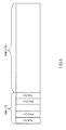
- FIG.5 shows arrangement example 1.
- the first and second PUCCH+'s for LTE+ are arranged inside PUCCH's for LTE.
- the first and second PUCCH+'s for LTE+ next to PUCCH's for LTE and within the UL band for LTE prevents the first and second PUCCH+'s in the UL band for LTE+ from being transmitted. This makes it possible to increase a bandwidth that can be allocated to LTE+ data transmission and transmit more data.
- PDCCH's transmitted on the downlink for LTE and PUCCH's transmitted on the uplink for LTE are associated with each other and the LTE mobile station transmits ACK/NACK using a PUCCH associated with the CCE number where the PDCCH is arranged.
- the first PUCCH+ is arranged next to a PUCCH on the lower frequency side of the UL band for LTE and outside the UL band for LTE and the second PUCCH+ is arranged within the UL band for LTE+.
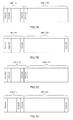
- FIG.6A shows arrangement example 2(a).
- the first PUCCH+ is arranged next to a PUCCH and outside the UL band for LTE. Furthermore, the second PUCCH+ is arranged next to a PUCCH on the higher frequency side and within the UL band for LTE+. In such an arrangement, since the first and second PUCCH+'s are not arranged in the UL band for LTE, it is possible to prevent reduction of the data transmission band in the UL band for LTE compared to arrangement example 1.
- FIG.6B shows arrangement example 2(b).
- the first PUCCH+ is arranged next to a PUCCH on the lower frequency side and outside the UL band for LTE. Furthermore, the second PUCCH+ is arranged at an end of the higher frequency side within the UL band for LTE+. In such an arrangement, since the first PUCCH+ and the second PUCCH+ are arranged farther from each other than in arrangement example 2(a), a better frequency diversity effect can be provided.
- the LTE+ mobile station operates bands from the band in which the first PUCCH+ is arranged to the band in which the second PUCCH+ is arranged as the UL band for LTE+, the PUCCH+'s are transmitted at both ends of the UL band for LTE+, and therefore bands can be operated with the same rule as that of LTE.
- one of the first and second PUCCH+'s is arranged within the UL band for LTE. That is, one of the first and second PUCCH+'s is nested between two PUCCH's.
- the number of PUCCH+'s that occupy the UL band for LTE can be reduced compared to arrangement example 1.
- FIG.7A, FIG.7B, FIG.7C and FIG.7D show arrangement example 3(a), arrangement example 3(b), arrangement example 3(c) and arrangement example 3(d), respectively.
- FIG.7A shows arrangement example 3(a).
- the first and second PUCCH+'s are arranged next to the higher frequency side of two PUCCH's. Such an arrangement eliminates the necessity of transmitting PUCCH+'s outside the band on the lower frequency side of the UL band for LTE and can provide a better frequency diversity effect than arrangement example 1.
- FIG.7B shows arrangement example 3(b).
- the first PUCCH+ is arranged next to the higher frequency side of a PUCCH on the lower frequency side and the second PUCCH+ is arranged at an end on the higher frequency side of the UL band for LTE+.
- the frequency interval between two PUCCH+'s is further widened, a better frequency diversity effect can be provided.
- FIG.7C shows arrangement example 3(c).
- the first and second PUCCH+'s are arranged next to the lower frequency side of two PUCCH's respectively.
- Such an arrangement can continuously secure a wide band as the UL band for LTE+ in the same way as arrangement example 1 and provide a better frequency diversity effect than arrangement example 1.
- the PUCCH+'s need to be transmitted outside the UL band for LTE in the same way as in arrangement example 2.
- FIG.7D shows arrangement example 3(d).
- the first PUCCH+ is arranged next to the lower frequency side of a PUCCH on the higher frequency side and the second PUCCH+ is arranged at an end on the higher frequency side of the UL band for LTE+.
- the frequency interval between two PUCCH+'s is widened and therefore a high frequency diversity effect can be provided.
- FIG.8 is a block diagram illustrating a configuration of main parts of the mobile station apparatus according to the present embodiment. Components of mobile station apparatus 200 in FIG.8 common to those in FIG.4 will be assigned the same reference numerals as those in FIG.4 and descriptions thereof will be omitted. Mobile station apparatus 200 in FIG.8 corresponds to mobile station apparatus 100 in FIG.4 provided with PDCCH/PDCCH+ receiving section 201 instead of PDCCH/PDCCH+ receiving section 107.
- PDCCH/PDCCH+ receiving section 201 receives a PDCCH or PDCCH+.
- PDCCH/PDCCH+ receiving section 201 determines the transmission position of ACK/NACK in a PUCCH associated with the CCE number of the received PDCCH and outputs information about the determined transmission position to scheduler 110.
- PDCCH/PDCCH+ receiving section 201 determines the transmission position of ACK/NACK in the PUCCH+ associated with the CCE+ number of the received PDCCH+ and outputs information about the determined transmission position to scheduler 110.
- the association between the PDCCH+ and the PUCCH+ follows one of arrangement example 1 to arrangement example 3.
- arrangement example 1 to arrangement example 3 as a new rule of association between a PDCCH+ and a PUCCH+.
- Arrangement example 1 to arrangement example 3 can secure transmission data bands in the UL band for LTE+ continuously, and can thereby reduce PAPR when carrying out single carrier transmission.
- PUCCH+'s may be arranged next to the already arranged PUCCH+'s and inside or outside the PUCCH+'s. Furthermore, as the method of arranging PUCCH+'s corresponding to the increment, a combination of aforementioned arrangement example 1 to arrangement example 3 may be used.
- a BCH+ is arranged in the DL band for LTE+ as an example, but without being limited to this, a BCH+ may also be arranged in the DL band for LTE.
- the LTE+ mobile station may also be communicated only in the UL band for LTE+ or may be communicated only in the UL band for LTE or may be communicated using the UL band for LTE+ and the UL band for LTE together.
- Each function block employed in the description of the aforementioned embodiments may typically be implemented as an LSI constituted by an integrated circuit. These may be individual chips or partially or totally contained on a single chip. "LSI” is adopted here but this may also be referred to as “IC,” “system LSI,” “super LSI” or “ultra LSI” depending on differing extents of integration.
- circuit integration is not limited to LSI's, and implementation using dedicated circuitry or general purpose processors is also possible.
- FPGA Field Programmable Gate Array
- reconfigurable processor where connections and settings of circuit cells within an LSI can be reconfigured is also possible.
- the frequency band allocation method and transmitting apparatus according to the present invention is useful as an uplink frequency band allocation method for an LTE system and LTE+ system in a mixed system in which the LTE system and LTE+ system coexist and as a transmitting apparatus applied to a mixed system or the like.
Landscapes
- Engineering & Computer Science (AREA)
- Signal Processing (AREA)
- Computer Networks & Wireless Communication (AREA)
- Mobile Radio Communication Systems (AREA)
Applications Claiming Priority (2)
| Application Number | Priority Date | Filing Date | Title |
|---|---|---|---|
| JP2008204327 | 2008-08-07 | ||
| PCT/JP2009/003778 WO2010016261A1 (ja) | 2008-08-07 | 2009-08-06 | 周波数帯域割当方法及び送信装置 |
Publications (2)
| Publication Number | Publication Date |
|---|---|
| EP2312899A1 true EP2312899A1 (de) | 2011-04-20 |
| EP2312899A4 EP2312899A4 (de) | 2017-11-15 |
Family
ID=41663488
Family Applications (1)
| Application Number | Title | Priority Date | Filing Date |
|---|---|---|---|
| EP09804748.3A Withdrawn EP2312899A4 (de) | 2008-08-07 | 2009-08-06 | Frequenzbandzuordnungsverfahren und übertragungsvorrichtung |
Country Status (5)
| Country | Link |
|---|---|
| US (1) | US8588173B2 (de) |
| EP (1) | EP2312899A4 (de) |
| JP (1) | JP5366951B2 (de) |
| CN (1) | CN102106180A (de) |
| WO (1) | WO2010016261A1 (de) |
Cited By (2)
| Publication number | Priority date | Publication date | Assignee | Title |
|---|---|---|---|---|
| US8737340B2 (en) | 2010-11-26 | 2014-05-27 | Huawei Technologies Co., Ltd. | Power control method and base station |
| EP2916574A4 (de) * | 2012-11-09 | 2016-02-24 | Huawei Tech Co Ltd | Verfahren und basisstation zur gemeinsamen nutzung eines frequenzspektrums |
Families Citing this family (4)
| Publication number | Priority date | Publication date | Assignee | Title |
|---|---|---|---|---|
| KR101089838B1 (ko) * | 2008-08-13 | 2011-12-05 | 한국전자통신연구원 | 캐리어 집성을 사용하는 통신 시스템 및 상기 통신 시스템에 속하는 기지국 및 단말 |
| US8417253B2 (en) | 2010-02-23 | 2013-04-09 | Intel Corporation | Bandwidth and channel notification for wide-channel wireless communication |
| CN106027219B (zh) | 2010-09-03 | 2020-06-23 | 太阳专利托管公司 | 终端装置、通信装置、通信方法和集成电路 |
| KR20140006200A (ko) * | 2012-06-27 | 2014-01-16 | 한국전자통신연구원 | 사물통신 서비스를 위한 데이터 송수신 방법 및 이를 이용한 통신 장치 |
Family Cites Families (12)
| Publication number | Priority date | Publication date | Assignee | Title |
|---|---|---|---|---|
| US5805633A (en) * | 1995-09-06 | 1998-09-08 | Telefonaktiebolaget L M Ericsson | Method and apparatus for frequency planning in a multi-system cellular communication network |
| EP0975184A1 (de) | 1998-07-20 | 2000-01-26 | Motorola, Inc. | Verfahren zur Mittelzuteilung und Zuteilungsschema dafür |
| KR100830163B1 (ko) * | 2005-04-20 | 2008-05-20 | 삼성전자주식회사 | 주파수 오버레이 통신 시스템에서 신호 송수신 장치 및 방법 |
| US8095134B2 (en) * | 2006-10-27 | 2012-01-10 | Nokia Corporation | Method and apparatus for handover measurement |
| JP5074007B2 (ja) | 2006-11-01 | 2012-11-14 | 株式会社エヌ・ティ・ティ・ドコモ | ユーザ端末装置及び基地局装置 |
| JP5202535B2 (ja) * | 2006-11-02 | 2013-06-05 | テレフオンアクチーボラゲット エル エム エリクソン(パブル) | 周波数領域及び時間領域における信号の循環的なシフト |
| KR101236624B1 (ko) * | 2007-02-01 | 2013-02-22 | 삼성전자주식회사 | 이종망간 서비스 연동 방법과 장치 및 시스템 |
| JP4483876B2 (ja) | 2007-02-22 | 2010-06-16 | 日本電気株式会社 | 二重化システムにおける記憶装置の制御方法 |
| WO2008117168A2 (en) * | 2007-03-26 | 2008-10-02 | Nokia Corporation | Method and apparatus for providing high bandwidth utilization |
| US8072918B2 (en) * | 2007-04-03 | 2011-12-06 | Texas Instruments Incorporated | Network-based inter-cell power control for multi-channel wireless networks |
| JP5024533B2 (ja) * | 2007-06-19 | 2012-09-12 | 日本電気株式会社 | 移動通信システムにおけるリファレンス信号系列の割当方法および装置 |
| EP2699052B1 (de) * | 2008-04-07 | 2018-12-05 | Telefonaktiebolaget LM Ericsson (publ) | Verfahren für und Funkübertragungssystem und Funkzugangsgerät für zellulare drahtlose Funkübertragung |
-
2009
- 2009-08-06 JP JP2010523764A patent/JP5366951B2/ja not_active Expired - Fee Related
- 2009-08-06 CN CN2009801291088A patent/CN102106180A/zh active Pending
- 2009-08-06 US US13/057,254 patent/US8588173B2/en not_active Expired - Fee Related
- 2009-08-06 WO PCT/JP2009/003778 patent/WO2010016261A1/ja not_active Ceased
- 2009-08-06 EP EP09804748.3A patent/EP2312899A4/de not_active Withdrawn
Non-Patent Citations (1)
| Title |
|---|
| See references of WO2010016261A1 * |
Cited By (3)
| Publication number | Priority date | Publication date | Assignee | Title |
|---|---|---|---|---|
| US8737340B2 (en) | 2010-11-26 | 2014-05-27 | Huawei Technologies Co., Ltd. | Power control method and base station |
| US8934444B2 (en) | 2010-11-26 | 2015-01-13 | Huawei Technologies Co., Ltd. | Power control method and base station |
| EP2916574A4 (de) * | 2012-11-09 | 2016-02-24 | Huawei Tech Co Ltd | Verfahren und basisstation zur gemeinsamen nutzung eines frequenzspektrums |
Also Published As
| Publication number | Publication date |
|---|---|
| CN102106180A (zh) | 2011-06-22 |
| JP5366951B2 (ja) | 2013-12-11 |
| JPWO2010016261A1 (ja) | 2012-01-19 |
| US20110134870A1 (en) | 2011-06-09 |
| EP2312899A4 (de) | 2017-11-15 |
| WO2010016261A1 (ja) | 2010-02-11 |
| US8588173B2 (en) | 2013-11-19 |
Similar Documents
| Publication | Publication Date | Title |
|---|---|---|
| JP7113258B2 (ja) | 集積回路 | |
| US12225551B2 (en) | Base station, terminal, transmission method, and reception method | |
| US20230036232A1 (en) | Terminal device, base station device, and uplink response signal transmission method | |
| EP2369774B1 (de) | Mobilstation und Basisstationsvorrichtung | |
| CN108810905A (zh) | 传输上行信道的方法和装置及传输下行信道的方法和装置 | |
| US8588173B2 (en) | Frequency band allocation method and transmission device | |
| US20160143032A1 (en) | Base station device, mobile station device, and communication method | |
| US9775070B2 (en) | Integrated circuit |
Legal Events
| Date | Code | Title | Description |
|---|---|---|---|
| PUAI | Public reference made under article 153(3) epc to a published international application that has entered the european phase |
Free format text: ORIGINAL CODE: 0009012 |
|
| 17P | Request for examination filed |
Effective date: 20110202 |
|
| AK | Designated contracting states |
Kind code of ref document: A1 Designated state(s): AT BE BG CH CY CZ DE DK EE ES FI FR GB GR HR HU IE IS IT LI LT LU LV MC MK MT NL NO PL PT RO SE SI SK SM TR |
|
| AX | Request for extension of the european patent |
Extension state: AL BA RS |
|
| DAX | Request for extension of the european patent (deleted) | ||
| RAP1 | Party data changed (applicant data changed or rights of an application transferred) |
Owner name: PANASONIC INTELLECTUAL PROPERTY CORPORATION OF AME |
|
| RA4 | Supplementary search report drawn up and despatched (corrected) |
Effective date: 20171018 |
|
| RIC1 | Information provided on ipc code assigned before grant |
Ipc: H04J 11/00 20060101ALI20171012BHEP Ipc: H04W 72/10 20090101AFI20171012BHEP Ipc: H04J 1/00 20060101ALI20171012BHEP |
|
| STAA | Information on the status of an ep patent application or granted ep patent |
Free format text: STATUS: THE APPLICATION HAS BEEN WITHDRAWN |
|
| 18W | Application withdrawn |
Effective date: 20181204 |