EP2313224B1 - Fraise et insert de coupe pour celle-ci - Google Patents
Fraise et insert de coupe pour celle-ci Download PDFInfo
- Publication number
- EP2313224B1 EP2313224B1 EP09787446.5A EP09787446A EP2313224B1 EP 2313224 B1 EP2313224 B1 EP 2313224B1 EP 09787446 A EP09787446 A EP 09787446A EP 2313224 B1 EP2313224 B1 EP 2313224B1
- Authority
- EP
- European Patent Office
- Prior art keywords
- insert
- major
- cutting edges
- rake
- cutting
- Prior art date
- Legal status (The legal status is an assumption and is not a legal conclusion. Google has not performed a legal analysis and makes no representation as to the accuracy of the status listed.)
- Active
Links
Images




Classifications
-
- B—PERFORMING OPERATIONS; TRANSPORTING
- B23—MACHINE TOOLS; METAL-WORKING NOT OTHERWISE PROVIDED FOR
- B23C—MILLING
- B23C5/00—Milling-cutters
- B23C5/16—Milling-cutters characterised by physical features other than shape
- B23C5/20—Milling-cutters characterised by physical features other than shape with removable cutter bits or teeth or cutting inserts
- B23C5/202—Plate-like cutting inserts with special form
-
- B—PERFORMING OPERATIONS; TRANSPORTING
- B23—MACHINE TOOLS; METAL-WORKING NOT OTHERWISE PROVIDED FOR
- B23C—MILLING
- B23C5/00—Milling-cutters
- B23C5/003—Milling-cutters with vibration suppressing means
-
- B—PERFORMING OPERATIONS; TRANSPORTING
- B23—MACHINE TOOLS; METAL-WORKING NOT OTHERWISE PROVIDED FOR
- B23C—MILLING
- B23C5/00—Milling-cutters
- B23C5/02—Milling-cutters characterised by the shape of the cutter
- B23C5/10—Shank-type cutters, i.e. with an integral shaft
- B23C5/109—Shank-type cutters, i.e. with an integral shaft with removable cutting inserts
-
- B—PERFORMING OPERATIONS; TRANSPORTING
- B23—MACHINE TOOLS; METAL-WORKING NOT OTHERWISE PROVIDED FOR
- B23C—MILLING
- B23C2200/00—Details of milling cutting inserts
- B23C2200/04—Overall shape
- B23C2200/0416—Irregular
-
- B—PERFORMING OPERATIONS; TRANSPORTING
- B23—MACHINE TOOLS; METAL-WORKING NOT OTHERWISE PROVIDED FOR
- B23C—MILLING
- B23C2200/00—Details of milling cutting inserts
- B23C2200/08—Rake or top surfaces
- B23C2200/085—Rake or top surfaces discontinuous
-
- B—PERFORMING OPERATIONS; TRANSPORTING
- B23—MACHINE TOOLS; METAL-WORKING NOT OTHERWISE PROVIDED FOR
- B23C—MILLING
- B23C2210/00—Details of milling cutters
- B23C2210/04—Angles
- B23C2210/0407—Cutting angles
-
- B—PERFORMING OPERATIONS; TRANSPORTING
- B23—MACHINE TOOLS; METAL-WORKING NOT OTHERWISE PROVIDED FOR
- B23C—MILLING
- B23C2210/00—Details of milling cutters
- B23C2210/04—Angles
- B23C2210/0407—Cutting angles
- B23C2210/0414—Cutting angles different
-
- B—PERFORMING OPERATIONS; TRANSPORTING
- B23—MACHINE TOOLS; METAL-WORKING NOT OTHERWISE PROVIDED FOR
- B23C—MILLING
- B23C2210/00—Details of milling cutters
- B23C2210/04—Angles
- B23C2210/0407—Cutting angles
- B23C2210/0442—Cutting angles positive
- B23C2210/045—Cutting angles positive axial rake angle
-
- B—PERFORMING OPERATIONS; TRANSPORTING
- B23—MACHINE TOOLS; METAL-WORKING NOT OTHERWISE PROVIDED FOR
- B23C—MILLING
- B23C2210/00—Details of milling cutters
- B23C2210/04—Angles
- B23C2210/0407—Cutting angles
- B23C2210/0442—Cutting angles positive
- B23C2210/0457—Cutting angles positive radial rake angle
-
- B—PERFORMING OPERATIONS; TRANSPORTING
- B23—MACHINE TOOLS; METAL-WORKING NOT OTHERWISE PROVIDED FOR
- B23C—MILLING
- B23C2210/00—Details of milling cutters
- B23C2210/04—Angles
- B23C2210/0485—Helix angles
- B23C2210/0492—Helix angles different
-
- B—PERFORMING OPERATIONS; TRANSPORTING
- B23—MACHINE TOOLS; METAL-WORKING NOT OTHERWISE PROVIDED FOR
- B23C—MILLING
- B23C2210/00—Details of milling cutters
- B23C2210/32—Details of teeth
- B23C2210/325—Different teeth, i.e. one tooth having a different configuration to a tooth on the opposite side of the flute
-
- B—PERFORMING OPERATIONS; TRANSPORTING
- B23—MACHINE TOOLS; METAL-WORKING NOT OTHERWISE PROVIDED FOR
- B23C—MILLING
- B23C2250/00—Compensating adverse effects during milling
- B23C2250/16—Damping vibrations
-
- Y—GENERAL TAGGING OF NEW TECHNOLOGICAL DEVELOPMENTS; GENERAL TAGGING OF CROSS-SECTIONAL TECHNOLOGIES SPANNING OVER SEVERAL SECTIONS OF THE IPC; TECHNICAL SUBJECTS COVERED BY FORMER USPC CROSS-REFERENCE ART COLLECTIONS [XRACs] AND DIGESTS
- Y10—TECHNICAL SUBJECTS COVERED BY FORMER USPC
- Y10T—TECHNICAL SUBJECTS COVERED BY FORMER US CLASSIFICATION
- Y10T407/00—Cutters, for shaping
- Y10T407/19—Rotary cutting tool
- Y10T407/1906—Rotary cutting tool including holder [i.e., head] having seat for inserted tool
- Y10T407/1908—Face or end mill
-
- Y—GENERAL TAGGING OF NEW TECHNOLOGICAL DEVELOPMENTS; GENERAL TAGGING OF CROSS-SECTIONAL TECHNOLOGIES SPANNING OVER SEVERAL SECTIONS OF THE IPC; TECHNICAL SUBJECTS COVERED BY FORMER USPC CROSS-REFERENCE ART COLLECTIONS [XRACs] AND DIGESTS
- Y10—TECHNICAL SUBJECTS COVERED BY FORMER USPC
- Y10T—TECHNICAL SUBJECTS COVERED BY FORMER US CLASSIFICATION
- Y10T407/00—Cutters, for shaping
- Y10T407/23—Cutters, for shaping including tool having plural alternatively usable cutting edges
-
- Y—GENERAL TAGGING OF NEW TECHNOLOGICAL DEVELOPMENTS; GENERAL TAGGING OF CROSS-SECTIONAL TECHNOLOGIES SPANNING OVER SEVERAL SECTIONS OF THE IPC; TECHNICAL SUBJECTS COVERED BY FORMER USPC CROSS-REFERENCE ART COLLECTIONS [XRACs] AND DIGESTS
- Y10—TECHNICAL SUBJECTS COVERED BY FORMER USPC
- Y10T—TECHNICAL SUBJECTS COVERED BY FORMER US CLASSIFICATION
- Y10T407/00—Cutters, for shaping
- Y10T407/23—Cutters, for shaping including tool having plural alternatively usable cutting edges
- Y10T407/235—Cutters, for shaping including tool having plural alternatively usable cutting edges with integral chip breaker, guide or deflector
Definitions
- the present invention relates to an indexable cutting insert according to the preambles of claim 1 and 8 and a milling cutter with identical indexable cutting inserts according to the preamble of claim 11, for use in metal cutting processes in general and milling cutting processes in particular.
- Such an indexable cutting insert and such a milling cutter is known from US 5 383 750 A .
- vibration or chatter can occur, leading to accelerated tool wear, reduced level of surface finish, and in persistent cases spindle damage.
- To eliminate or reduce these vibrations without resorting to alternative tooling requires adjustment of the operating parameters, including cutting depth, cutting speed and feed rate, which can very often lead to reduced productivity and efficiency.
- US 4,808,044 discloses a face milling cutter, including a cutter body and a plurality of identical cutting inserts detachably mounted in circumferentially spaced pockets formed in the cutter body.
- First and second recesses are formed in alternate pockets, where the first recess has a bottom facing generally in the direction of rotation and the second recess has a bottom slightly inclined relative to the first recess.
- Each insert has a generally quadrilateral shape with four main cutting edges formed at the intersection of a front rake face and four side faces, and a flat rear face which interfaces the recess bottom via a support member and is releasably secured by a wedge member.
- An insert mounted in a pocket with a first recess has a smaller axial rake angle and larger radial rake angle than an insert mounted in an adjacent pocket with a second recess.
- US 6,619,891 discloses a milling tool, including a body and at least one set of circumferentially spaced identical cutting inserts detachably mounted on separate seats, where each set includes at least three cutting inserts.
- Each insert has an active cutting edge situated between a rake surface and a flank surface, where the rake surface faces generally in the direction of rotation and the flank surface faces generally radially outwardly.
- the seats on the tool body are arranged such that one of the cutting inserts has a clearance angle larger than the clearance angle of at least two other inserts in the same set. This combination results in a milling tool where the larger clearance angle insert generates a smoother surface finish with greater precision and the reduced clearance angle inserts tend to dampen vibrations and provide increased stability.
- US 6,997,651 discloses an end mill with a plurality of flutes formed in a cemented carbide cylindrical body, where each flute has an associated peripheral cutting edge and end cutting edge.
- First and second peripheral cutting edges are alternately arranged as viewed in a circumferential direction of the cylindrical body, as too are corresponding first and second end cutting edges.
- the first and second peripheral cutting edges have first and second radial rake angles, and the first and second end cutting edges have first and second axial rake angles.
- the first radial rake angle is larger than the second radial rake angle, and the first axial angle is smaller than the second axial rake angle. This arrangement permits a cutting resistance to be evenly distributed onto all cutting edges of the end mill, thereby preventing chattering.
- an indexable cutting insert comprising:
- an indexable cutting insert comprising:
- FIG. 1 showing an indexable cutting insert 20 which may be manufactured by form pressing and sintering a cemented carbide, such as tungsten carbide, and may be coated or uncoated.
- a cemented carbide such as tungsten carbide
- the cutting insert 20 has an upper surface 22 and an opposing lower surface 24 which defines a lower plane P, with a peripheral side surface 26 extending in between. Upper and lower peripheral edges 28 and 30 are formed at the intersection of the peripheral side surface 26 with the upper surface 22 and lower surface 24, respectively.
- a clamping through bore 32 extends between and opens out to the upper surface 22 and lower surface 24.
- the cutting insert 20 may be indexed around an insert axis A coaxial with the clamping through bore 32.
- the peripheral side surface 26 has opposing first and second side surfaces 34 and 36, and opposing first and second end surfaces 38 and 40.
- Each of the opposing first and second side surfaces 34 and 36 may include identical side abutment surfaces 42 which are substantially planar.
- Each of the opposing first and second end surfaces 38 and 40 may include identical end abutment surfaces 44 which are substantially planar.
- the upper peripheral edge 28 has a first major cutting edge 46 adjacent the first side surface 34 and a second major cutting edge 48 adjacent the second side surface 36.
- the upper peripheral edge 28 may have two identical minor cutting edges 50 adjacent each of the opposing first and second end surfaces 38 and 40, and two identical corner cutting edges 52 joining each of the first and second major cutting edges 46 and 48 with the respective minor cutting edge 50.
- the upper surface 22 has first and second major rake surfaces 54 and 56 adjacent each of the first and second major cutting edges 46 and 48 respectively.
- a first insert axial rake angle ⁇ 1 is present between a line tangential to the first major cutting edge 46 at a first rake point E and the lower plane P
- a second insert axial rake angle ⁇ 2 is present between a line tangential to the second major cutting edge 48 at a second rake point F and the lower plane P, where the first insert axial rake angle ⁇ 1 is greater than the second insert axial rake angle ⁇ 2.
- the first rake point E is on a first index plane P1 which contains the insert axis A
- the second rake point F is on a second index plane P2 which also contains the insert axis A and has an index angle ⁇ with the first index plane P1.
- the first and second insert axial rake angles ⁇ 1 and ⁇ 2 may be substantially constant along the length of the first and second major cutting edges 46 and 48 respectively.
- an "insert axial rake angle" enables the major cutting edges of the indexable cutting insert to be compared at equivalent rake points when the cutting insert is 'in hand'.
- cutter axial rake angle refers to the 'true' axial rake angle as measured between a line tangential to the major cutting edge at a rake point and the longitudinal axis of the milling cutter.
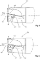
- Figs. 5 and 6 showing a milling cutter 58 with the cutting insert 20 in a first and second index position respectively, removably seated within a given insert receiving pocket 60 of a milling cutter body 62.
- the milling cutter body 62 has three identical insert receiving pockets 60, each insert receiving pocket 60 having a substantially planar pocket seat surface 64 inclined at a same pocket angle ⁇ with a central longitudinal axis C.
- the first major cutting edge 46 is in an active position and has a first cutter axial rake angle ⁇ 1', whereas in Fig.
- the second major cutting edge 48 is in the active position and has a second cutter axial rake angle ⁇ 2', where the first cutter axial rake angle ⁇ 1' is greater than the second cutter axial rake angle ⁇ 2'.
- the first and second cutter axial rake angles ⁇ 1' and ⁇ 2' are measured at rake points on the first and second major cutting edges 46 and 48 respectively, sharing the same radial plane P3 perpendicular to the longitudinal axis C of the milling cutter body 62, and may be substantially constant along the length of the first and second major cutting edges 46 and 48.
- the milling cutter 58 may have, for example, a milling cutter body 62 with three identical insert receiving pockets 60, wherein three identical cutting inserts 20 can be retained in one of two index positions to provide the following possible cutting tool configurations: (i) three cutting inserts 20 having the first major cutting edge 46 with first axial rake angle ⁇ 1' active; (ii) three cutting inserts 20 having the second major cutting edge 48 with second axial rake angle ⁇ 2' active; (iii) two cutting inserts 20 having the first major cutting edge 46 with first cutter axial rake angle ⁇ 1' active and one cutting insert 20 having the second major cutting edge 48 with second cutter axial rake angle ⁇ 2' active; and (iv) one cutting insert 20 having the first major cutting edge 46 with first cutter axial rake angle ⁇ 1' active and two cutting inserts 20 having the second major cutting edge 48 with second cutter axial rake angle ⁇ 2' active.
- the most appropriate cutting tool configuration with respect to different combinations of cutter axial rake angles can be selected using a single set of identical cutting inserts 20.
- configurations (iii) and (iv) could be used to reduce/eliminate chatter whilst providing optimized operating parameters.
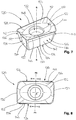
- FIGs. 7 and 8 showing an indexable cutting insert 120 with an upper surface 122 and an opposing lower surface 124 which defines a lower plane P', and a peripheral side surface 126 extending in between.
- Upper and lower peripheral edges 128 and 130 are formed at the intersection of the peripheral side surface 126 with the upper surface 122 and lower surface 124, respectively.
- a clamping through bore 132 extends between and opens out to the upper surface 122 and lower surface 124.
- the cutting insert 120 may be indexed around an insert axis B coaxial with the clamping through bore 132.
- the peripheral side surface 126 has opposing first and second side surfaces 134 and 136, and opposing first and second end surfaces 138 and 140.
- Each of the opposing first and second side surfaces 134 and 136 may include identical side abutment surfaces 142 which are substantially planar.
- Each of the opposing first and second end surfaces 138 and 140 may include identical end abutment surfaces 144 which are substantially planar.
- the upper peripheral edge 128 has a first major cutting edge 146 adjacent the first side surface 134 and a second major cutting edge 148 adjacent the second side surface 136.
- the upper peripheral edge 128 may have two identical minor cutting edges 150 adjacent each of the opposing first and second end surfaces 138 and 140, and two identical corner cutting edges 152 joining each of the first and second major cutting edges 146 and 148 with the respective minor cutting edge 150.
- the upper surface 122 includes first and second major rake surfaces 154 and 156 adjacent each of the first and second major cutting edges 146 and 148 respectively.
- a first rake surface profile angle ⁇ 1 is present between a first line L1 collinear with a cross section profile of the first major rake surface 154, at least in the vicinity of the first major cutting edge 146, and the lower plane P'
- a second rake surface profile angle ⁇ 2 is present between a second line L2 collinear with a cross section profile of the second major rake surface 156, at least in the vicinity of the second major cutting edge 148, and the lower plane P'.
- the first and second lines L1 and L2 lie on first and second central planes P4 and P5 which contain the insert axis B and are perpendicular to the first and second major cutting edges 146 and 148, respectively.
- rake surface profile angle enables the rake surfaces of the indexable cutting insert to be compared at equivalent cross sections when the cutting insert is 'in hand'. It should be understood that the definition of a "rake surface profile angle” can also apply to rake surfaces immediately adjacent cutting edges referred to as 'lands'.
- cutter radial rake angle refers to the 'true' radial rake angle as measured at a section passing through a point anywhere along a major cutting edge as the angle between its associated rake surface and a radius with respect to the axis of the milling cutter.
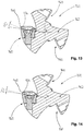
- Figs. 11 , 13 and 12 , 14 show a milling cutter 158 with the cutting insert 120 in a first and second index position respectively, removably seated within a given insert receiving pocket 160 of a milling cutter body 162.
- the milling cutter body 162 has three identical insert receiving pockets 160, each insert receiving pocket 160 having a substantially planar pocket seat surface 164 inclined at a same pocket angle ⁇ ' with a central longitudinal axis D.
- the first major rake surface 154 is in an active position and has a first cutter radial rake angle ⁇ 1, which is substantially constant along the first major cutting edge 146, whereas in Fig.
- the second major rake surface 156 is in the active position and has a second cutter radial rake angle ⁇ 2, which is substantially constant along the second major cutting edge 148, where the first cutter radial rake angle ⁇ 1 is greater than the second cutter radial rake angle ⁇ 2.
- the milling cutter 158 may have, for example, a milling cutter body 162 with three identical insert receiving pockets 160, wherein three identical cutting inserts 120 can be retained in one of two index positions to provide the following possible cutting tool configurations: (i) three cutting inserts 120 having the first major rake surface 154 with first cutter radial rake angle ⁇ 1 active; (ii) three cutting inserts 120 having the second major rake surface 156 with second cutter radial rake angle ⁇ 2 active; (iii) two cutting inserts 120 having the first major rake surface 154 with first cutter radial rake angle ⁇ 1 active and one cutting insert 120 having the second major rake surface 156 with second cutter radial rake angle ⁇ 2 active; and (iv) one cutting insert 120 having the first major rake surface 154 with first cutter radial rake angle ⁇ 1 active and two cutting inserts 120 having the second major rake surface 156 with second cutter radial rake angle ⁇ 2 active.
- the most appropriate cutting tool configuration with respect to different combinations of cutter radial rake angles can be selected using a single set of identical cutting inserts 120
- configurations (iii) and (iv) could be used to reduce/eliminate chatter whilst providing optimized operating parameters.
Landscapes
- Engineering & Computer Science (AREA)
- Mechanical Engineering (AREA)
- Milling Processes (AREA)
Claims (15)
- Plaquette de coupe indexable (20, 120), comprenant :une surface supérieure (22, 122) et une surface inférieure opposée (24, 124), avec une surface latérale périphérique (26, 126) s'étendant entre celles-ci ;un alésage traversant de serrage (32, 132) s'étendant entre la surface supérieure (22, 122) et la surface inférieure (24, 124) et débouchant sur celles-ci, ledit alésage traversant de serrage (32, 132) présentant un axe de plaquette A, B autour duquel la plaquette de coupe (20, 120) est indexable ;au moins deux arêtes de coupe principales (46, 146 ; 48, 148) formées sur un bord périphérique supérieur (28, 128) à l'intersection de la surface supérieure (22, 122) et de la surface latérale périphérique (26, 126),avec au moins deux plans d'indexation P1, P2 comprenant l'axe de plaquette A, B et les au moins deux arêtes de coupe principales (46, 146 ; 48, 148) ;au moins deux points d'attaque E, F où lesdits au moins deux plans d'indexation P1, P2 coupent les au moins deux arêtes de coupe principales (46, 146 ; 48, 148) ; etau moins deux angles de coupe axiaux de plaquette α1, α2 entre des lignes tangentielles aux au moins deux arêtes de coupe principales (46, 146 ; 48, 148) sur les au moins deux points d'attaque E, F et un plan inférieur P, P' défini par la surface inférieure (24, 124), un angle d'indexation Ψ égal à 360°/n étant présenté entre les au moins deux plans d'indexation P1, P2, n étant le nombre d'arêtes de coupe principales (46, 146 ; 48, 148), caractériséeen ce qu'au moins deux des au moins deux angles de coupe axiaux de plaquette α1, α2 sont différents.
- Plaquette de coupe (20, 120) selon la revendication 1, comportant au moins deux surfaces de coupe principales (54, 154 ; 56, 156) formées sur la surface supérieure (22, 122), adjacentes à chacune des au moins deux arêtes de coupe principales (46, 146 ; 48, 148) ;
au moins deux plans centraux P4, P5 comprenant l'axe de plaquette A, B et perpendiculaires auxdites au moins deux arêtes de coupe principales (46, 146 ; 48, 148) ; et
au moins deux angles de profil de surface de coupe β1, β2 entre les lignes L1, L2, colinéaires au moins à proximité des au moins deux arêtes de coupe principales (46, 146 ; 48, 148), les profils de section transversale des au moins deux surfaces de coupe principales (54, 154 ; 56, 156) passant par les au moins deux plans centraux P4, P5 et le plan inférieur P, P',
où au moins deux des au moins deux angles de profil de surface de coupe β1, β2 sont différents. - Plaquette de coupe (20, 120) selon la revendication 1, où la surface latérale périphérique (26, 126) comprend une première et une deuxième surfaces latérales opposées (34, 134 ; 36, 136) et une première et une deuxième surfaces d'extrémité opposées (38, 40 ; 138, 140).
- Plaquette de coupe (20, 120) selon la revendication 3, où les au moins deux arêtes de coupe principales (46, 146 ; 48, 148) sont formées le long de parties du bord périphérique supérieur (28, 128) adjacentes à la première et à la deuxième surfaces latérales (34, 134 ; 36, 136).
- Plaquette de coupe (20, 120) selon la revendication 1, comprenant :deux arêtes de coupe principales (46, 146 ; 48, 148) ;où :chacune des deux arêtes de coupe principales (46, 146 ; 48, 148) a une arête de coupe secondaire (50, 150) associée formée sur le bord périphérique supérieur (28, 128).
- Plaquette de coupe (20, 120) selon la revendication 5, où chacune des deux arêtes de coupe principales (46, 146 ; 48, 148) et chacune des deux arêtes de coupe secondaires (50, 150) ont une arête de coupe de coin (52, 152) commune.
- Plaquette de coupe (20, 120) selon la revendication 6, où les deux arêtes de coupe secondaires (50, 150) et les deux arêtes de coupe de coin (52, 152) sont identiques.
- Plaquette de coupe indexable (20, 120), comprenant :une surface supérieure (22, 122) et une surface inférieure opposée (24, 124), avec une surface latérale périphérique (26, 126) s'étendant entre celles-ci ;un alésage traversant de serrage (32, 132) s'étendant entre la surface supérieure (22, 122) et la surface inférieure (24, 124) et débouchant sur celles-ci, ledit alésage traversant de serrage (32, 132) présentant un axe de plaquette A, B autour duquel la plaquette de coupe (20, 120) est indexable ;au moins deux arêtes de coupe principales (46, 146 ; 48, 148) formées sur un bord périphérique supérieur (28, 128) à l'intersection de la surface supérieure (22, 122) et de la surface latérale périphérique (26, 126) ;au moins deux surfaces de coupe principales (54, 154 ; 56, 156) formées sur la surface supérieure (22, 122), adjacentes à chacune des au moins deux arêtes de coupe principales (46, 146 ; 48, 148),avec au moins deux plans centraux P4, P5 comprenant l'axe de plaquette A, B et perpendiculaires auxdites au moins deux arêtes de coupe principales (46, 146 ; 48, 148) ; etau moins deux angles de profil de surface de coupe β1, β2 entre les lignes L1, L2, colinéaires au moins à proximité des au moins deux arêtes de coupe principales (46, 146 ; 48, 148), les profils de section transversale des au moins deux surfaces de coupe principales (54, 154 ; 56, 156) passant par les au moins deux plans centraux P4, P5 et un plan inférieur P, P' défini par la surface inférieure (24, 124),caractériséeen ce qu'au moins deux des au moins deux angles de profil de surface de coupe β1, β2 sont différents.
- Plaquette de coupe (20, 120) selon la revendication 8, ayant au moins deux plans d'indexation P1, P2 comprenant l'axe de plaquette A, B et les au moins deux arêtes de coupe principales (46, 146 ; 48, 148) ;
au moins deux points d'attaque E, F où les au moins deux plans d'indexation P1, P2 coupent les au moins deux arêtes de coupe principales (46, 146 ; 48, 148) ; et
au moins deux angles de coupe axiaux de plaquette α1, α2 entre lignes tangentielles aux
au moins deux arêtes de coupe principales (46, 146 ; 48, 148) sur les au moins deux points d'attaque E, F et le plan inférieur P, P',
où un angle d'indexation ψ égal à 360°/n est présenté entre les au moins deux plans d'indexation P1, P2, n étant le nombre d'arêtes de coupe principales (46, 146 ; 48, 148), et
où au moins deux des au moins deux angles de coupe axiaux de plaquette α1, α2 sont différents. - Plaquette de coupe (20, 120) selon les revendications 1 et 9, où les au moins deux angles de coupe axiaux de plaquette α1, α2 sont sensiblement constants sur la longueur des au moins deux arêtes de coupe principales (46, 146 ; 48, 148).
- Fraise (58, 158) comprenant :un corps de fraise (62, 162) présentant une pluralité de poches de réception de plaquette (60, 160) et un nombre égal de plaquettes de coupe indexables (20, 120) identiques, chaque poche de réception de plaquette (60, 160) ayant une surface d'assise de poche (64, 164) sensiblement plane, inclinée suivant un même angle de poche θ, θ' avec un axe longitudinal central C, D ; etchaque plaquette de coupe indexable (20, 120) identique étant logée de manière amovible dans une poche de la pluralité de poches de réception de plaquette (60, 160), avec au moins :deux arêtes de coupe principales (46, 146 ; 48, 148) comprenant une arête de coupe principale active (46, 146 ; 48, 148) ; etdeux surfaces de coupe principales associées (54, 154 ; 56, 156) comprenant une surface de coupe principale active (54, 154 ; 56, 156),caractériséeen ce que dans un plan radial P3 perpendiculaire à l'axe longitudinal central C,D, au moins deux des plaquettes de coupe (20, 120) identiques présentent :des angles de coupe axiaux d'amplitudes dissemblables α1', α2';et/ou des angles de coupe radiaux d'amplitudes dissemblables δ1, δ2.
- Fraise (58, 158) selon la revendication 11, où le corps de fraise (62, 162) a une pluralité de poches de réception de plaquette (60, 160) identiques.
- Fraise (58, 158) selon la revendication 11, où les angles de coupe radiaux de plaquette δ1, δ2 associés auxdites au moins deux plaquettes de coupe (20, 120) identiques sont sensiblement constants sur la longueur des au moins deux arêtes de coupe principales actives (46, 146 ; 48, 148).
- Fraise (58, 158) selon la revendication 11, où les angles de coupe axiaux α1', α2' associés auxdites au moins deux plaquettes de coupe (20, 120) identiques sont sensiblement constants sur la longueur des au moins deux arêtes de coupe principales actives (46, 146 ; 48, 148).
- Fraise (58, 158) selon la revendication 11, où chaque poche de la pluralité de poches de réception de plaquette (60, 160) est directement adjacente à une surface d'extrémité avant du corps de fraise (62, 162).
Priority Applications (1)
| Application Number | Priority Date | Filing Date | Title |
|---|---|---|---|
| PL09787446T PL2313224T3 (pl) | 2008-08-06 | 2009-06-28 | Frez i wkładka skrawająca do niego |
Applications Claiming Priority (2)
| Application Number | Priority Date | Filing Date | Title |
|---|---|---|---|
| IL193284A IL193284A (en) | 2008-08-06 | 2008-08-06 | Milling cutter and cutting insert therefor |
| PCT/IL2009/000638 WO2010016052A1 (fr) | 2008-08-06 | 2009-06-28 | Fraise et insert de coupe pour celle-ci |
Publications (2)
| Publication Number | Publication Date |
|---|---|
| EP2313224A1 EP2313224A1 (fr) | 2011-04-27 |
| EP2313224B1 true EP2313224B1 (fr) | 2018-01-24 |
Family
ID=41165499
Family Applications (1)
| Application Number | Title | Priority Date | Filing Date |
|---|---|---|---|
| EP09787446.5A Active EP2313224B1 (fr) | 2008-08-06 | 2009-06-28 | Fraise et insert de coupe pour celle-ci |
Country Status (14)
| Country | Link |
|---|---|
| US (1) | US8172487B2 (fr) |
| EP (1) | EP2313224B1 (fr) |
| JP (1) | JP5491505B2 (fr) |
| KR (1) | KR101569551B1 (fr) |
| CN (2) | CN102112259B (fr) |
| BR (1) | BRPI0915569B1 (fr) |
| CA (1) | CA2731348C (fr) |
| ES (1) | ES2663534T3 (fr) |
| IL (1) | IL193284A (fr) |
| PL (1) | PL2313224T3 (fr) |
| PT (1) | PT2313224T (fr) |
| RU (1) | RU2483844C2 (fr) |
| TW (1) | TW201008681A (fr) |
| WO (1) | WO2010016052A1 (fr) |
Families Citing this family (23)
| Publication number | Priority date | Publication date | Assignee | Title |
|---|---|---|---|---|
| SE534715C2 (sv) * | 2010-03-23 | 2011-11-29 | Sandvik Intellectual Property | Fräs samt frässkär härför |
| JP2012152868A (ja) * | 2011-01-27 | 2012-08-16 | Mitsubishi Materials Corp | 切削インサートおよび刃先交換式切削工具 |
| DE102011117148B4 (de) * | 2011-10-28 | 2022-05-05 | Kennametal Inc. | Rotationswerkzeug sowie Verfahren zum Herstellen eines Rotationswerkzeuges sowie eines Schneideinsatzes |
| CN107297531B (zh) * | 2011-10-31 | 2019-11-22 | 京瓷株式会社 | 切削镶刀 |
| JP2013215858A (ja) * | 2012-04-11 | 2013-10-24 | Dijet Industrial Co Ltd | ラジアスエンドミル |
| RU2492974C1 (ru) * | 2012-06-20 | 2013-09-20 | Нина Алексеевна Корюкина | Сборная торцовая фреза |
| RU2494841C1 (ru) * | 2012-07-25 | 2013-10-10 | Нина Алексеевна Корюкина | Сборная торцовая фреза |
| USD738412S1 (en) * | 2013-12-25 | 2015-09-08 | Taegutec Ltd. | Cutting insert |
| RU2562195C1 (ru) * | 2014-03-04 | 2015-09-10 | Общество с ограниченной ответственнстью "Сборные конструкции инструмента, фрезы Москвитина" | Фреза (варианты) |
| USD752664S1 (en) * | 2014-09-25 | 2016-03-29 | Taegutec Ltd. | Cutting insert |
| RU2583975C1 (ru) * | 2014-12-23 | 2016-05-10 | Общество с ограниченной ответственностью "Сборные конструкции инструмента, фрезы Москвитина" | Дисковая фреза (варианты) и режущая пластина для нее |
| USD778330S1 (en) | 2015-07-16 | 2017-02-07 | Kennametal Inc. | Double-sided tangential cutting insert |
| USD777230S1 (en) | 2015-07-16 | 2017-01-24 | Kennametal Inc | Double-sided tangential cutting insert |
| US9981323B2 (en) | 2015-07-16 | 2018-05-29 | Kennametal Inc. | Double-sided tangential cutting insert and cutting tool system using the same |
| JP6817717B2 (ja) | 2016-04-07 | 2021-01-20 | 三菱マテリアル株式会社 | フライスカッタ、切削インサート及びフライス加工方法 |
| KR101941973B1 (ko) | 2017-04-11 | 2019-01-24 | 한국야금 주식회사 | 고이송 절삭 인서트 및 이를 장착한 절삭 공구 |
| CN107350530B (zh) * | 2017-08-31 | 2024-01-23 | 炎陵欧科亿数控精密刀具有限公司 | 一种用于大进给铣削的可转位刀片 |
| JP6508620B1 (ja) * | 2017-10-25 | 2019-05-08 | 株式会社タンガロイ | 切削インサート及び刃先交換式転削工具 |
| CN107876847A (zh) * | 2017-11-20 | 2018-04-06 | 中山市园丰精密刃具有限公司 | 一种双头组合铣刀 |
| CN107812993A (zh) * | 2017-11-21 | 2018-03-20 | 中山市园丰精密刃具有限公司 | 一种手机音量键用铣刀 |
| TWI768131B (zh) * | 2017-11-30 | 2022-06-21 | 以色列商艾斯卡公司 | 單側四向可轉位正切削刀塊及其插銑件 |
| EP3950196A4 (fr) * | 2019-03-27 | 2022-05-25 | Sumitomo Electric Hardmetal Corp. | Insert de coupe |
| CN114769689B (zh) * | 2022-05-30 | 2023-12-29 | 山东理工大学 | 渐进式斜线切削刃微细钻铣刀 |
Family Cites Families (26)
| Publication number | Priority date | Publication date | Assignee | Title |
|---|---|---|---|---|
| SU1423291A1 (ru) * | 1986-04-09 | 1988-09-15 | Сестрорецкий Инструментальный Завод Им.Воскова | Режуща пластина |
| US4808044A (en) * | 1986-04-30 | 1989-02-28 | Mitsubishi Kinzoku Kabushiki Kaisha | Insert cutter |
| IL93883A (en) * | 1989-04-12 | 1993-02-21 | Iscar Ltd | Cutting insert for a milling cutting tool |
| JP2833283B2 (ja) * | 1991-09-05 | 1998-12-09 | 三菱マテリアル株式会社 | スローアウェイチップ |
| IL101985A (en) * | 1992-05-25 | 1996-12-05 | Iscar Ltd | Exchangeable milling cutting inserts |
| DE9320349U1 (de) | 1992-05-25 | 1994-08-04 | Iscar Ltd., Migdal Tefen | Auswechselbare Fräser-Schneideinsätze |
| US5388932A (en) * | 1993-09-13 | 1995-02-14 | Kennametal Inc. | Cutting insert for a milling cutter |
| EP0796162B1 (fr) * | 1994-12-10 | 1998-04-15 | KENNAMETAL HERTEL AG Werkzeuge + Hartstoffe | Outil de per age pour materiau metallique massif |
| US5810519A (en) * | 1995-03-17 | 1998-09-22 | Kennametal Inc. | Helical cutting insert with offset cutting edges |
| US5853267A (en) * | 1996-08-22 | 1998-12-29 | Iscar Ltd. | Cutting insert |
| SE512040C2 (sv) * | 1998-05-06 | 2000-01-17 | Sandvik Ab | Vändskär för pinnfräsar |
| SE514014C2 (sv) * | 1998-05-06 | 2000-12-11 | Sandvik Ab | Vändskär för roterande fräsverktyg |
| SE514032C2 (sv) * | 1998-09-08 | 2000-12-11 | Seco Tools Ab | Verktyg och skär för fräsning |
| SE516252C2 (sv) * | 2000-04-28 | 2001-12-10 | Sandvik Ab | Fräsverktyg innefattande en roterbar kropp samt tangentiellt åtskilda skärorgan |
| IL141089A (en) * | 2001-01-25 | 2006-08-20 | Amir Satran | Cutting insert |
| IL150015A (en) * | 2002-06-04 | 2007-06-17 | Amir Satran | Cutting insert and milling cutter |
| JP4313579B2 (ja) * | 2003-01-22 | 2009-08-12 | オーエスジー株式会社 | スクエアエンドミル |
| IL155288A (en) * | 2003-04-08 | 2007-09-20 | Amir Satran | Tangential cutting insert and milling cutter |
| US7771142B2 (en) * | 2003-05-09 | 2010-08-10 | Kennametal Inc. | Cutting insert with elliptical cutting edge |
| US7399146B2 (en) * | 2003-09-29 | 2008-07-15 | Kennametal Inc. | Rotary cutting tool having irregular insert orientation |
| CN2649237Y (zh) * | 2003-11-04 | 2004-10-20 | 哈尔滨理工大学 | 准三维封闭槽圆弧修光刃、过渡刃可转位铣刀片 |
| US7070363B2 (en) * | 2004-07-15 | 2006-07-04 | Kennametal Inc. | Cutting insert for high-speed milling cutter |
| US7104735B2 (en) * | 2004-09-02 | 2006-09-12 | Ingersoll Cutting Tool Company | Tangential cutting insert and milling cutter |
| US7452167B2 (en) * | 2004-11-26 | 2008-11-18 | Kyocera Corporation | Cutting insert and milling tool |
| RU2284249C1 (ru) * | 2005-05-23 | 2006-09-27 | Нина Алексеевна Корюкина | Тангенциальная режущая пластина |
| JP4971649B2 (ja) * | 2006-02-28 | 2012-07-11 | 京セラ株式会社 | 切削工具 |
-
2008
- 2008-08-06 IL IL193284A patent/IL193284A/en active IP Right Grant
- 2008-08-27 TW TW097132768A patent/TW201008681A/zh unknown
-
2009
- 2009-06-19 US US12/488,326 patent/US8172487B2/en active Active
- 2009-06-28 JP JP2011521682A patent/JP5491505B2/ja active Active
- 2009-06-28 ES ES09787446.5T patent/ES2663534T3/es active Active
- 2009-06-28 BR BRPI0915569A patent/BRPI0915569B1/pt active IP Right Grant
- 2009-06-28 CN CN200980129725.8A patent/CN102112259B/zh active Active
- 2009-06-28 WO PCT/IL2009/000638 patent/WO2010016052A1/fr not_active Ceased
- 2009-06-28 CA CA2731348A patent/CA2731348C/fr active Active
- 2009-06-28 PL PL09787446T patent/PL2313224T3/pl unknown
- 2009-06-28 EP EP09787446.5A patent/EP2313224B1/fr active Active
- 2009-06-28 KR KR1020117002651A patent/KR101569551B1/ko active Active
- 2009-06-28 RU RU2011108547/02A patent/RU2483844C2/ru active
- 2009-06-28 CN CN201210582143.9A patent/CN103028770B/zh active Active
- 2009-06-28 PT PT97874465T patent/PT2313224T/pt unknown
Also Published As
| Publication number | Publication date |
|---|---|
| US20100034601A1 (en) | 2010-02-11 |
| KR20110050633A (ko) | 2011-05-16 |
| RU2011108547A (ru) | 2012-09-20 |
| BRPI0915569B1 (pt) | 2020-12-22 |
| CN102112259B (zh) | 2014-01-01 |
| JP2011530415A (ja) | 2011-12-22 |
| PT2313224T (pt) | 2018-02-19 |
| CN102112259A (zh) | 2011-06-29 |
| CA2731348C (fr) | 2016-08-09 |
| CN103028770B (zh) | 2015-06-17 |
| IL193284A (en) | 2014-06-30 |
| WO2010016052A1 (fr) | 2010-02-11 |
| RU2483844C2 (ru) | 2013-06-10 |
| PL2313224T3 (pl) | 2018-05-30 |
| ES2663534T3 (es) | 2018-04-13 |
| CN103028770A (zh) | 2013-04-10 |
| US8172487B2 (en) | 2012-05-08 |
| KR101569551B1 (ko) | 2015-11-16 |
| EP2313224A1 (fr) | 2011-04-27 |
| TW201008681A (en) | 2010-03-01 |
| JP5491505B2 (ja) | 2014-05-14 |
| CA2731348A1 (fr) | 2010-02-11 |
| BRPI0915569A2 (pt) | 2019-08-27 |
Similar Documents
| Publication | Publication Date | Title |
|---|---|---|
| EP2313224B1 (fr) | Fraise et insert de coupe pour celle-ci | |
| EP3299102B1 (fr) | Corps d'outil en combinaison avec un premier insert de coupe et un deuxième insert de coupe | |
| EP2682212B1 (fr) | Patin de guidage et outil de coupe | |
| EP2902144B1 (fr) | Plaquette de coupe et instrument de coupe rotatif du type à remplacement d'arête de coupe | |
| US7008146B2 (en) | Milling cutter with tangentially mounted inserts | |
| US6619891B2 (en) | Milling tool having cutting members with different clearance angles | |
| US11052465B2 (en) | Turning insert | |
| JPH0957519A (ja) | 3次元加工用エンドミル及びそのチップ | |
| US20240198437A1 (en) | Metal cutting milling tool | |
| KR102316725B1 (ko) | 다결정다이아몬드 소재의 절삭날이 결합된 엔드밀 | |
| JP4378307B2 (ja) | 軸方向送り刃先交換式工具 | |
| JP2008100316A (ja) | 切削工具及び仕上げ刃インサート | |
| US20240131602A1 (en) | Metal cutting milling tool | |
| JP2026056015A (ja) | 刃先交換式転削工具及びホルダ | |
| JP2026055843A (ja) | 刃先交換式転削工具及びホルダ | |
| JP2007130739A (ja) | 穴加工工具 | |
| JP2007069306A (ja) | 切削工具及びインサート | |
| CN121693402A (zh) | 切削刀片及可转位刀片式立铣刀 |
Legal Events
| Date | Code | Title | Description |
|---|---|---|---|
| PUAI | Public reference made under article 153(3) epc to a published international application that has entered the european phase |
Free format text: ORIGINAL CODE: 0009012 |
|
| 17P | Request for examination filed |
Effective date: 20110302 |
|
| AK | Designated contracting states |
Kind code of ref document: A1 Designated state(s): AT BE BG CH CY CZ DE DK EE ES FI FR GB GR HR HU IE IS IT LI LT LU LV MC MK MT NL NO PL PT RO SE SI SK TR |
|
| AX | Request for extension of the european patent |
Extension state: AL BA RS |
|
| DAX | Request for extension of the european patent (deleted) | ||
| GRAP | Despatch of communication of intention to grant a patent |
Free format text: ORIGINAL CODE: EPIDOSNIGR1 |
|
| INTG | Intention to grant announced |
Effective date: 20170626 |
|
| GRAJ | Information related to disapproval of communication of intention to grant by the applicant or resumption of examination proceedings by the epo deleted |
Free format text: ORIGINAL CODE: EPIDOSDIGR1 |
|
| GRAL | Information related to payment of fee for publishing/printing deleted |
Free format text: ORIGINAL CODE: EPIDOSDIGR3 |
|
| GRAS | Grant fee paid |
Free format text: ORIGINAL CODE: EPIDOSNIGR3 |
|
| GRAP | Despatch of communication of intention to grant a patent |
Free format text: ORIGINAL CODE: EPIDOSNIGR1 |
|
| INTC | Intention to grant announced (deleted) | ||
| GRAA | (expected) grant |
Free format text: ORIGINAL CODE: 0009210 |
|
| INTG | Intention to grant announced |
Effective date: 20171205 |
|
| AK | Designated contracting states |
Kind code of ref document: B1 Designated state(s): AT BE BG CH CY CZ DE DK EE ES FI FR GB GR HR HU IE IS IT LI LT LU LV MC MK MT NL NO PL PT RO SE SI SK TR |
|
| REG | Reference to a national code |
Ref country code: GB Ref legal event code: FG4D |
|
| REG | Reference to a national code |
Ref country code: CH Ref legal event code: EP |
|
| REG | Reference to a national code |
Ref country code: AT Ref legal event code: REF Ref document number: 965502 Country of ref document: AT Kind code of ref document: T Effective date: 20180215 Ref country code: CH Ref legal event code: NV Representative=s name: VOSSIUS AND PARTNER PATENTANWAELTE RECHTSANWAE, CH |
|
| REG | Reference to a national code |
Ref country code: PT Ref legal event code: SC4A Ref document number: 2313224 Country of ref document: PT Date of ref document: 20180219 Kind code of ref document: T Free format text: AVAILABILITY OF NATIONAL TRANSLATION Effective date: 20180209 |
|
| REG | Reference to a national code |
Ref country code: IE Ref legal event code: FG4D |
|
| REG | Reference to a national code |
Ref country code: DE Ref legal event code: R096 Ref document number: 602009050569 Country of ref document: DE |
|
| REG | Reference to a national code |
Ref country code: ES Ref legal event code: FG2A Ref document number: 2663534 Country of ref document: ES Kind code of ref document: T3 Effective date: 20180413 |
|
| REG | Reference to a national code |
Ref country code: SE Ref legal event code: TRGR |
|
| REG | Reference to a national code |
Ref country code: NL Ref legal event code: MP Effective date: 20180124 |
|
| REG | Reference to a national code |
Ref country code: LT Ref legal event code: MG4D |
|
| REG | Reference to a national code |
Ref country code: FR Ref legal event code: PLFP Year of fee payment: 10 |
|
| PG25 | Lapsed in a contracting state [announced via postgrant information from national office to epo] |
Ref country code: NL Free format text: LAPSE BECAUSE OF FAILURE TO SUBMIT A TRANSLATION OF THE DESCRIPTION OR TO PAY THE FEE WITHIN THE PRESCRIBED TIME-LIMIT Effective date: 20180124 |
|
| PG25 | Lapsed in a contracting state [announced via postgrant information from national office to epo] |
Ref country code: LT Free format text: LAPSE BECAUSE OF FAILURE TO SUBMIT A TRANSLATION OF THE DESCRIPTION OR TO PAY THE FEE WITHIN THE PRESCRIBED TIME-LIMIT Effective date: 20180124 Ref country code: CY Free format text: LAPSE BECAUSE OF FAILURE TO SUBMIT A TRANSLATION OF THE DESCRIPTION OR TO PAY THE FEE WITHIN THE PRESCRIBED TIME-LIMIT Effective date: 20180124 Ref country code: FI Free format text: LAPSE BECAUSE OF FAILURE TO SUBMIT A TRANSLATION OF THE DESCRIPTION OR TO PAY THE FEE WITHIN THE PRESCRIBED TIME-LIMIT Effective date: 20180124 Ref country code: NO Free format text: LAPSE BECAUSE OF FAILURE TO SUBMIT A TRANSLATION OF THE DESCRIPTION OR TO PAY THE FEE WITHIN THE PRESCRIBED TIME-LIMIT Effective date: 20180424 Ref country code: HR Free format text: LAPSE BECAUSE OF FAILURE TO SUBMIT A TRANSLATION OF THE DESCRIPTION OR TO PAY THE FEE WITHIN THE PRESCRIBED TIME-LIMIT Effective date: 20180124 |
|
| PG25 | Lapsed in a contracting state [announced via postgrant information from national office to epo] |
Ref country code: BG Free format text: LAPSE BECAUSE OF FAILURE TO SUBMIT A TRANSLATION OF THE DESCRIPTION OR TO PAY THE FEE WITHIN THE PRESCRIBED TIME-LIMIT Effective date: 20180424 Ref country code: IS Free format text: LAPSE BECAUSE OF FAILURE TO SUBMIT A TRANSLATION OF THE DESCRIPTION OR TO PAY THE FEE WITHIN THE PRESCRIBED TIME-LIMIT Effective date: 20180524 Ref country code: LV Free format text: LAPSE BECAUSE OF FAILURE TO SUBMIT A TRANSLATION OF THE DESCRIPTION OR TO PAY THE FEE WITHIN THE PRESCRIBED TIME-LIMIT Effective date: 20180124 Ref country code: GR Free format text: LAPSE BECAUSE OF FAILURE TO SUBMIT A TRANSLATION OF THE DESCRIPTION OR TO PAY THE FEE WITHIN THE PRESCRIBED TIME-LIMIT Effective date: 20180425 |
|
| REG | Reference to a national code |
Ref country code: DE Ref legal event code: R097 Ref document number: 602009050569 Country of ref document: DE |
|
| PG25 | Lapsed in a contracting state [announced via postgrant information from national office to epo] |
Ref country code: RO Free format text: LAPSE BECAUSE OF FAILURE TO SUBMIT A TRANSLATION OF THE DESCRIPTION OR TO PAY THE FEE WITHIN THE PRESCRIBED TIME-LIMIT Effective date: 20180124 Ref country code: EE Free format text: LAPSE BECAUSE OF FAILURE TO SUBMIT A TRANSLATION OF THE DESCRIPTION OR TO PAY THE FEE WITHIN THE PRESCRIBED TIME-LIMIT Effective date: 20180124 |
|
| PG25 | Lapsed in a contracting state [announced via postgrant information from national office to epo] |
Ref country code: SK Free format text: LAPSE BECAUSE OF FAILURE TO SUBMIT A TRANSLATION OF THE DESCRIPTION OR TO PAY THE FEE WITHIN THE PRESCRIBED TIME-LIMIT Effective date: 20180124 Ref country code: DK Free format text: LAPSE BECAUSE OF FAILURE TO SUBMIT A TRANSLATION OF THE DESCRIPTION OR TO PAY THE FEE WITHIN THE PRESCRIBED TIME-LIMIT Effective date: 20180124 |
|
| PLBE | No opposition filed within time limit |
Free format text: ORIGINAL CODE: 0009261 |
|
| STAA | Information on the status of an ep patent application or granted ep patent |
Free format text: STATUS: NO OPPOSITION FILED WITHIN TIME LIMIT |
|
| 26N | No opposition filed |
Effective date: 20181025 |
|
| PG25 | Lapsed in a contracting state [announced via postgrant information from national office to epo] |
Ref country code: SI Free format text: LAPSE BECAUSE OF FAILURE TO SUBMIT A TRANSLATION OF THE DESCRIPTION OR TO PAY THE FEE WITHIN THE PRESCRIBED TIME-LIMIT Effective date: 20180124 |
|
| REG | Reference to a national code |
Ref country code: BE Ref legal event code: MM Effective date: 20180630 |
|
| PG25 | Lapsed in a contracting state [announced via postgrant information from national office to epo] |
Ref country code: LU Free format text: LAPSE BECAUSE OF NON-PAYMENT OF DUE FEES Effective date: 20180628 Ref country code: MC Free format text: LAPSE BECAUSE OF FAILURE TO SUBMIT A TRANSLATION OF THE DESCRIPTION OR TO PAY THE FEE WITHIN THE PRESCRIBED TIME-LIMIT Effective date: 20180124 |
|
| REG | Reference to a national code |
Ref country code: IE Ref legal event code: MM4A |
|
| PG25 | Lapsed in a contracting state [announced via postgrant information from national office to epo] |
Ref country code: IE Free format text: LAPSE BECAUSE OF NON-PAYMENT OF DUE FEES Effective date: 20180628 |
|
| REG | Reference to a national code |
Ref country code: AT Ref legal event code: UEP Ref document number: 965502 Country of ref document: AT Kind code of ref document: T Effective date: 20180124 |
|
| PG25 | Lapsed in a contracting state [announced via postgrant information from national office to epo] |
Ref country code: BE Free format text: LAPSE BECAUSE OF NON-PAYMENT OF DUE FEES Effective date: 20180630 |
|
| PG25 | Lapsed in a contracting state [announced via postgrant information from national office to epo] |
Ref country code: MT Free format text: LAPSE BECAUSE OF NON-PAYMENT OF DUE FEES Effective date: 20180628 |
|
| PG25 | Lapsed in a contracting state [announced via postgrant information from national office to epo] |
Ref country code: HU Free format text: LAPSE BECAUSE OF FAILURE TO SUBMIT A TRANSLATION OF THE DESCRIPTION OR TO PAY THE FEE WITHIN THE PRESCRIBED TIME-LIMIT; INVALID AB INITIO Effective date: 20090628 |
|
| PG25 | Lapsed in a contracting state [announced via postgrant information from national office to epo] |
Ref country code: MK Free format text: LAPSE BECAUSE OF NON-PAYMENT OF DUE FEES Effective date: 20180124 |
|
| PGFP | Annual fee paid to national office [announced via postgrant information from national office to epo] |
Ref country code: PL Payment date: 20250425 Year of fee payment: 17 Ref country code: DE Payment date: 20250512 Year of fee payment: 17 |
|
| PGFP | Annual fee paid to national office [announced via postgrant information from national office to epo] |
Ref country code: GB Payment date: 20250513 Year of fee payment: 17 |
|
| PGFP | Annual fee paid to national office [announced via postgrant information from national office to epo] |
Ref country code: IT Payment date: 20250514 Year of fee payment: 17 |
|
| PGFP | Annual fee paid to national office [announced via postgrant information from national office to epo] |
Ref country code: PT Payment date: 20250506 Year of fee payment: 17 |
|
| PGFP | Annual fee paid to national office [announced via postgrant information from national office to epo] |
Ref country code: FR Payment date: 20250509 Year of fee payment: 17 |
|
| PGFP | Annual fee paid to national office [announced via postgrant information from national office to epo] |
Ref country code: AT Payment date: 20250512 Year of fee payment: 17 |
|
| PGFP | Annual fee paid to national office [announced via postgrant information from national office to epo] |
Ref country code: TR Payment date: 20250430 Year of fee payment: 17 |
|
| PGFP | Annual fee paid to national office [announced via postgrant information from national office to epo] |
Ref country code: CZ Payment date: 20250430 Year of fee payment: 17 |
|
| PGFP | Annual fee paid to national office [announced via postgrant information from national office to epo] |
Ref country code: SE Payment date: 20250513 Year of fee payment: 17 |
|
| PGFP | Annual fee paid to national office [announced via postgrant information from national office to epo] |
Ref country code: ES Payment date: 20250718 Year of fee payment: 17 |
|
| PGFP | Annual fee paid to national office [announced via postgrant information from national office to epo] |
Ref country code: CH Payment date: 20250701 Year of fee payment: 17 |