EP2313606B1 - Outil de fond de trou avec bague de maintien en matériaux multiples - Google Patents
Outil de fond de trou avec bague de maintien en matériaux multiples Download PDFInfo
- Publication number
- EP2313606B1 EP2313606B1 EP09784606.7A EP09784606A EP2313606B1 EP 2313606 B1 EP2313606 B1 EP 2313606B1 EP 09784606 A EP09784606 A EP 09784606A EP 2313606 B1 EP2313606 B1 EP 2313606B1
- Authority
- EP
- European Patent Office
- Prior art keywords
- retaining
- slip
- downhole tool
- retaining band
- rings
- Prior art date
- Legal status (The legal status is an assumption and is not a legal conclusion. Google has not performed a legal analysis and makes no representation as to the accuracy of the status listed.)
- Not-in-force
Links
- 239000000463 material Substances 0.000 title claims description 14
- 230000000694 effects Effects 0.000 claims description 10
- 239000002131 composite material Substances 0.000 claims description 9
- 229920001971 elastomer Polymers 0.000 claims description 6
- 239000011152 fibreglass Substances 0.000 claims description 4
- 229920000459 Nitrile rubber Polymers 0.000 claims description 2
- 230000000712 assembly Effects 0.000 description 5
- 238000000429 assembly Methods 0.000 description 5
- 238000005553 drilling Methods 0.000 description 3
- 239000004033 plastic Substances 0.000 description 3
- 229920003023 plastic Polymers 0.000 description 3
- 230000002028 premature Effects 0.000 description 3
- 239000002002 slurry Substances 0.000 description 3
- 125000006850 spacer group Chemical group 0.000 description 3
- 229910000831 Steel Inorganic materials 0.000 description 2
- 239000012530 fluid Substances 0.000 description 2
- 239000002184 metal Substances 0.000 description 2
- 229910052751 metal Inorganic materials 0.000 description 2
- 239000007769 metal material Substances 0.000 description 2
- 230000000717 retained effect Effects 0.000 description 2
- 239000010959 steel Substances 0.000 description 2
- 229910001018 Cast iron Inorganic materials 0.000 description 1
- 239000000853 adhesive Substances 0.000 description 1
- 230000001070 adhesive effect Effects 0.000 description 1
- 230000015572 biosynthetic process Effects 0.000 description 1
- 239000004568 cement Substances 0.000 description 1
- 238000004891 communication Methods 0.000 description 1
- 238000004519 manufacturing process Methods 0.000 description 1
- 150000002739 metals Chemical class 0.000 description 1
- 238000000034 method Methods 0.000 description 1
- 238000003801 milling Methods 0.000 description 1
- 238000000465 moulding Methods 0.000 description 1
- 239000003129 oil well Substances 0.000 description 1
- ISWSIDIOOBJBQZ-UHFFFAOYSA-N phenol group Chemical group C1(=CC=CC=C1)O ISWSIDIOOBJBQZ-UHFFFAOYSA-N 0.000 description 1
- 238000007789 sealing Methods 0.000 description 1
- UONOETXJSWQNOL-UHFFFAOYSA-N tungsten carbide Chemical compound [W+]#[C-] UONOETXJSWQNOL-UHFFFAOYSA-N 0.000 description 1
Images

Classifications
-
- E—FIXED CONSTRUCTIONS
- E21—EARTH OR ROCK DRILLING; MINING
- E21B—EARTH OR ROCK DRILLING; OBTAINING OIL, GAS, WATER, SOLUBLE OR MELTABLE MATERIALS OR A SLURRY OF MINERALS FROM WELLS
- E21B33/00—Sealing or packing boreholes or wells
- E21B33/10—Sealing or packing boreholes or wells in the borehole
- E21B33/12—Packers; Plugs
- E21B33/129—Packers; Plugs with mechanical slips for hooking into the casing
Definitions
- Downhole tools for use in oil and gas wellbores often have drillable components made from metallic or non-metallic materials, such as soft steel, cast iron, engineering grade plastics, and composite materials.
- downhole tools In the drilling or reworking of oil wells, a great variety of downhole tools are used. For example, but not by way of limitation, it is often desirable to seal tubing or other pipe in the casing of the well, such as when it is desired to pump cement or other slurry down the tubing and force the slurry out into a formation. It thus becomes necessary to seal the tubing with respect to the well casing and to prevent the fluid pressure of the slurry from lifting the tubing out of the well. Downhole tools referred to as packers and bridge plugs are designed for these general purposes and are well known in the art of producing oil and gas.
- Bridge plugs isolate the portion of the well below the bridge plug from the portion thereabove. Bridge plugs therefore may experience a high differential pressure and must be capable of withstanding the pressure so that the bridge plug seals the well and does not move in the well after it has been set.
- Bridge plugs make use of metallic or non-metallic slip segments, or slips, that are initially retained in close proximity to a mandrel but are forced outwardly away from the mandrel of the tool upon the tool being set to engage a casing previously installed within an open wellbore.
- the slips are forced outwardly against the inside of the casing to secure the packer, or bridge plug as the case may be, so that the tool will not move relative to the casing when, for example, operations are being conducted for tests, to stimulate production of the well, or to plug all or a portion of the well.
- Such a tool can be found in the document US 5,839,515 which is considered the closest prior art.
- Cylindrically shaped inserts, or buttons may be placed in such slip segments, especially when the slip segments are made of a non-metallic material such as plastic composite material, to enhance the ability of the slip segments to engage the well casing.
- the buttons must be of sufficient hardness to be able to partially penetrate, or bite into, the surface of the well casing which is typically steel.
- the buttons must not be so hard or so tough to resist drilling or fouling of the cutting surfaces of the drilling bit or milling bit.
- a retaining ring is disposed about the slip segments, generally in a groove in the slip segments, to hold the slip segments in an unset position prior to the slip segments being forced outwardly into the casing.
- the retaining ring is intended to prevent the slip segments from moving outwardly prematurely.
- the slip segments move radially outwardly, the retaining ring breaks, so that the slip segments can move outwardly to engage the casing to secure the tool in the well.
- the retaining rings often have a "spring effect" upon breaking which causes the broken retaining band to spring with enough energy to move away from the slip segments.
- the retaining ring may move or spring enough to wedge between the slip segments and the casing, or other part of the tool and the casing and can prevent the tool from setting, sealing or operating properly in the well. There is a need for a retaining ring that will apply sufficient holding force, but that will have a limited spring effect.
- a downhole tool for use in a well as set out in claim 1.
- a downhole tool has a mandrel and an expandable packer element disposed thereabout for sealingly engaging a well.
- Slip assemblies are positioned on the mandrel above and/or below the packer element to anchor the downhole tool in the well.
- Each slip assembly comprises a slip ring movable from an unset position to a set position in which the slip ring engages the well.
- the slip ring comprises a plurality of slip segments. Each slip segment is retained about the mandrel and is movable radially outwardly so that it will engage the well and anchor the tool in the well.
- a plurality of inserts, or buttons may be secured to the slip segments, and will extend outwardly from the outer surface thereof to grip casing in the well.
- a retaining ring is disposed about the slip ring to retain the slip ring about the mandrel, and may be received in grooves defined in the slip segments that comprise the slip ring.
- the retaining ring will hold the slip ring in an unset position, and will prevent the slip ring from prematurely moving outwardly to the set position in which the slip ring grippingly engages the casing to hold the tool in the well.
- the retaining ring comprises a retaining band with a dampener, which may be referred to as a spring suppressor, affixed thereto.
- the dampener will dampen, or suppress the spring effect that would occur if the retaining band were used without the dampener.
- the dampener may be comprised of rubber, and may be bonded or molded to the retaining band.
- the retaining band may be, for example, a fiberglass composite retaining band.
- the dampener may be affixed to an outer surface of the retaining band, and may completely encapsulate the retaining band.
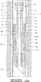
- FIG. 1 shows well 10 comprising a wellbore 12 with a casing 14 cemented therein.
- Downhole tool 16 comprises a mandrel 18 with an outer surface 20 and an inner surface 22.
- the tool in FIG. 1 may generally be referred to as a bridge plug since downhole tool 16 has an optional plug 24 pinned within mandrel 18 by radially oriented pins 26.
- Plug 24 has a seal 28 located between plug 24 and mandrel 18.
- the overall tool structure would be suited for use as and referred to simply as a packer if plug 24 were not incorporated and fluid communication were allowed through the tool.
- Other components may be connected so that the packer, without plug 24 may be used, for example, as a frac plug.
- a spacer ring 30 is mounted to mandrel 18 with a pin 32.
- a slip assembly 34 is disposed about mandrel 18 and spacer ring 30 provides an abutment which serves to axially retain slip assembly 34.
- Downhole tool 16 has two slip assemblies 34, namely a first slip assembly and second slip assembly which are shown in the drawings and are designated in the drawings as first and second slip assemblies 34a and 34b for ease of reference. The slip assemblies will anchor downhole tool 16 in well 10.
- the structure of slip assemblies 34a and 34b is identical, and only the orientation and position on downhole tool 16 are different.
- Each slip assembly 34 includes a slip ring 36 and slip wedge 38 which is pinned into place with pins 40.
- Slip ring 36 is an expandable slip ring 36 which has a retaining ring 42 disposed in grooves 44. Retaining ring 42 will retain slip ring 36 in an unset position about mandrel 18 when downhole tool 16 is lowered into the well. Slip rings 36 may be moved or radially expanded from the unset to the set position which is seen in FIG. 1 in which the first and second slip rings 36 engage casing 14 to hold downhole tool 16 in the well. Retaining rings 42 will break as slip rings 36 expand radially outwardly, but must have sufficient strength to prevent premature breakage. A large load, for example, 1200 pounds (544 kg) of force applied axially may be necessary to generate enough radial force to break retaining rings 42 when slip rings 36 are moved to the unset position.
- a large load for example, 1200 pounds (544 kg) of force applied axially may be necessary to generate enough radial force to break retaining rings 42 when slip rings 36 are moved to the unset position.
- Slip rings 36 are comprised of a drillable material and may be, for example, a molded phenolic and have an outer surface 46. Slip rings 36 may be made from other drillable materials as well such as drillable metals, composites and engineering grade plastics. The remainder of the slip assembly and other components of the tool may likewise be made from drillable materials.
- a plurality of inserts or buttons 48 are secured to slip ring 36 by adhesive or by other means and extend radially outwardly from outer surface 46.
- the buttons are comprised of material of sufficient hardness to partially penetrate or bite into the well casing and may be comprised, for example, of tungsten carbide or other materials. The buttons may be, for example, like those described in U. S. Patent 5,984,007 . In the set position as shown in FIG. 1 , buttons 48 will engage or grip casing 14 to hold tool 16 in place.
- Each slip ring 36 is preferably comprised of a plurality of slip segments 50. Slip segments 50 are shown in cross section in FIG. 2 . Slip rings 36 may include, for example, six to eight slip segments 50 that encircle mandrel 18. Slip ring 36 may include more or less than six or eight segments, and the examples herein are non-limiting.
- a packer element assembly 60 which includes at least one expandable packer element 62 is positioned between slip wedges 38. Packer shoes 64 may provide axial support to the ends of packer element assembly 60.
- Retaining rings 42 are disposed about slip rings 36, and may be received in grooves 44.
- Retaining rings 42 are each comprised of a retaining band 68, and a dampener, or spring suppressor 70.
- Retaining band 68 may be made from a metal, or may be a composite, such as a fiberglass composite retaining band. The examples provided are not limiting, and retaining band 68 may comprise any material, preferably a drillable material, that will provide adequate strength to prevent premature breakage.
- Dampener 70 may be made from rubber, for example, a nitrile rubber. Other materials that will dampen or suppress the energy, or spring effect of retaining band 68 may be used. Dampener 70 is affixed to retaining band 68 by, for example, bonding, or molding.
- Retaining band 68 may be a ring-shaped band 68, and may have a rectangular cross section with outer surface 72.
- Outer surface 72 may comprise outer circumferential surface 74, inner circumferential surface 76, and side surfaces 78 and 80.
- Dampener 70 may be affixed to any or all of surfaces 74, 76, 78 and 80, and may, if desired, completely encapsulate retaining band 68.
- downhole tool 16 is deployed in well 10 using known deployment means such as for example jointed or coiled tubing. Downhole tool 16 will be in an unset position wherein tool 16 does not engage well 10. Thus, neither slip ring 36, nor packer element assembly 60 will engage casing 14 in the unset position. In the unset position, spacer ring 30, both of slip rings 36a and 36b and slip wedges 38a and 38b are all in an initial position about mandrel 18 and are positioned radially inwardly from the set position shown in FIG. 1 . When downhole tool 16 reaches a desired location in the well, each of slip rings 36a and 36b are moved radially outwardly to the set position shown in FIG. 1 , and tool 16 may be left in well 10. Downhole tool 16 separates well 10 into upper well portion 10a and lower portion 10b. The upper and lower portions 10a and 10b are isolated from one another by well tool 16 which in the embodiment shown is a bridge plug.
- well tool 16 which in the embodiment shown is a bridge plug.
- Retaining rings 42 will retain slip rings 36 in place about mandrel 18 in the unset position prior to being moved to the set position in FIG. 1 .
- Retaining rings 42 will break as slip rings 36a and 36b move radially outwardly to the set position. If the retaining rings break prematurely, the slip rings 36 may move outwardly and can cause the tool to hang up in the well. Increasing the strength of the retaining rings may prevent premature breakage, but will also increase the energy released and the spring effect upon breakage.
- the retaining ring 42 disclosed herein may be designed to require as much as 3000 pounds (1361 kg) or more applied axially to generate the outward radial force necessary to break retaining ring 42.
- Retaining rings 42 will stay in groove 44, since the dampener 70 reduces the spring effect experienced by retaining rings 42 designed to break at high load levels. Dampener 70 prevents retaining ring 42 from moving out of groove 44 and becoming trapped between slip ring 36, or other tool component, and well 10. Retaining rings 42 have been shown to require as much as 4500 pounds (2041 kg) of applied axial force to break, and the spring effect reduced sufficiently to prevent retaining rings 42 from moving out of grooves 44.
- dampener 70 dampen, or suppress the spring effect, so that when retaining rings 42 break, they will stay in grooves 44.
Landscapes
- Life Sciences & Earth Sciences (AREA)
- Engineering & Computer Science (AREA)
- Geology (AREA)
- Mining & Mineral Resources (AREA)
- Physics & Mathematics (AREA)
- Environmental & Geological Engineering (AREA)
- Fluid Mechanics (AREA)
- General Life Sciences & Earth Sciences (AREA)
- Geochemistry & Mineralogy (AREA)
- Earth Drilling (AREA)
Claims (21)
- Outil de fond de trou (16) pour une utilisation dans un puits (10) comprenant :un mandrin (18) ;une bague collectrice (36) placée autour du mandrin (18) et déplaçable à partir d'une position inactive vers une position active, dans lequel dans la position active la bague collectrice entre en prise par serrage avec le puits (10) ; etune bague de retenue (42) pour maintenir la bague collectrice (36) dans la position inactive, la bague de retenue (42) comprenant une bande de retenue (68) et un amortisseur ou un suppresseur de ressort (70) fixé à la bande de retenue, dans lequel la bande de retenue (68) est composée d'un premier matériau et l'amortisseur ou le suppresseur (70) est composé d'un second matériau ; caractérisé en ce que,l'amortisseur ou le suppresseur de ressort (70) adhère à la surface externe de la bande de retenue (68) par liaison.
- Outil de fond de trou selon la revendication 1, dans lequel le premier matériau est un composé de fibre de verre et le second matériau et le caoutchouc.
- Outil de fond de trou selon la revendication 1, dans lequel l'amortisseur (70) encapsule complètement la bande de retenue (68).
- Outil de fond de trou selon la revendication 1, dans lequel l'amortisseur (70) circonscrit la bande de retenue (68) .
- Outil de fond de trou selon la revendication 1, comprenant également au moins un élément de garniture (60, 62) placé autour du mandrin (18) et une première et une seconde bagues collectrices (36a, 36b), dans lequel une bague de retenue (42) maintient chacune de la première et de la seconde bagues collectrices (36a, 36b) dans la position inactive, et dans lequel les bagues de retenue (42) se rompent lors de l'application d'une force radiale vers l'extérieur appliquée lorsque les bagues collectrices (36a, 36b) se déplacent de la position inactive vers la position active.
- Outil de fond de puits selon la revendication 1, comprenant également :une garniture expansible (60, 62) placée autour du mandrin (18) ;une première bague collectrice (36a) placée autour du mandrin (18) et déplaçable d'une position inactive vers une position active pour entrer en prise par serrage avec le tubage, la première bague collectrice (36a) étant localisée au-dessus de l'élément de garniture (62) ;une première bague de retenue (42) positionnée dans une rainure (44) dans la première bague collectrice ;une seconde bague collectrice (36b) placée autour du mandrin (18) et déplaçable d'une position inactive vers une position active pour entrer en prise par serrage avec le tubage, la seconde bague collectrice (36b) étant localisée en-dessous de l'élément de garniture (60, 62) ; etune seconde bague de retenue (42) positionnée dans une rainure (44) dans la seconde bague collectrice (36b), dans lequel la première et la seconde bagues collectrices (36a, 36b) comprennent chacune la bande de retenue (68) avec le suppresseur de ressort (70) fixé à celle-ci pour limiter l'effet de ressort qui se produit lorsque la première et la seconde bague de retenue se cassent en raison du mouvement des bagues collectrices de la position inactive vers la position active.
- Outil de fond de trou selon la revendication 6, dans lequel les suppresseurs de ressort (70) sont composés d'un caoutchouc de nitrile, et dans lequel les bandes de retenues sont composées d'un composite.
- Outil de fond de trou selon la revendication 6, dans lequel les bandes de retenue (68) sont un composite de fibre de verre.
- Outil de fond de trou selon la revendication 6, dans lequel le suppresseur de ressort (70) circonscrit la bande de retenue (68).
- Outil de fond de trou selon la revendication 6, dans lequel le suppresseur de ressort (70) encapsule la bande de retenue (68).
- Outil de fond de trou selon la revendication 6, dans lequel la première et la seconde bagues collectrices (36a, 36b) comprennent chacune une pluralité de segments de retenue (50) avec une rainure à l'intérieur pour recevoir la première et la seconde bagues de retenue.
- Outil de fond de trou selon la revendication 1,
dans lequel la bande de retenue (68) est placée autour de la bague collectrice (36) pour empêcher la bague collectrice de s'élargir radialement vers l'extérieur de façon prématurée vers la position active ; et
le suppresseur de ressort (70) est fixé à la bande de retenue (68) pour réduire l'effet de ressort de la bande de retenue lorsqu'elle se casse en raison du mouvement de la bague collectrice (36) radialement vers l'extérieur vers la position active. - Outil de fond de trou selon la revendication 12, dans lequel le suppresseur de ressort (70) est moulé sur la bande de retenue (68).
- Outil de fond de trou selon la revendication 12, dans lequel le suppresseur de ressort (70) est le caoutchouc.
- Outil de fond de trou selon la revendication 12, dans lequel le suppresseur de ressort (70) est fixé sur la surface externe de la bande de retenue (68).
- Outil de fond de trou selon la revendication 12, dans lequel le suppresseur de ressort (70) encapsule la bande de retenue (68).
- Outil de fond de trou selon la revendication 12, dans lequel la bague collectrice (36) comprend une pluralité de segments de retenue (50), chacun avec une rainure à l'intérieur, la bande de retenue avec le suppresseur de ressort (70) fixé étant reçu dans la rainure de chaque segment de retenue.
- Outil de fond de puits selon la revendication 12, comprenant :des première et seconde bagues collectrices (36a, 36b) placées autour du mandrin (18) ; etun élément de garniture expansible (60, 62) placé autour du mandrin (18) et positionné entre la première et la seconde bagues collectrices (36a, 36b), chacune de la première et de la seconde bagues collectrices ayant une bande de retenue (68) placée autour de celles-ci, chaque bande de retenue ayant un suppresseur de ressort (70) fixé à celle-ci.
- Outil de fond de trou selon la revendication 18, dans lequel le suppresseur de ressort est un suppresseur de ressort en caoutchouc lié à la bande de retenue.
- Outil de fond de trou selon la revendication 18, le suppresseur de ressort (70) comprenant un suppresseur de ressort en caoutchouc moulé sur la bande de retenue (68).
- Outil de fond de trou selon la revendication 18, la première et la seconde bagues collectrices (36a, 36b) comprenant chacune une pluralité de segments de retenue (50) avec une rainure à l'intérieur pour recevoir les bandes de retenue.
Applications Claiming Priority (2)
| Application Number | Priority Date | Filing Date | Title |
|---|---|---|---|
| US12/217,840 US7779906B2 (en) | 2008-07-09 | 2008-07-09 | Downhole tool with multiple material retaining ring |
| PCT/GB2009/001481 WO2010004250A1 (fr) | 2008-07-09 | 2009-06-15 | Outil de fond de trou avec bague de maintien en matériaux multiples |
Publications (2)
| Publication Number | Publication Date |
|---|---|
| EP2313606A1 EP2313606A1 (fr) | 2011-04-27 |
| EP2313606B1 true EP2313606B1 (fr) | 2018-10-17 |
Family
ID=41087412
Family Applications (1)
| Application Number | Title | Priority Date | Filing Date |
|---|---|---|---|
| EP09784606.7A Not-in-force EP2313606B1 (fr) | 2008-07-09 | 2009-06-15 | Outil de fond de trou avec bague de maintien en matériaux multiples |
Country Status (5)
| Country | Link |
|---|---|
| US (1) | US7779906B2 (fr) |
| EP (1) | EP2313606B1 (fr) |
| CA (1) | CA2729922C (fr) |
| DK (1) | DK2313606T3 (fr) |
| WO (1) | WO2010004250A1 (fr) |
Families Citing this family (24)
| Publication number | Priority date | Publication date | Assignee | Title |
|---|---|---|---|---|
| US8668012B2 (en) | 2011-02-10 | 2014-03-11 | Halliburton Energy Services, Inc. | System and method for servicing a wellbore |
| US8695710B2 (en) | 2011-02-10 | 2014-04-15 | Halliburton Energy Services, Inc. | Method for individually servicing a plurality of zones of a subterranean formation |
| US8276675B2 (en) | 2009-08-11 | 2012-10-02 | Halliburton Energy Services Inc. | System and method for servicing a wellbore |
| US8668016B2 (en) | 2009-08-11 | 2014-03-11 | Halliburton Energy Services, Inc. | System and method for servicing a wellbore |
| US8272443B2 (en) | 2009-11-12 | 2012-09-25 | Halliburton Energy Services Inc. | Downhole progressive pressurization actuated tool and method of using the same |
| US8991485B2 (en) | 2010-11-23 | 2015-03-31 | Wireline Solutions, Llc | Non-metallic slip assembly and related methods |
| GB2485790A (en) * | 2010-11-23 | 2012-05-30 | Avalon Sciences Ltd | Retaining ring |
| US8893811B2 (en) | 2011-06-08 | 2014-11-25 | Halliburton Energy Services, Inc. | Responsively activated wellbore stimulation assemblies and methods of using the same |
| US8899334B2 (en) | 2011-08-23 | 2014-12-02 | Halliburton Energy Services, Inc. | System and method for servicing a wellbore |
| US8662178B2 (en) | 2011-09-29 | 2014-03-04 | Halliburton Energy Services, Inc. | Responsively activated wellbore stimulation assemblies and methods of using the same |
| US8887818B1 (en) | 2011-11-02 | 2014-11-18 | Diamondback Industries, Inc. | Composite frac plug |
| US8991509B2 (en) | 2012-04-30 | 2015-03-31 | Halliburton Energy Services, Inc. | Delayed activation activatable stimulation assembly |
| US9784070B2 (en) | 2012-06-29 | 2017-10-10 | Halliburton Energy Services, Inc. | System and method for servicing a wellbore |
| US9157288B2 (en) | 2012-07-19 | 2015-10-13 | General Plastics & Composites, L.P. | Downhole tool system and method related thereto |
| US9470060B2 (en) * | 2012-09-06 | 2016-10-18 | Weatherford Technology Holdings, Llc | Standoff device for downhole tools using slip elements |
| US9725981B2 (en) | 2012-10-01 | 2017-08-08 | Weatherford Technology Holdings, Llc | Non-metallic slips having inserts oriented normal to cone face |
| US9677356B2 (en) | 2012-10-01 | 2017-06-13 | Weatherford Technology Holdings, Llc | Insert units for non-metallic slips oriented normal to cone face |
| US9416617B2 (en) | 2013-02-12 | 2016-08-16 | Weatherford Technology Holdings, Llc | Downhole tool having slip inserts composed of different materials |
| US11193347B2 (en) * | 2018-11-07 | 2021-12-07 | Petroquip Energy Services, Llp | Slip insert for tool retention |
| US11118434B2 (en) | 2019-07-08 | 2021-09-14 | Halliburton Energy Services, Inc. | Expandable hanger with anchor feature |
| US11035197B2 (en) * | 2019-09-24 | 2021-06-15 | Exacta-Frac Energy Services, Inc. | Anchoring extrusion limiter for non-retrievable packers and composite frac plug incorporating same |
| CN110984901B (zh) * | 2019-11-06 | 2021-10-15 | 大庆油田有限责任公司 | 一种压裂后快速下泵完井防喷封隔器 |
| US11230903B2 (en) | 2020-02-05 | 2022-01-25 | Weatherford Technology Holdings, Llc | Downhole tool having low density slip inserts |
| CN117386315B (zh) * | 2023-10-25 | 2025-01-28 | 四川中宏瑞石油机械工程有限公司 | 一种捞磨一体装置及使用方法 |
Family Cites Families (12)
| Publication number | Priority date | Publication date | Assignee | Title |
|---|---|---|---|---|
| US5271468A (en) * | 1990-04-26 | 1993-12-21 | Halliburton Company | Downhole tool apparatus with non-metallic components and methods of drilling thereof |
| US5224540A (en) * | 1990-04-26 | 1993-07-06 | Halliburton Company | Downhole tool apparatus with non-metallic components and methods of drilling thereof |
| US5540279A (en) * | 1995-05-16 | 1996-07-30 | Halliburton Company | Downhole tool apparatus with non-metallic packer element retaining shoes |
| US5701959A (en) * | 1996-03-29 | 1997-12-30 | Halliburton Company | Downhole tool apparatus and method of limiting packer element extrusion |
| US5839515A (en) * | 1997-07-07 | 1998-11-24 | Halliburton Energy Services, Inc. | Slip retaining system for downhole tools |
| US5984007A (en) | 1998-01-09 | 1999-11-16 | Halliburton Energy Services, Inc. | Chip resistant buttons for downhole tools having slip elements |
| US6167963B1 (en) * | 1998-05-08 | 2001-01-02 | Baker Hughes Incorporated | Removable non-metallic bridge plug or packer |
| US6695057B2 (en) * | 2001-05-15 | 2004-02-24 | Weatherford/Lamb, Inc. | Fracturing port collar for wellbore pack-off system, and method for using same |
| US6354372B1 (en) * | 2000-01-13 | 2002-03-12 | Carisella & Cook Ventures | Subterranean well tool and slip assembly |
| US6578633B2 (en) * | 2000-06-30 | 2003-06-17 | Bj Services Company | Drillable bridge plug |
| US6394180B1 (en) | 2000-07-12 | 2002-05-28 | Halliburton Energy Service,S Inc. | Frac plug with caged ball |
| US7048066B2 (en) * | 2002-10-09 | 2006-05-23 | Halliburton Energy Services, Inc. | Downhole sealing tools and method of use |
-
2008
- 2008-07-09 US US12/217,840 patent/US7779906B2/en active Active
-
2009
- 2009-06-15 EP EP09784606.7A patent/EP2313606B1/fr not_active Not-in-force
- 2009-06-15 WO PCT/GB2009/001481 patent/WO2010004250A1/fr not_active Ceased
- 2009-06-15 CA CA2729922A patent/CA2729922C/fr not_active Expired - Fee Related
- 2009-06-15 DK DK09784606.7T patent/DK2313606T3/en active
Non-Patent Citations (1)
| Title |
|---|
| None * |
Also Published As
| Publication number | Publication date |
|---|---|
| WO2010004250A1 (fr) | 2010-01-14 |
| CA2729922A1 (fr) | 2010-01-14 |
| US20100006280A1 (en) | 2010-01-14 |
| CA2729922C (fr) | 2013-04-30 |
| DK2313606T3 (en) | 2019-01-28 |
| EP2313606A1 (fr) | 2011-04-27 |
| US7779906B2 (en) | 2010-08-24 |
Similar Documents
| Publication | Publication Date | Title |
|---|---|---|
| EP2313606B1 (fr) | Outil de fond de trou avec bague de maintien en matériaux multiples | |
| EP2221447B1 (fr) | Segments de retenue pour outil de fonds de puits | |
| CA2808138C (fr) | Coin de retenue forable pourvu de bosses et d'elements de retenue en fonte | |
| US20090038790A1 (en) | Downhole tool with slip elements having a friction surface | |
| US6695051B2 (en) | Expandable retaining shoe | |
| US6695050B2 (en) | Expandable retaining shoe | |
| EP1172521B1 (fr) | Garniture d'étanchéité de puits avec clapet à bille captive | |
| CA2924287C (fr) | Outil de fond de trou recuperable | |
| EP0743422A2 (fr) | Ensemble d'étanchéité pour fond de trou | |
| US20140305627A1 (en) | Anti-wear device for composite packers and plugs | |
| WO2014149146A1 (fr) | Coin de retenue apte à être foré | |
| US20120255723A1 (en) | Drillable slip with non-continuous outer diameter | |
| US20190218873A1 (en) | Ceramic insert into a composite slip segment | |
| US20160298403A1 (en) | Slip segment inserts for a downhole tool | |
| WO2013009438A2 (fr) | Configurations de sabot de retenue couvert destiné à être utilisé dans un outil de fond de trou | |
| EP1286019B1 (fr) | Sabot de retenue expansible |
Legal Events
| Date | Code | Title | Description |
|---|---|---|---|
| PUAI | Public reference made under article 153(3) epc to a published international application that has entered the european phase |
Free format text: ORIGINAL CODE: 0009012 |
|
| 17P | Request for examination filed |
Effective date: 20110125 |
|
| AK | Designated contracting states |
Kind code of ref document: A1 Designated state(s): AT BE BG CH CY CZ DE DK EE ES FI FR GB GR HR HU IE IS IT LI LT LU LV MC MK MT NL NO PL PT RO SE SI SK TR |
|
| AX | Request for extension of the european patent |
Extension state: AL BA RS |
|
| DAX | Request for extension of the european patent (deleted) | ||
| STAA | Information on the status of an ep patent application or granted ep patent |
Free format text: STATUS: EXAMINATION IS IN PROGRESS |
|
| 17Q | First examination report despatched |
Effective date: 20170516 |
|
| GRAP | Despatch of communication of intention to grant a patent |
Free format text: ORIGINAL CODE: EPIDOSNIGR1 |
|
| STAA | Information on the status of an ep patent application or granted ep patent |
Free format text: STATUS: GRANT OF PATENT IS INTENDED |
|
| INTG | Intention to grant announced |
Effective date: 20180518 |
|
| RIN1 | Information on inventor provided before grant (corrected) |
Inventor name: PORTER, JESSE C. Inventor name: BARLOW, JOEL |
|
| GRAS | Grant fee paid |
Free format text: ORIGINAL CODE: EPIDOSNIGR3 |
|
| GRAA | (expected) grant |
Free format text: ORIGINAL CODE: 0009210 |
|
| STAA | Information on the status of an ep patent application or granted ep patent |
Free format text: STATUS: THE PATENT HAS BEEN GRANTED |
|
| RAP1 | Party data changed (applicant data changed or rights of an application transferred) |
Owner name: HALLIBURTON ENERGY SERVICES, INC. |
|
| AK | Designated contracting states |
Kind code of ref document: B1 Designated state(s): AT BE BG CH CY CZ DE DK EE ES FI FR GB GR HR HU IE IS IT LI LT LU LV MC MK MT NL NO PL PT RO SE SI SK TR |
|
| REG | Reference to a national code |
Ref country code: GB Ref legal event code: FG4D |
|
| REG | Reference to a national code |
Ref country code: CH Ref legal event code: EP |
|
| REG | Reference to a national code |
Ref country code: IE Ref legal event code: FG4D |
|
| REG | Reference to a national code |
Ref country code: DE Ref legal event code: R096 Ref document number: 602009055136 Country of ref document: DE Ref country code: AT Ref legal event code: REF Ref document number: 1054254 Country of ref document: AT Kind code of ref document: T Effective date: 20181115 |
|
| REG | Reference to a national code |
Ref country code: RO Ref legal event code: EPE |
|
| REG | Reference to a national code |
Ref country code: NO Ref legal event code: T2 Effective date: 20181017 Ref country code: DK Ref legal event code: T3 Effective date: 20190123 |
|
| REG | Reference to a national code |
Ref country code: NL Ref legal event code: MP Effective date: 20181017 |
|
| REG | Reference to a national code |
Ref country code: LT Ref legal event code: MG4D |
|
| REG | Reference to a national code |
Ref country code: AT Ref legal event code: MK05 Ref document number: 1054254 Country of ref document: AT Kind code of ref document: T Effective date: 20181017 |
|
| PG25 | Lapsed in a contracting state [announced via postgrant information from national office to epo] |
Ref country code: NL Free format text: LAPSE BECAUSE OF FAILURE TO SUBMIT A TRANSLATION OF THE DESCRIPTION OR TO PAY THE FEE WITHIN THE PRESCRIBED TIME-LIMIT Effective date: 20181017 |
|
| PG25 | Lapsed in a contracting state [announced via postgrant information from national office to epo] |
Ref country code: LV Free format text: LAPSE BECAUSE OF FAILURE TO SUBMIT A TRANSLATION OF THE DESCRIPTION OR TO PAY THE FEE WITHIN THE PRESCRIBED TIME-LIMIT Effective date: 20181017 Ref country code: AT Free format text: LAPSE BECAUSE OF FAILURE TO SUBMIT A TRANSLATION OF THE DESCRIPTION OR TO PAY THE FEE WITHIN THE PRESCRIBED TIME-LIMIT Effective date: 20181017 Ref country code: FI Free format text: LAPSE BECAUSE OF FAILURE TO SUBMIT A TRANSLATION OF THE DESCRIPTION OR TO PAY THE FEE WITHIN THE PRESCRIBED TIME-LIMIT Effective date: 20181017 Ref country code: IS Free format text: LAPSE BECAUSE OF FAILURE TO SUBMIT A TRANSLATION OF THE DESCRIPTION OR TO PAY THE FEE WITHIN THE PRESCRIBED TIME-LIMIT Effective date: 20190217 Ref country code: LT Free format text: LAPSE BECAUSE OF FAILURE TO SUBMIT A TRANSLATION OF THE DESCRIPTION OR TO PAY THE FEE WITHIN THE PRESCRIBED TIME-LIMIT Effective date: 20181017 Ref country code: HR Free format text: LAPSE BECAUSE OF FAILURE TO SUBMIT A TRANSLATION OF THE DESCRIPTION OR TO PAY THE FEE WITHIN THE PRESCRIBED TIME-LIMIT Effective date: 20181017 Ref country code: PL Free format text: LAPSE BECAUSE OF FAILURE TO SUBMIT A TRANSLATION OF THE DESCRIPTION OR TO PAY THE FEE WITHIN THE PRESCRIBED TIME-LIMIT Effective date: 20181017 Ref country code: BG Free format text: LAPSE BECAUSE OF FAILURE TO SUBMIT A TRANSLATION OF THE DESCRIPTION OR TO PAY THE FEE WITHIN THE PRESCRIBED TIME-LIMIT Effective date: 20190117 Ref country code: ES Free format text: LAPSE BECAUSE OF FAILURE TO SUBMIT A TRANSLATION OF THE DESCRIPTION OR TO PAY THE FEE WITHIN THE PRESCRIBED TIME-LIMIT Effective date: 20181017 |
|
| PG25 | Lapsed in a contracting state [announced via postgrant information from national office to epo] |
Ref country code: GR Free format text: LAPSE BECAUSE OF FAILURE TO SUBMIT A TRANSLATION OF THE DESCRIPTION OR TO PAY THE FEE WITHIN THE PRESCRIBED TIME-LIMIT Effective date: 20190118 Ref country code: PT Free format text: LAPSE BECAUSE OF FAILURE TO SUBMIT A TRANSLATION OF THE DESCRIPTION OR TO PAY THE FEE WITHIN THE PRESCRIBED TIME-LIMIT Effective date: 20190217 Ref country code: SE Free format text: LAPSE BECAUSE OF FAILURE TO SUBMIT A TRANSLATION OF THE DESCRIPTION OR TO PAY THE FEE WITHIN THE PRESCRIBED TIME-LIMIT Effective date: 20181017 |
|
| REG | Reference to a national code |
Ref country code: DE Ref legal event code: R097 Ref document number: 602009055136 Country of ref document: DE |
|
| PG25 | Lapsed in a contracting state [announced via postgrant information from national office to epo] |
Ref country code: IT Free format text: LAPSE BECAUSE OF FAILURE TO SUBMIT A TRANSLATION OF THE DESCRIPTION OR TO PAY THE FEE WITHIN THE PRESCRIBED TIME-LIMIT Effective date: 20181017 Ref country code: CZ Free format text: LAPSE BECAUSE OF FAILURE TO SUBMIT A TRANSLATION OF THE DESCRIPTION OR TO PAY THE FEE WITHIN THE PRESCRIBED TIME-LIMIT Effective date: 20181017 |
|
| PGFP | Annual fee paid to national office [announced via postgrant information from national office to epo] |
Ref country code: BE Payment date: 20190619 Year of fee payment: 12 |
|
| PLBE | No opposition filed within time limit |
Free format text: ORIGINAL CODE: 0009261 |
|
| STAA | Information on the status of an ep patent application or granted ep patent |
Free format text: STATUS: NO OPPOSITION FILED WITHIN TIME LIMIT |
|
| PG25 | Lapsed in a contracting state [announced via postgrant information from national office to epo] |
Ref country code: SK Free format text: LAPSE BECAUSE OF FAILURE TO SUBMIT A TRANSLATION OF THE DESCRIPTION OR TO PAY THE FEE WITHIN THE PRESCRIBED TIME-LIMIT Effective date: 20181017 Ref country code: EE Free format text: LAPSE BECAUSE OF FAILURE TO SUBMIT A TRANSLATION OF THE DESCRIPTION OR TO PAY THE FEE WITHIN THE PRESCRIBED TIME-LIMIT Effective date: 20181017 |
|
| PGFP | Annual fee paid to national office [announced via postgrant information from national office to epo] |
Ref country code: RO Payment date: 20190603 Year of fee payment: 11 |
|
| 26N | No opposition filed |
Effective date: 20190718 |
|
| PG25 | Lapsed in a contracting state [announced via postgrant information from national office to epo] |
Ref country code: SI Free format text: LAPSE BECAUSE OF FAILURE TO SUBMIT A TRANSLATION OF THE DESCRIPTION OR TO PAY THE FEE WITHIN THE PRESCRIBED TIME-LIMIT Effective date: 20181017 |
|
| REG | Reference to a national code |
Ref country code: DE Ref legal event code: R119 Ref document number: 602009055136 Country of ref document: DE |
|
| PG25 | Lapsed in a contracting state [announced via postgrant information from national office to epo] |
Ref country code: MC Free format text: LAPSE BECAUSE OF FAILURE TO SUBMIT A TRANSLATION OF THE DESCRIPTION OR TO PAY THE FEE WITHIN THE PRESCRIBED TIME-LIMIT Effective date: 20181017 |
|
| REG | Reference to a national code |
Ref country code: CH Ref legal event code: PL |
|
| REG | Reference to a national code |
Ref country code: BE Ref legal event code: MM Effective date: 20190630 |
|
| PG25 | Lapsed in a contracting state [announced via postgrant information from national office to epo] |
Ref country code: TR Free format text: LAPSE BECAUSE OF FAILURE TO SUBMIT A TRANSLATION OF THE DESCRIPTION OR TO PAY THE FEE WITHIN THE PRESCRIBED TIME-LIMIT Effective date: 20181017 |
|
| PG25 | Lapsed in a contracting state [announced via postgrant information from national office to epo] |
Ref country code: DE Free format text: LAPSE BECAUSE OF NON-PAYMENT OF DUE FEES Effective date: 20200101 Ref country code: IE Free format text: LAPSE BECAUSE OF NON-PAYMENT OF DUE FEES Effective date: 20190615 |
|
| PG25 | Lapsed in a contracting state [announced via postgrant information from national office to epo] |
Ref country code: LU Free format text: LAPSE BECAUSE OF NON-PAYMENT OF DUE FEES Effective date: 20190615 Ref country code: BE Free format text: LAPSE BECAUSE OF NON-PAYMENT OF DUE FEES Effective date: 20190630 Ref country code: LI Free format text: LAPSE BECAUSE OF NON-PAYMENT OF DUE FEES Effective date: 20190630 Ref country code: CH Free format text: LAPSE BECAUSE OF NON-PAYMENT OF DUE FEES Effective date: 20190630 |
|
| PG25 | Lapsed in a contracting state [announced via postgrant information from national office to epo] |
Ref country code: FR Free format text: LAPSE BECAUSE OF NON-PAYMENT OF DUE FEES Effective date: 20190630 |
|
| PGFP | Annual fee paid to national office [announced via postgrant information from national office to epo] |
Ref country code: NO Payment date: 20200527 Year of fee payment: 12 |
|
| PGFP | Annual fee paid to national office [announced via postgrant information from national office to epo] |
Ref country code: GB Payment date: 20200527 Year of fee payment: 12 |
|
| REG | Reference to a national code |
Ref country code: DK Ref legal event code: EBP Effective date: 20200630 |
|
| PG25 | Lapsed in a contracting state [announced via postgrant information from national office to epo] |
Ref country code: RO Free format text: LAPSE BECAUSE OF NON-PAYMENT OF DUE FEES Effective date: 20200615 |
|
| PG25 | Lapsed in a contracting state [announced via postgrant information from national office to epo] |
Ref country code: CY Free format text: LAPSE BECAUSE OF FAILURE TO SUBMIT A TRANSLATION OF THE DESCRIPTION OR TO PAY THE FEE WITHIN THE PRESCRIBED TIME-LIMIT Effective date: 20181017 |
|
| PG25 | Lapsed in a contracting state [announced via postgrant information from national office to epo] |
Ref country code: HU Free format text: LAPSE BECAUSE OF FAILURE TO SUBMIT A TRANSLATION OF THE DESCRIPTION OR TO PAY THE FEE WITHIN THE PRESCRIBED TIME-LIMIT; INVALID AB INITIO Effective date: 20090615 Ref country code: MT Free format text: LAPSE BECAUSE OF FAILURE TO SUBMIT A TRANSLATION OF THE DESCRIPTION OR TO PAY THE FEE WITHIN THE PRESCRIBED TIME-LIMIT Effective date: 20181017 |
|
| PG25 | Lapsed in a contracting state [announced via postgrant information from national office to epo] |
Ref country code: DK Free format text: LAPSE BECAUSE OF NON-PAYMENT OF DUE FEES Effective date: 20200630 |
|
| REG | Reference to a national code |
Ref country code: NO Ref legal event code: MMEP |
|
| GBPC | Gb: european patent ceased through non-payment of renewal fee |
Effective date: 20210615 |
|
| PG25 | Lapsed in a contracting state [announced via postgrant information from national office to epo] |
Ref country code: GB Free format text: LAPSE BECAUSE OF NON-PAYMENT OF DUE FEES Effective date: 20210615 |
|
| PG25 | Lapsed in a contracting state [announced via postgrant information from national office to epo] |
Ref country code: NO Free format text: LAPSE BECAUSE OF NON-PAYMENT OF DUE FEES Effective date: 20210630 |
|
| PG25 | Lapsed in a contracting state [announced via postgrant information from national office to epo] |
Ref country code: MK Free format text: LAPSE BECAUSE OF FAILURE TO SUBMIT A TRANSLATION OF THE DESCRIPTION OR TO PAY THE FEE WITHIN THE PRESCRIBED TIME-LIMIT Effective date: 20181017 |