EP2313768B1 - Détermination des rayons hydrodynamique et/ou du contenu de composants d'un mélange par analyse de la dispersion taylor du mélange dans un tube capillaire - Google Patents
Détermination des rayons hydrodynamique et/ou du contenu de composants d'un mélange par analyse de la dispersion taylor du mélange dans un tube capillaire Download PDFInfo
- Publication number
- EP2313768B1 EP2313768B1 EP09800018.5A EP09800018A EP2313768B1 EP 2313768 B1 EP2313768 B1 EP 2313768B1 EP 09800018 A EP09800018 A EP 09800018A EP 2313768 B1 EP2313768 B1 EP 2313768B1
- Authority
- EP
- European Patent Office
- Prior art keywords
- species
- mixture
- capillary tube
- signal
- taylor
- Prior art date
- Legal status (The legal status is an assumption and is not a legal conclusion. Google has not performed a legal analysis and makes no representation as to the accuracy of the status listed.)
- Not-in-force
Links
- 239000000203 mixture Substances 0.000 title claims description 108
- 238000004458 analytical method Methods 0.000 title claims description 43
- 239000006185 dispersion Substances 0.000 title claims description 34
- 239000000470 constituent Substances 0.000 title description 9
- 238000000034 method Methods 0.000 claims description 86
- 229920000642 polymer Polymers 0.000 claims description 56
- 239000000178 monomer Substances 0.000 claims description 45
- 238000001514 detection method Methods 0.000 claims description 38
- 238000002347 injection Methods 0.000 claims description 27
- 239000007924 injection Substances 0.000 claims description 27
- 238000006116 polymerization reaction Methods 0.000 claims description 25
- 238000006243 chemical reaction Methods 0.000 claims description 18
- 230000004044 response Effects 0.000 claims description 17
- 238000002474 experimental method Methods 0.000 claims description 16
- 239000007788 liquid Substances 0.000 claims description 16
- FAPWRFPIFSIZLT-UHFFFAOYSA-M Sodium chloride Chemical compound [Na+].[Cl-] FAPWRFPIFSIZLT-UHFFFAOYSA-M 0.000 claims description 13
- 238000010828 elution Methods 0.000 claims description 12
- 229920002521 macromolecule Polymers 0.000 claims description 9
- 230000003287 optical effect Effects 0.000 claims description 9
- 229920002401 polyacrylamide Polymers 0.000 claims description 9
- 150000001875 compounds Chemical class 0.000 claims description 7
- 239000002245 particle Substances 0.000 claims description 7
- -1 polysiloxanes Polymers 0.000 claims description 7
- 230000003993 interaction Effects 0.000 claims description 6
- 239000011780 sodium chloride Substances 0.000 claims description 6
- 230000002706 hydrostatic effect Effects 0.000 claims description 5
- 239000004094 surface-active agent Substances 0.000 claims description 5
- 150000003839 salts Chemical class 0.000 claims description 4
- 239000004372 Polyvinyl alcohol Substances 0.000 claims description 3
- 238000002835 absorbance Methods 0.000 claims description 3
- 239000001913 cellulose Chemical class 0.000 claims description 3
- 229920002678 cellulose Chemical class 0.000 claims description 3
- 239000004205 dimethyl polysiloxane Substances 0.000 claims description 3
- 229920000435 poly(dimethylsiloxane) Polymers 0.000 claims description 3
- 229920000867 polyelectrolyte Polymers 0.000 claims description 3
- 229920001296 polysiloxane Polymers 0.000 claims description 3
- 229920002451 polyvinyl alcohol Polymers 0.000 claims description 3
- 238000012545 processing Methods 0.000 claims description 3
- 125000000129 anionic group Chemical group 0.000 claims description 2
- 125000002091 cationic group Chemical group 0.000 claims description 2
- BTBUEUYNUDRHOZ-UHFFFAOYSA-N Borate Chemical compound [O-]B([O-])[O-] BTBUEUYNUDRHOZ-UHFFFAOYSA-N 0.000 claims 1
- 229910019142 PO4 Inorganic materials 0.000 claims 1
- NBIIXXVUZAFLBC-UHFFFAOYSA-K phosphate Chemical compound [O-]P([O-])([O-])=O NBIIXXVUZAFLBC-UHFFFAOYSA-K 0.000 claims 1
- 239000010452 phosphate Substances 0.000 claims 1
- 241000894007 species Species 0.000 description 114
- 238000009826 distribution Methods 0.000 description 23
- 238000009792 diffusion process Methods 0.000 description 21
- 239000000523 sample Substances 0.000 description 19
- LYCAIKOWRPUZTN-UHFFFAOYSA-N Ethylene glycol Chemical compound OCCO LYCAIKOWRPUZTN-UHFFFAOYSA-N 0.000 description 14
- 230000008569 process Effects 0.000 description 11
- HRPVXLWXLXDGHG-UHFFFAOYSA-N Acrylamide Chemical compound NC(=O)C=C HRPVXLWXLXDGHG-UHFFFAOYSA-N 0.000 description 9
- 108090000623 proteins and genes Proteins 0.000 description 8
- 102000004169 proteins and genes Human genes 0.000 description 8
- 239000000243 solution Substances 0.000 description 6
- 238000005259 measurement Methods 0.000 description 5
- 230000035484 reaction time Effects 0.000 description 5
- 239000002904 solvent Substances 0.000 description 5
- 239000007864 aqueous solution Substances 0.000 description 4
- 238000000149 argon plasma sintering Methods 0.000 description 4
- 238000004364 calculation method Methods 0.000 description 4
- 238000012937 correction Methods 0.000 description 4
- 239000012429 reaction media Substances 0.000 description 4
- 238000004587 chromatography analysis Methods 0.000 description 3
- 238000010790 dilution Methods 0.000 description 3
- 239000012895 dilution Substances 0.000 description 3
- 238000006073 displacement reaction Methods 0.000 description 3
- 230000005764 inhibitory process Effects 0.000 description 3
- 238000012986 modification Methods 0.000 description 3
- 230000004048 modification Effects 0.000 description 3
- 238000000926 separation method Methods 0.000 description 3
- IJGRMHOSHXDMSA-UHFFFAOYSA-N Atomic nitrogen Chemical compound N#N IJGRMHOSHXDMSA-UHFFFAOYSA-N 0.000 description 2
- 101100228469 Caenorhabditis elegans exp-1 gene Proteins 0.000 description 2
- LFQSCWFLJHTTHZ-UHFFFAOYSA-N Ethanol Chemical compound CCO LFQSCWFLJHTTHZ-UHFFFAOYSA-N 0.000 description 2
- 238000010521 absorption reaction Methods 0.000 description 2
- 238000005251 capillar electrophoresis Methods 0.000 description 2
- 230000008859 change Effects 0.000 description 2
- 238000000576 coating method Methods 0.000 description 2
- 238000010586 diagram Methods 0.000 description 2
- 230000001965 increasing effect Effects 0.000 description 2
- 230000001483 mobilizing effect Effects 0.000 description 2
- 238000012544 monitoring process Methods 0.000 description 2
- 239000002105 nanoparticle Substances 0.000 description 2
- XLYOFNOQVPJJNP-UHFFFAOYSA-N water Substances O XLYOFNOQVPJJNP-UHFFFAOYSA-N 0.000 description 2
- KWYHDKDOAIKMQN-UHFFFAOYSA-N N,N,N',N'-tetramethylethylenediamine Chemical compound CN(C)CCN(C)C KWYHDKDOAIKMQN-UHFFFAOYSA-N 0.000 description 1
- 230000033228 biological regulation Effects 0.000 description 1
- 239000008366 buffered solution Substances 0.000 description 1
- 230000003247 decreasing effect Effects 0.000 description 1
- 239000012470 diluted sample Substances 0.000 description 1
- 239000002270 dispersing agent Substances 0.000 description 1
- 238000001962 electrophoresis Methods 0.000 description 1
- 238000005516 engineering process Methods 0.000 description 1
- 229940012017 ethylenediamine Drugs 0.000 description 1
- 238000000105 evaporative light scattering detection Methods 0.000 description 1
- 238000004401 flow injection analysis Methods 0.000 description 1
- 238000001917 fluorescence detection Methods 0.000 description 1
- 238000009472 formulation Methods 0.000 description 1
- WGCNASOHLSPBMP-UHFFFAOYSA-N hydroxyacetaldehyde Natural products OCC=O WGCNASOHLSPBMP-UHFFFAOYSA-N 0.000 description 1
- 230000001939 inductive effect Effects 0.000 description 1
- 238000013383 initial experiment Methods 0.000 description 1
- 239000003999 initiator Substances 0.000 description 1
- 230000009878 intermolecular interaction Effects 0.000 description 1
- 239000004816 latex Substances 0.000 description 1
- 229920000126 latex Polymers 0.000 description 1
- 238000012886 linear function Methods 0.000 description 1
- 229910052757 nitrogen Inorganic materials 0.000 description 1
- 239000012299 nitrogen atmosphere Substances 0.000 description 1
- 238000010606 normalization Methods 0.000 description 1
- 239000003960 organic solvent Substances 0.000 description 1
- JRKICGRDRMAZLK-UHFFFAOYSA-L peroxydisulfate Chemical compound [O-]S(=O)(=O)OOS([O-])(=O)=O JRKICGRDRMAZLK-UHFFFAOYSA-L 0.000 description 1
- XNGIFLGASWRNHJ-UHFFFAOYSA-L phthalate(2-) Chemical compound [O-]C(=O)C1=CC=CC=C1C([O-])=O XNGIFLGASWRNHJ-UHFFFAOYSA-L 0.000 description 1
- 229920001467 poly(styrenesulfonates) Polymers 0.000 description 1
- 238000010526 radical polymerization reaction Methods 0.000 description 1
- 230000000306 recurrent effect Effects 0.000 description 1
- 238000001448 refractive index detection Methods 0.000 description 1
- 238000005070 sampling Methods 0.000 description 1
- 230000035945 sensitivity Effects 0.000 description 1
- 150000003384 small molecules Chemical class 0.000 description 1
- 238000001179 sorption measurement Methods 0.000 description 1
- 230000006641 stabilisation Effects 0.000 description 1
- 239000000126 substance Substances 0.000 description 1
- 238000012360 testing method Methods 0.000 description 1
- 238000000825 ultraviolet detection Methods 0.000 description 1
Images



Classifications
-
- B—PERFORMING OPERATIONS; TRANSPORTING
- B01—PHYSICAL OR CHEMICAL PROCESSES OR APPARATUS IN GENERAL
- B01J—CHEMICAL OR PHYSICAL PROCESSES, e.g. CATALYSIS OR COLLOID CHEMISTRY; THEIR RELEVANT APPARATUS
- B01J19/00—Chemical, physical or physico-chemical processes in general; Their relevant apparatus
- B01J19/0053—Details of the reactor
-
- B—PERFORMING OPERATIONS; TRANSPORTING
- B01—PHYSICAL OR CHEMICAL PROCESSES OR APPARATUS IN GENERAL
- B01J—CHEMICAL OR PHYSICAL PROCESSES, e.g. CATALYSIS OR COLLOID CHEMISTRY; THEIR RELEVANT APPARATUS
- B01J2208/00—Processes carried out in the presence of solid particles; Reactors therefor
- B01J2208/00796—Details of the reactor or of the particulate material
- B01J2208/00946—Features relating to the reactants or products
- B01J2208/00955—Sampling of the particulate material, the reactants or the products
-
- G—PHYSICS
- G01—MEASURING; TESTING
- G01N—INVESTIGATING OR ANALYSING MATERIALS BY DETERMINING THEIR CHEMICAL OR PHYSICAL PROPERTIES
- G01N15/00—Investigating characteristics of particles; Investigating permeability, pore-volume or surface-area of porous materials
- G01N15/10—Investigating individual particles
- G01N15/14—Optical investigation techniques, e.g. flow cytometry
- G01N15/1456—Optical investigation techniques, e.g. flow cytometry without spatial resolution of the texture or inner structure of the particle, e.g. processing of pulse signals
- G01N15/1459—Optical investigation techniques, e.g. flow cytometry without spatial resolution of the texture or inner structure of the particle, e.g. processing of pulse signals the analysis being performed on a sample stream
-
- G—PHYSICS
- G01—MEASURING; TESTING
- G01N—INVESTIGATING OR ANALYSING MATERIALS BY DETERMINING THEIR CHEMICAL OR PHYSICAL PROPERTIES
- G01N15/00—Investigating characteristics of particles; Investigating permeability, pore-volume or surface-area of porous materials
- G01N2015/0092—Monitoring flocculation or agglomeration
-
- G—PHYSICS
- G01—MEASURING; TESTING
- G01N—INVESTIGATING OR ANALYSING MATERIALS BY DETERMINING THEIR CHEMICAL OR PHYSICAL PROPERTIES
- G01N30/00—Investigating or analysing materials by separation into components using adsorption, absorption or similar phenomena or using ion-exchange, e.g. chromatography or field flow fractionation
- G01N30/0005—Field flow fractionation
- G01N2030/001—Field flow fractionation hydrodynamic fractionation, e.g. CHDF or HDC
-
- G—PHYSICS
- G01—MEASURING; TESTING
- G01N—INVESTIGATING OR ANALYSING MATERIALS BY DETERMINING THEIR CHEMICAL OR PHYSICAL PROPERTIES
- G01N33/00—Investigating or analysing materials by specific methods not covered by groups G01N1/00 - G01N31/00
- G01N33/44—Resins; Plastics; Rubber; Leather
- G01N33/442—Resins; Plastics
Definitions
- the instant invention relates to a method for analysing specific complex mixtures, which takes profit of the phenomenon of Taylor dispersion which takes place when species are mobilized in a capillary tube under hydrodynamic flow.
- the method of the invention which allows to easily establish both the dimensions and the contents of the constituents of the mixture, is especially suitable for analysing a polymerization medium comprising a mixture including monomers and corresponding polymers.
- the instant invention aims at providing a new analysis method which allows to obtain direct information about the content and the size of the constituent of a mixture without having to preliminarily separate the constituents of the mixture.
- the invention especially aims at providing a method suitable for directly and simply analysing a polymerization medium including monomers and corresponding polymers and allowing to easily determine both the remaining content of monomers in the medium and the size of the formed polymers.
- the instant invention provides a new method of analysis which makes use of the phenomenon of Taylor dispersion in a capillary tube.
- This new method is suitable for analysing specific mixtures, namely of the type including at least two kind of species which may be distinguished by a distinct response on a detection device.
- the invention relates to a method for analysing a mixture M according to claim 1.
- the method of the invention implements a Taylor dispersion of the species (i) and (ii) of the mixture M inside a capillary tube (step (A)) and a measurement of a signal reflecting the Taylor dispersion obtained in that way (step (B)), these steps being specifically followed by an analysis of the obtained signal (step (C)).
- the signal of step (B) is generally obtained in the form of a diagram reflecting the evolution in time of the intensity detected by the detector placed in the region of the outlet of the capillary tube.
- This diagram which is analogous to the chromatograms obtained with chromatographic methods, will be referred hereinafter as a "taylorgram", since it reflects the Taylor dispersion.
- the Taylor dispersion which is used in the method of the invention is a well known phenomenon, which occurs when a species (especially in solution or dispersion) is forced to move in a hollow tube having a small internal diameter, by inducing a hydrodynamic flow in the tube.
- the hydrodynamic flow brings about a dispersive velocity profile within the tube, generally parabolic (of the Poiseuille profile type), the molecules or particles of a species which are closest to the wall of the tube having a displacement velocity which is almost zero, this velocity increasing as these molecules or particles move closer to the axis, with a maximum velocity for those which are located at the centre of the tube.
- the hydrodynamic radius of a given species is related to the diffusion coefficient of this species, and said diffusion induces a more or less widening of the peak of the taylorgram (generally the lower the diffusion coefficient, the higher the broadening).
- This equation provides two values of the hydrodynamic radius. One of them can generally be discarded as being non-physical. If this is not the case, at least one additional analysis, performed at a different flow velocity (or mobilizing pressure) is required to solve this indetermination problem. The common value is then the correct one.
- Another technique to get rid of this corrections in a certain extent is to use a detection device having two points of measurements, whether two detectors along the capillary tube or a loop in the capillary tube effecting the mixture to pass twice in front of the same detector, l s being then the distance between the two points of detection along the capillary tube. This was described in the article by A. J. S. Chapman and D. M. Goodhall, Chromatography Today, Vol.1, June 2008, 22-24 .
- the Taylor Dispersion Analysis described hereinabove is not suitable for analysing media comprising a mixture of species.
- a direct Taylor dispersion analysis of a mixture conducted as described above leads to a global signal which reflects the global properties of the mixture, namely the average size of the whole species present in the mixture. This global information does not provide any indication on the specific properties of each of the species of the mixture, especially when the mixture contains monomers and corresponding polymers.
- taylorgrams which are obtained for most of the mixtures can actually be interpreted so as to establish respective contributions of each species which are part of the mixture. More precisely, the inventors have surprisingly evidenced that a deconvolution of the taylorgram of a mixture is possible when the mixture contains a first species of predetermined nature, known as having a monodisperse distribution (defined molecule or defined macromolecule, for example) and a second polydisperse species having a response coefficient different from the response coefficient of the first species on a detection device.
- a first species of predetermined nature known as having a monodisperse distribution (defined molecule or defined macromolecule, for example) and a second polydisperse species having a response coefficient different from the response coefficient of the first species on a detection device.
- response coefficient of a species on a given detection device denotes the proportionality coefficient between the detector signal and the concentration of the species, this concentration being appropriately defined.
- the term "detection device” herein refers to any detection device which is useful for detecting the species (i) and (ii) at the end of the capillary tube of step (A), wherein the Taylor dispersion occurs, for example a UV detection device, an refractive index detection device, a light scattering detection device, a fluorescence detection device, or a conductivity detection device (for example of the type referred to as a “contactless conductivity detector”), a viscosity detection device, a mass spectrometer, an infrared detector, a NMR detector, an evaporative light scattering detector and the like.
- a UV detection device for example a UV detection device, an refractive index detection device, a light scattering detection device, a fluorescence detection device, or a conductivity detection device (for example of the type referred to as a “contactless conductivity detector”), a viscosity detection device, a mass spectrometer, an infrared detector, a NMR detector,
- the mean hydrodynamic radius of the species (i) or (ii) is a weight mean when using a mass concentration sensitive detector, a number mean when using a molar concentration sensitive detector or a z-mean when using a light scattering detector.
- a great number of mixtures may be analysed according to the process of the invention, provided that they contain species which are sufficiently different in nature (as a matter of fact, a difference in nature generally implies that it exists at least one detector for which the response coefficients of the species will be distinct).
- a mixture analysed according to the process of the invention includes two different kinds of species, namely a monodisperse species (i) and a polydisperse species (ii).
- monodisperse species denotes a non-polymerized species (i.e. a defined molecule) or a population of polymerized macromolecules species wherein all the macromolecules have the same size.
- polydisperse species refers to a population of molecules, macromolecules, particles and/or aggregates which is not monodisperse, i.e. wherein the species have distinct sizes.
- a polydisperse species is characterized by a polydispersity index greater than 1.
- a polydisperse species as used according to the instant invention has preferably a polydispersity index greater than 1.05, more preferably greater than 1.1.
- the method of the invention is suitable for analysing mixtures including:
- the method of the invention may advantageously be carried out for analysing a mixture M which is a polymerization medium, and wherein species (i) is a monomer or a mixture of monomers and species (ii) is a polymer obtained by polymerization of said species.
- species (i) is a monomer or a mixture of monomers
- species (ii) is a polymer obtained by polymerization of said species.
- at least one of the followings parameters are determined in step (C):
- the method of the invention may besides be used for analysing other types of mixtures, such as, for example:
- the process of the invention may be carried out efficiently with extremely little quantities of the mixture to be analysed (quantities as small as 1 to 10 nL are generally injected). Furthermore, the process of the invention does not necessitate any expensive or bulky equipment.
- steps (A) and (B) of the method of the invention may be implemented in almost all known capillary electrophoresis devices with no significant technical modification of these devices, which allows implementation of these steps (A) and (B) to be envisaged without any additional cost in most of existing commercial electrophoresis devices.
- the method of the invention may be advantageously implemented both in the field of the search and on an industrial scale, especially for monitoring the evolution of reactions such as polymerization or for studying the stability of polymer / proteins formulations.
- step (C) the analysis of the taylorgram (i.e. of the signal obtained in step (B)) is performed in step (C).
- step (C) the specific contributions of species (i) and (ii) on the signal obtained in step (B) are established, which allows to determine the content and/or the mean hydrodynamic radius of species (i) and/or (ii).
- step (C) is carried out as follows:
- the method according to the first embodiment of the invention may be carried out by implementing a light scattering detection device.
- the difference of hydrodynamic radii offers the possibility of directly establishing the contributions of species (i) in the signal obtained in step (B) by a deconvolution of the signal.
- the method is carried out such that, in step (C), the respective contributions of species (i) and (ii) in the signal obtained in step (B) are established, whereby the elution profiles of species (i) and (ii) are obtained, which allows to determine the content of species (i) and/or (ii) in the mixture M, and/or the mean hydrodynamic radius of the species (i) and/or (ii).
- This second embodiment of the method is especially advantageous since it does not need any initial Taylor experiment.
- the method according to the second embodiment of the invention is suitable for analyzing any mixture containing (i) monodisperse species of a predetermined nature (such as proteins for example); and (ii) aggregates and/or particles (proteins aggregates for example).
- step (C) the respective contributions of species (i) and (ii) in the signal obtained in step (B) are established in step (C) by:
- b is a period of time large enough for the signal to vanish at t d,n - b and at t d,n + b.
- the respective contributions of species (i) and (ii) in the signal obtained in step (B) are established, in step (C), by fitting a function which is the sum of first and second Gaussian distributions onto the signal S n ( t ) , resulting in first and second fitted Gaussian distributions corresponding to the elution profiles of species (i) and (ii).
- the mixture M being a polymerization medium, and the species (i) being a monomer and the species (ii) being polymers obtained by polymerization of said species (i), the followings are determined in step (C) :
- the mixture M is diluted or dissolved in a medium identical to the carrier liquid used in the Taylor dispersion of step (A), before injecting it in the capillary.
- the internal surface of the capillary tube is non-covalently or covalently coated with a compound which limits or inhibits the interaction between the species (i) and (ii) and the inner surface of the capillary tube, said coated compound being chosen from the group consisting in PEO, cellulose derivatives, polyvinyl alcohol, polyacrylamides, polysiloxanes such as polydimethylsiloxane, anionic or cationic (mono- or double-chain) surfactants, polyelectrolyte mono or multilayer(s).
- the mixture M is introduced in the capillary tube together with a carrier liquid (a good solvent of the solute mixture).
- a carrier liquid a good solvent of the solute mixture.
- the carrier liquid generally includes a salt, for example NaCl, or a buffered solution.
- the object of the invention is also an apparatus for a Taylor experiment, comprises a detector and an analysis device, said detector comprises a capillary tube through which flows the mixture M to be analysed, injection means (6) for the injection of the mixture M into the capillary tube, and at least one set of optical means to produce a Taylor signal, and said analysis device comprising memorisation means, processing means, an I/O interface to receive from said detector said Taylor signal, and means for the implementation of the method of the invention.
- Apparatus 1 comprises a detector 2 and an analysis device 14.
- Detector 2 contains a capillary tube 6 through which flows the mixture to be analysed. At the input end of the capillary tube, detector 2 contains injection means 3 for the injection of the mixture to be analysed.
- the injection means 3 allows a unit pulse injection (i.e. a plug injection) or a unit step injection (i.e. a continuous injection of the sample) to be performed.
- the injection means allows a constant pressure injection or, in another embodiment, a constant flow injection.
- the detector 2 contains a light source S and an optical system 4 to irradiate the capillary tube 6.
- the detector 2 contains an optical sensor 10 coupled to an electronic board 12 capable of generating an electrical signal S.
- the level of signal S depends directly on the amount of light incident on sensor 10 during a period of time equal to the sampling time.
- Detector 2 is connected to an analysis device 14 through an Input/Output interface 16.
- Device 14 further comprises memorisation means, such as RAM and/or ROM 18, and processing means, such that CPU 20.
- Device 14 is also provided with means to allow an operator to interact with software running on device 14. For example, device 14 is equiped with a tactile screen 22.
- the method of treatment of the electrical signal S that will be described hereafter in details is preferably performed by a software comprising instructions memorised in ROM 18 and processed by CPU 20.
- step (A) the mixture M, as such or dissolved and/or dispersed in a proper solvent or dispersant, is injected in the capillary tube and forced to be transported in this capillary tube by the flow of a carrier liquid induced by a positive hydrodynamic and/or hydrostatic pressure difference between the inlet and the outlet of the capillary.
- the capillary tube 6 used in step (A) has advantageously an inner diameter of between 5 and 500 ⁇ m.
- the inner diameter of the capillary is advantageously less than or equal to 300 ⁇ m, preferably less than or equal to 100 ⁇ m, especially in order to prevent an excessively high level of dispersion of the peaks.
- this inner diameter it is preferable for this inner diameter to remain greater than or equal to 10 ⁇ m, in particular in order to allow adequate sensitivity of measurement and also to provide for conditions under which the plate height H is a linear function of the mobilizing velocity u.
- the inner diameter of the capillary tube used in step (A) is between 25 and 100 ⁇ m.
- capillaries which can advantageously be used to implement step (A)
- capillaries which can advantageously be used to implement step (A)
- capillaries having an inner diameter of 10 ⁇ m, 25 ⁇ m, 50 ⁇ m, 75 ⁇ m or 100 ⁇ m
- capillaries of 25, 50 and 75 ⁇ m being found to be particularly suitable in most cases.
- the length I of the capillary tube implemented in the method of the invention has to be sufficiently high so as to obtain a detection time well greater than the characteristic diffusion time (which is calculated by the ratio R 2 /4D wherein R is the internal radius of the capillary tube 6 and D is the diffusion coefficient).
- the length of the capillary tube used in the method of the invention is advantageously of at least 10 cm, preferably of at least 20 cm.
- the length of the capillary it is preferable for the length of the capillary to remain less than 100 cm, for example, less than or equal to 50 cm.
- the term "length of a capillary tube" intends to denote the effective length of the tube, namely the length from the inlet to the optical sensor 10 located in the region of the outlet of the capillary tube.
- step (A) The Taylor dispersion which is conducted in step (A) may be carried out in accordance with any method known per se, for example, in accordance with the technique described in J. Phys. Chem., 1974, 78, 2297-2301 or in Science, 1994, 266, 773-776 .
- the Taylor dispersion is brought about by establishing in step (A) a positive hydrodynamic and/or hydrostatic pressure difference between the inlet and the outlet of the capillary tube.
- step (A) of the method of the invention it is highly preferable that the linear displacement velocity u of the species (i) and (ii) in the capillary tube fulfils the following relation: 7 D R ⁇ u ⁇ ⁇ 4 Dl R 2
- the mobilisation rate has to be between 5.10 -4 and 2.10 -3 ms -1 , which corresponds to a pressure difference between the inlet and the outlet of the capillary tube of about 10 to 50 mbar (10 3 to 5.10 3 Pa).
- the hydrodynamic and/or hydrostatic pressure difference between the inlet and the outlet of the capillary in step (A) may be from 1 mbar to 1 bar (10 2 Pa to 10 5 Pa) especially for capillary tube having an internal diameter of 25 to 100 ⁇ m. Greater pressure difference up to 6 bars will be more suitable for capillary tube having an internal diameter of less than 25 ⁇ m and/or for longer capillary tubes (10 or 20 m for instance).
- step (A) it is generally preferable for the pressure difference applied during step (A) between the ends of the capillary to remain substantially constant for the entire duration of step (A), in particular in order to allow the most precise measurement possible of the hydrodynamic radius in step (C).
- the pressure varies at the most within +/- 0.5 mbar (50 Pa) of a fixed reference value.
- the value of this reference value most generally does not have to be determined in a precise manner.
- Other possibility is to perform the Taylor experiment by setting and controlling the flow rate instead of the pressure.
- the pressure difference between the two ends of the capillary may be established in accordance with any method known per se, for example, by applying excess pressure in the region of the inlet of the capillary or, conversely, by applying reduced pressure at the outlet.
- the pressure difference between the two ends of the capillary may be brought about by establishing a level difference between reservoirs of solvent or mobile phase at the inlet and at the outlet of the capillary. This embodiment is generally found to be advantageous since it allows a constant pressure difference to be established for the entire duration of step (A) without requiring any additional pressure regulation system.
- step (A) it is generally preferable to dilute or dissolve the mixture M in a medium identical to the carrier liquid used in the Taylor experiment before injecting it in the capillary tube 6.
- This pre-dilution or pre-solubilisation of the mixture M especially allows:
- the internal surface of the capillary is preferably non-covalently or covalently coated with a compound which limits or inhibits the interaction (especially adsorption) between the species (i) and (ii) and the inner surface of the capillary, said coated compound being preferably chosen from the group consisting in PEO, cellulose derivatives, polyvinyl alcohol, polyacrylamides, polysiloxanes such as polydimethylsiloxane, or surfactants (mono-chain or double chain surfactants).
- Polyelectrolyte multilayer coatings may be applied on the internal face of the capillary tube. Commercial coatings such as DB1, DB17 or DB225 are especially useful in this connection.
- the inhibition of the interactions between the capillary and the species (i) and (ii) improves the quality of the signal obtained in step (B) and hence facilitates the analysis of this signal in step (C).
- any other means allowing to limit or inhibit interactions between species (i) and (ii) may be advantageously implemented in the step (A).
- the mixture M is introduced in the capillary tube together with a carrier liquid including a salt, for example NaCl.
- the method of the invention may be conducted so as to sequentially analyse a plurality of N samples.
- a plurality of samples which each includes a mixture of at least two species and having two different response coefficients on at least one detection device, are analysed, according to steps (A) to (C) as defined in claim 1, in the same capillary tube, in a continuous way, the samples being injected successively in said capillary tube.
- steps (A) to (C) as defined in claim 1
- the instant invention provides an efficient and fast analysis method, which allows a high flow of sample.
- This embodiment of the method of the invention is, inter alia, especially suitable for a continuous study of the evolution of a polymerization.
- the signal S n ( t ) given by the sensor at the end of step (B) is the superposition of the signal S m,n ( t ) of the monomer m and the signal S p,n ( t ) of the polymer p.
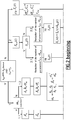
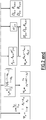
- each contribution to the global signal S n ( t ) must be separated by applying one of the following methods of treatment of the global signal S n ( t ) , as it can be seen in figure 2 .
- Coefficients k m and k p are considered constant throughout the experiment, even if the structure of a species, like the one of the polymer p, can evolve.
- the two parameters of interest are ⁇ p 2 and ⁇ n .
- the latter is connected to the areas A m,n and A p,n via equations (11) and (13).
- the measurements of the area A 0 , the height h 0 and the standard deviation ⁇ m of the signal S m, 0 ( t ) of the monomer before the polymerisation reaction allow the determination of the degree of conversion ⁇ n and of the standard deviation ⁇ p of the polymer.
- Example 1 Analysis of the Taylor dispersion of a polymerisation reaction (polyacrylamide)
- the polymerisation reaction is a radical polymerization of a acrylamide in presence of the redox couple persulfate/N,N,N',N'-tertraméthyl-ethylene-diamine as a radical initiator.
- the polymerisation has been carried out in a water/ethanol mixture (80/20 w/w) under a N 2 atmosphere at 25°C, with a initial content of acrylamide monomer in the reaction medium of 0.1 M.
- the degree of conversion of the monomer has been studied by taking samples of the reaction medium at different reaction times. For each samples, 10 microliters of the reaction medium have been taken and immediately diluted 100 times in 1 mL of a aqueous solution of NaCL (0,1 M). The resulting diluted sample has been introduced in liquid nitrogen so as to stop the polymerization reaction.
- each of the sample have been next analyzed according to the method of the invention by making use of a capillary electrophoresis device (Agilent Technologies) making use of a capillary DB1 (coated capillary commercialized by JW Scientific) having a length of 31 cm (25 cm from the inlet to the detector) and an inner diameter of 50 ⁇ m.
- the samples have been introduced hydrodynamically, by application of a pressure of 17 mbar during 10 s (which corresponds to an injected volume of about 10 nl).
- the mobilization of the solute has been made at a constant pressure of 30 mbar.
- the mobile phase used is an aqueous solution of NaCI (0.1 M).
- the presence of salt limits the interaction between the polymer and the walls of the capillary. Furthermore, it fixes the ionic force.
- a first method to separate each contribution consists in fitting a function which is the sum of two Gaussian distributions onto the global signal S n ( t ) .
- This fit involves six parameters, namely ⁇ m , ⁇ p,n , t d,m , t d,p , A m,n and A p,n .
- ⁇ m is a characteristic parameter of the monomer. It can be measured trough an initial Taylor experiment with a solution containing only the monomer.
- This method works well when the characteristic parameters of the signal of the monomer S m,n ( t ) are significantly different from those of the signal of the polymer S p,n ( t ) , i.e. when the signal of the monomer S m,n ( t ) can be "visually" separated from the signal of the polymer S p,n ( t ) .
- the signal of the monomer S m,n ( t ) is narrow and sharp whereas the signal of the polymer S p,n ( t ) is broad (i.e. when the polymer has much larger molar mases than the monomer).
- the implementation of this method in device 14 can be done by fitting a Gaussian distribution onto the global signal S n ( t ) but only inside a reduced window centered on the maximum height of the global signal.
- an iteration process can be used: in a loop of this iteration process, a fit corresponding to the monomer signal is adjusted on the global signal S n ( t ) .
- the fitted Gaussian distribution is subtracted from the global signal S n ( t ) to get the reduced signal S' n ( t ) .
- the shape of the reduced signal S' n ( t ) is tested. This test may consist in calculating the number of zeros of the derivative of the reduced signal S' n ( t ) : if the derivative has three zeros, it means that the area of the fitted Gaussian distribution is too large and that a part of the polymer signal has been considered as belonging to the monomer signal.
- the area of the Gaussian to be fitted is decreased.
- the derivative has only one zero, it means that the area of the fitted Gaussian distribution is too small and that a part of the monomer signal has not been taken into account in the monomer signal.
- the area of the Gaussian to be fitted is increased.
- Another criterion can be used such that the number of zeros of the second derivative of the resulted signal S' n ( t ) .
- l s is the length of the capillary tube from the injection point to the detector and u is the flow velocity of the carrier solvent through the tube, ⁇ is the viscosity of carrier liquid at temperature T.
- Attached Figure 5 shows the evolution of hydrodynamic radius with the reaction time, as determined by the three methods.
- Another way to use the previous described apparatus 1 is to inject the mixture to be analysed so as to make a unit step function (continuous sample injection) at the inlet end of the capillary tube, rather than a unit pulse function (plug injection) as it was generally the case in the here above methods.
- the step injection is performed under the constraint of a constant flow rate, instead of setting a constant pressure.
- the edge of the unit step function is smoothed when travelling towards the output end of the capillary tube where is positioned the optical sensor.
- the sensor outputs an electrical signal T n ( t ) .
- the fit procedure leads to the determination of five parameters, namely:
- the diffusion coefficients D for each species (i) and (ii) are calculated according to the previous described method with unit pulse injection.
- l s is the length of the capillary tube 6 from the injection point to the sensor
- ⁇ is the viscosity of carrier liquid at temperature T.
- Double detection avoids the corrections on detection time and on the variance due to finite length of the injection plug and due to the pressure ramp.
- ( l B - l A ) is the capillary length between the two detection points.
Landscapes
- Chemical & Material Sciences (AREA)
- Organic Chemistry (AREA)
- Chemical Kinetics & Catalysis (AREA)
- Investigating Or Analysing Materials By Optical Means (AREA)
Claims (11)
- Procédé pour analyser un mélange M comprenant :(i) une première espèce qui est monodispersée, et(ii) une deuxième espèce qui est polydispersée et qui a un coefficient de réponse qui est distinct du coefficient de réponse de la première espèce (i) sur au moins un dispositif de détection,ledit procédé comprenant les étapes suivantes :(A) le mélange M est injecté à l'entrée d'un tube capillaire et forcé à être transporté dans ledit tube par le flux d'un liquide porteur induit par une pression hydrostatique et/ou hydrodynamique positive entre l'entrée et la sortie du tube capillaire, en conséquence de quoi un phénomène de dispersion de Taylor de l'espèce du mélange M se produit dans le tube ;(B) par utilisation d'un détecteur capable de détecter simultanément les deux espèces (i) et (ii) et placé dans la région de la sortie du tube capillaire, un signal reflétant la dispersion de Taylor obtenue dans l'étape (A) est mesuré ;(C) le signal obtenu dans l'étape (B) est analysé par utilisation d'un dispositif d'analyse, de façon que les contributions spécifiques des espèces (i) et (ii) soient déterminées et de façon à établir ainsi au moins l'un des suivants :dans lequel les espèces (i) et (ii) ont deux rayons hydrodynamiques distincts, et l'espèce (i) est une espèce d'une nature prédéterminée, et dans lequel, dans l'étape (C), les contributions respectives des espèces (i) et (ii) dans le signal obtenu dans l'étape (B) sont établies, en conséquence de quoi les profils d'élution des espèces (i) et (ii) sont obtenus, ce qui permet la détermination de la teneur en les espèces (i) et/ou (ii) dans le mélange M, et/ou le rayon hydrodynamique moyen des espèces (i) et/ou (ii),- la teneur en les espèces (i) et/ou (ii) dans le mélange M ; et/ou- le rayon hydrodynamique moyen de l'espèce (ii) ou le rayon hydrodynamique de l'espèce (i),
en conséquence de quoi le mélange M est injecté de façon que soit effectuée une injection en étape unitaire, et les contributions respectives des espèces (i) et (ii) dans le signal Tn(t) obtenues dans l'étape (B) sont établies, dans l'étape (C), par ajustement sur le signal Tn(t) de la fonction d'ajustement suivante :


- Procédé selon la revendication 1, dans lequel le rayon hydrodynamique moyen de l'espèce (ii) est une moyenne en poids, une moyenne en nombre ou une moyenne en z.
- Procédé selon l'une quelconque des revendications 1 et 2, dans lequel le mélange M contient :- une espèce (i) constituée de molécules non polymérisées de nature prédéterminée, et- une espèce (ii) constituée de macromolécules et/ou d'agrégats et/ou de particules, et dans lequel au moins l'un des suivants est déterminé dans l'étape (C) :- la teneur en les espèces (i) et/ou (ii) dans le mélange M ; et/ou- le rayon hydrodynamique moyen de l'espèce (ii).
- Procédé selon la revendication 1, dans lequel la valeur de la variante du profil d'élution de l'espèce (ii) est utilisée pour la détermination d'un rayon hydrodynamique conformément à l'équation :

- Procédé selon la revendication 4, dans lequel la valeur de la superficie des profils d'élution des espèces (i) et (ii) est utilisée pour la détermination du degré de conversion ψ n conformément à l'équation :

- Procédé selon l'une quelconque des revendications 1 à 5, dans lequel le mélange M est un milieu de polymérisation, et dans lequel l'espèce (i) est un monomère et l'espèce (ii) est constituée de polymères obtenus par polymérisation de ladite espèce (i), et dans lequel les points suivants sont déterminés dans l'étape (C) :- la quantité de monomère (i) dans le mélange M, qui indique le degré de conversion de la polymérisation ; et/ou- le rayon hydrodynamique moyen du polymère (ii).
- Procédé selon l'une quelconque des revendications 1 à 6, dans lequel le mélange M est dilué ou dissous dans un milieu identique au liquide porteur utilisé dans la dispersion de Taylor dans l'étape (A), avant son injection dans le capillaire.
- Procédé selon l'une quelconque des revendications 1 à 7, dans lequel la surface interne du tube capillaire est revêtue, de manière covalente ou non covalente, par un composé qui limite ou inhibe l'interaction entre les espèces (i) et (ii) et la surface intérieure du tube capillaire, ledit composé déposé sous forme de revêtement étant choisi dans le groupe constitué par le PEO, les dérivés de cellulose, le poly(alcool vinylique), le polyacrylamide et ses dérivés, les polysiloxanes tels que le polydiméthylsiloxane, les tensioactifs anioniques ou cationiques (à chaîne simple ou double), les monocouches ou multicouches de polyélectrolytes.
- Procédé selon l'une quelconque des revendications 1 à 8, dans lequel le mélange M est introduit dans le tube capillaire conjointement avec un liquide porteur contenant un sel, par exemple NaCI, ou un tampon tel qu'un phosphate ou borate.
- Procédé selon l'une quelconque des revendications 1 à 9, dans lequel une pluralité d'échantillons, qui contiennent chacun un mélange d'au moins deux espèces et ont deux coefficients de réponse différents sur au moins un dispositif de détection, sont analysés conformément aux étapes (A) à (C) telles que définies dans la revendication 1 dans un même tube capillaire, de manière séquentielle, les échantillons étant injectés successivement dans ledit tube capillaire.
- Dispositif (1) 1 pour une expérience de Taylor, comprenant un détecteur (2) et un dispositif d'analyse (14), ledit détecteur comprenant un tube capillaire (6) dans lequel s'écoule le mélange M devant être analysé, des moyens d'injection (6) pour l'injection du mélange M dans le tube capillaire, et au moins un jeu de moyens optiques (4, 5, 10, 12) pour produire un signal de Taylor, ledit dispositif d'analyse comprenant des moyens de mémorisation (18), des moyens de traitement (20) et une interface d'entrée/sortie (16) pour recevoir ledit signal de Taylor à partir dudit détecteur, caractérisé en ce que ledit dispositif d'analyse (14) comprend des moyens pour la mise en oeuvre d'un procédé d'analyse selon l'une quelconque des revendications 1 à 10.
Priority Applications (1)
| Application Number | Priority Date | Filing Date | Title |
|---|---|---|---|
| EP09800018.5A EP2313768B1 (fr) | 2008-07-21 | 2009-03-13 | Détermination des rayons hydrodynamique et/ou du contenu de composants d'un mélange par analyse de la dispersion taylor du mélange dans un tube capillaire |
Applications Claiming Priority (3)
| Application Number | Priority Date | Filing Date | Title |
|---|---|---|---|
| EP08305409A EP2148198A1 (fr) | 2008-07-21 | 2008-07-21 | Détermination des rayons hydrodynamique et/ou du contenu de composants d'un mélange par analyse de la dispersion Taylor du mélange dans un tube capillaire |
| EP09800018.5A EP2313768B1 (fr) | 2008-07-21 | 2009-03-13 | Détermination des rayons hydrodynamique et/ou du contenu de composants d'un mélange par analyse de la dispersion taylor du mélange dans un tube capillaire |
| PCT/EP2009/053013 WO2010009907A1 (fr) | 2008-07-21 | 2009-03-13 | Détermination des rayons hydrodynamiques et/ou du contenu de constituants d’un mélange par analyse de la dispersion de taylor du mélange dans un tube capillaire |
Publications (2)
| Publication Number | Publication Date |
|---|---|
| EP2313768A1 EP2313768A1 (fr) | 2011-04-27 |
| EP2313768B1 true EP2313768B1 (fr) | 2019-01-23 |
Family
ID=40120120
Family Applications (2)
| Application Number | Title | Priority Date | Filing Date |
|---|---|---|---|
| EP08305409A Withdrawn EP2148198A1 (fr) | 2008-07-21 | 2008-07-21 | Détermination des rayons hydrodynamique et/ou du contenu de composants d'un mélange par analyse de la dispersion Taylor du mélange dans un tube capillaire |
| EP09800018.5A Not-in-force EP2313768B1 (fr) | 2008-07-21 | 2009-03-13 | Détermination des rayons hydrodynamique et/ou du contenu de composants d'un mélange par analyse de la dispersion taylor du mélange dans un tube capillaire |
Family Applications Before (1)
| Application Number | Title | Priority Date | Filing Date |
|---|---|---|---|
| EP08305409A Withdrawn EP2148198A1 (fr) | 2008-07-21 | 2008-07-21 | Détermination des rayons hydrodynamique et/ou du contenu de composants d'un mélange par analyse de la dispersion Taylor du mélange dans un tube capillaire |
Country Status (3)
| Country | Link |
|---|---|
| US (1) | US20110264380A1 (fr) |
| EP (2) | EP2148198A1 (fr) |
| WO (1) | WO2010009907A1 (fr) |
Families Citing this family (11)
| Publication number | Priority date | Publication date | Assignee | Title |
|---|---|---|---|---|
| GB201016992D0 (en) | 2010-10-08 | 2010-11-24 | Paraytec Ltd | Viscosity measurement apparatus and method |
| FR2992423B1 (fr) | 2012-06-26 | 2014-07-18 | Centre Nat Rech Scient | Procede de determination de la distribution en taille d'un melange de particules par mise en oeuvre de la dispersion de taylor et systeme associe |
| GB201219014D0 (en) | 2012-10-23 | 2012-12-05 | Cambridge Entpr Ltd | Fluidic device |
| CN103575622B (zh) * | 2013-10-24 | 2015-11-25 | 中国石油大学(北京) | 一种蜡分子扩散系数的测试方法 |
| GB201320146D0 (en) | 2013-11-14 | 2014-01-01 | Cambridge Entpr Ltd | Fluidic separation and detection |
| GB2528632A (en) | 2014-04-30 | 2016-02-03 | Cambridge Entpr Ltd | Fluidic analysis and separation |
| EP3073389A1 (fr) * | 2015-03-24 | 2016-09-28 | Malvern Instruments Limited | Paramétrage de modèle multicomposant |
| WO2017058777A1 (fr) * | 2015-09-28 | 2017-04-06 | Sensiq Technologies, Inc. | Procédé d'analyse pour interpréter des données de dispersion de taylor |
| EP3435066A1 (fr) * | 2017-07-28 | 2019-01-30 | Malvern Panalytical Limited | Réseau de neurones artificiels pour l'analyse des caractéristiques de diffusion de particules |
| CN110794070B (zh) * | 2019-11-14 | 2021-01-05 | 福特斯(北京)科技有限公司 | 泰勒扩散分析装置和测定溶液中物质尺寸方法 |
| WO2025056136A1 (fr) * | 2023-09-13 | 2025-03-20 | Fida Biosystems Aps | Procédé de détermination de paramètre d'échantillon de substance comportant des particules dans un liquide |
Citations (1)
| Publication number | Priority date | Publication date | Assignee | Title |
|---|---|---|---|---|
| US20030234356A1 (en) * | 2002-05-31 | 2003-12-25 | Lars Konermann | Method and apparatus for the detection of noncovalent interactions by mass spectrometry-based diffusion measurements |
Family Cites Families (2)
| Publication number | Priority date | Publication date | Assignee | Title |
|---|---|---|---|---|
| US20050042639A1 (en) * | 2002-12-20 | 2005-02-24 | Caliper Life Sciences, Inc. | Single molecule amplification and detection of DNA length |
| FR2906032B1 (fr) * | 2006-09-15 | 2008-12-12 | Centre Nat Rech Scient | Determination des rayons hydrodynamiques des constituants d'un melange par analyse d'une dispersion de taylor effectuee suite a une separation par electrophese capillaire. |
-
2008
- 2008-07-21 EP EP08305409A patent/EP2148198A1/fr not_active Withdrawn
-
2009
- 2009-03-13 EP EP09800018.5A patent/EP2313768B1/fr not_active Not-in-force
- 2009-03-13 WO PCT/EP2009/053013 patent/WO2010009907A1/fr not_active Ceased
- 2009-03-13 US US13/055,350 patent/US20110264380A1/en not_active Abandoned
Patent Citations (1)
| Publication number | Priority date | Publication date | Assignee | Title |
|---|---|---|---|---|
| US20030234356A1 (en) * | 2002-05-31 | 2003-12-25 | Lars Konermann | Method and apparatus for the detection of noncovalent interactions by mass spectrometry-based diffusion measurements |
Non-Patent Citations (1)
| Title |
|---|
| UPMA SHARMA ET AL: "Diffusivity of Solutes Measured in Glass Capillaries Using Taylor's Analysis of Dispersion and a Commercial CE Instrument", ANALYTICAL CHEMISTRY, vol. 77, no. 3, 1 February 2005 (2005-02-01), pages 806 - 813, XP055113297, ISSN: 0003-2700, DOI: 10.1021/ac048846z * |
Also Published As
| Publication number | Publication date |
|---|---|
| US20110264380A1 (en) | 2011-10-27 |
| EP2148198A1 (fr) | 2010-01-27 |
| WO2010009907A1 (fr) | 2010-01-28 |
| EP2313768A1 (fr) | 2011-04-27 |
Similar Documents
| Publication | Publication Date | Title |
|---|---|---|
| EP2313768B1 (fr) | Détermination des rayons hydrodynamique et/ou du contenu de composants d'un mélange par analyse de la dispersion taylor du mélange dans un tube capillaire | |
| Florenzano et al. | Absolute, on-line monitoring of molar mass during polymerization reactions | |
| Ausserre et al. | Concentration profile of polymer solutions near a solid wall | |
| EP4443135A2 (fr) | Caracterisation de solutions polymeres et colloides | |
| Münsterer et al. | LIF measurements of concentration profiles in the aqueous mass boundary layer | |
| EP2096426B1 (fr) | Procédé de détermination de propriétés moyennes de molecules en solution par injection dans un solvant coulant | |
| EP1517143B1 (fr) | Méthode pour corriger les effets d'élargissement de bande entre détecteurs | |
| Rauh et al. | A mid-infrared sensor for the determination of perfluorocarbon-based compounds in aquatic systems for geosequestration purposes | |
| CN107430593B (zh) | 多元模型参数化 | |
| Umoren et al. | Polymer characterization: polymer molecular weight determination | |
| US6651009B1 (en) | Method for determining average solution properties of macromolecules by the injection method | |
| CN101319979A (zh) | 利用毛细管电泳仪速测物质在液相中扩散系数的方法 | |
| Saito et al. | Critical conditions for structure formation in semidilute polymer solutions induced under continuous shear flow | |
| US8118986B2 (en) | Determination of the hydrodynamic radii of the constituents of an admixture by means of analysis of a taylor dispersion carried out following a separation by means of capillary electrophoresis | |
| Thünemann et al. | Online coupling of field-flow fractionation with SAXS and DLS for polymer analysis | |
| WO2017144622A1 (fr) | Procédé et appareil pour déterminer les propriétés de diffusion d'un échantillon | |
| EP1510807B1 (fr) | Procédé permettant de déterminer les caractéristiques moyennes de macromolécules en solution en utilisant le procédé d'injection | |
| EP3229008A1 (fr) | Analyse de dispersion taylor | |
| Latunde-Dada et al. | Rapid determination of hydrodynamic radii beyond the limits of Taylor dispersion | |
| Celis et al. | Continuous spectroscopy characterization of emulsions | |
| Roe et al. | Photon correlation spectroscopy of pharmaceutical systems (sodium dodecyl sulphate, sodium deoxycholate and chlorpromazine hydrochloride micelles and polystyrene latices) | |
| Yu et al. | Birefringence of dilute PS solutions in transient elongational flow | |
| Romero-Saldaña et al. | Continuous sample monitoring by flow reversal methodology | |
| Reschiglian et al. | Evaluation of a standardless method of determination of molecular weight and polydispersity of a polystyrene sample by thermal field-flow fractionation | |
| e Silva | Multi-Detection Online Monitoring of Polymerization Reactions for Elucidating Fundamental Kinetics and Mechanisms, and for Application to Reaction Control |
Legal Events
| Date | Code | Title | Description |
|---|---|---|---|
| PUAI | Public reference made under article 153(3) epc to a published international application that has entered the european phase |
Free format text: ORIGINAL CODE: 0009012 |
|
| 17P | Request for examination filed |
Effective date: 20110218 |
|
| AK | Designated contracting states |
Kind code of ref document: A1 Designated state(s): AT BE BG CH CY CZ DE DK EE ES FI FR GB GR HR HU IE IS IT LI LT LU LV MC MK MT NL NO PL PT RO SE SI SK TR |
|
| AX | Request for extension of the european patent |
Extension state: AL BA RS |
|
| DAX | Request for extension of the european patent (deleted) | ||
| RIN1 | Information on inventor provided before grant (corrected) |
Inventor name: COTTET, HERVE Inventor name: MARTIN, MICHEL Inventor name: BIRON, JEAN PHILIPPE Inventor name: MATMOUR, RACHID |
|
| TPAC | Observations filed by third parties |
Free format text: ORIGINAL CODE: EPIDOSNTIPA |
|
| 17Q | First examination report despatched |
Effective date: 20160930 |
|
| STAA | Information on the status of an ep patent application or granted ep patent |
Free format text: STATUS: EXAMINATION IS IN PROGRESS |
|
| GRAP | Despatch of communication of intention to grant a patent |
Free format text: ORIGINAL CODE: EPIDOSNIGR1 |
|
| STAA | Information on the status of an ep patent application or granted ep patent |
Free format text: STATUS: GRANT OF PATENT IS INTENDED |
|
| INTG | Intention to grant announced |
Effective date: 20171206 |
|
| GRAJ | Information related to disapproval of communication of intention to grant by the applicant or resumption of examination proceedings by the epo deleted |
Free format text: ORIGINAL CODE: EPIDOSDIGR1 |
|
| STAA | Information on the status of an ep patent application or granted ep patent |
Free format text: STATUS: EXAMINATION IS IN PROGRESS |
|
| INTC | Intention to grant announced (deleted) | ||
| GRAP | Despatch of communication of intention to grant a patent |
Free format text: ORIGINAL CODE: EPIDOSNIGR1 |
|
| GRAS | Grant fee paid |
Free format text: ORIGINAL CODE: EPIDOSNIGR3 |
|
| STAA | Information on the status of an ep patent application or granted ep patent |
Free format text: STATUS: GRANT OF PATENT IS INTENDED |
|
| GRAA | (expected) grant |
Free format text: ORIGINAL CODE: 0009210 |
|
| STAA | Information on the status of an ep patent application or granted ep patent |
Free format text: STATUS: THE PATENT HAS BEEN GRANTED |
|
| INTG | Intention to grant announced |
Effective date: 20171206 |
|
| AK | Designated contracting states |
Kind code of ref document: B1 Designated state(s): AT BE BG CH CY CZ DE DK EE ES FI FR GB GR HR HU IE IS IT LI LT LU LV MC MK MT NL NO PL PT RO SE SI SK TR |
|
| REG | Reference to a national code |
Ref country code: GB Ref legal event code: FG4D |
|
| REG | Reference to a national code |
Ref country code: CH Ref legal event code: EP |
|
| REG | Reference to a national code |
Ref country code: AT Ref legal event code: REF Ref document number: 1091851 Country of ref document: AT Kind code of ref document: T Effective date: 20190215 |
|
| REG | Reference to a national code |
Ref country code: IE Ref legal event code: FG4D |
|
| REG | Reference to a national code |
Ref country code: DE Ref legal event code: R096 Ref document number: 602009056833 Country of ref document: DE |
|
| REG | Reference to a national code |
Ref country code: NL Ref legal event code: MP Effective date: 20190123 |
|
| PG25 | Lapsed in a contracting state [announced via postgrant information from national office to epo] |
Ref country code: NL Free format text: LAPSE BECAUSE OF FAILURE TO SUBMIT A TRANSLATION OF THE DESCRIPTION OR TO PAY THE FEE WITHIN THE PRESCRIBED TIME-LIMIT Effective date: 20190123 |
|
| PG25 | Lapsed in a contracting state [announced via postgrant information from national office to epo] |
Ref country code: PT Free format text: LAPSE BECAUSE OF FAILURE TO SUBMIT A TRANSLATION OF THE DESCRIPTION OR TO PAY THE FEE WITHIN THE PRESCRIBED TIME-LIMIT Effective date: 20190523 Ref country code: NO Free format text: LAPSE BECAUSE OF FAILURE TO SUBMIT A TRANSLATION OF THE DESCRIPTION OR TO PAY THE FEE WITHIN THE PRESCRIBED TIME-LIMIT Effective date: 20190423 Ref country code: FI Free format text: LAPSE BECAUSE OF FAILURE TO SUBMIT A TRANSLATION OF THE DESCRIPTION OR TO PAY THE FEE WITHIN THE PRESCRIBED TIME-LIMIT Effective date: 20190123 Ref country code: SE Free format text: LAPSE BECAUSE OF FAILURE TO SUBMIT A TRANSLATION OF THE DESCRIPTION OR TO PAY THE FEE WITHIN THE PRESCRIBED TIME-LIMIT Effective date: 20190123 Ref country code: PL Free format text: LAPSE BECAUSE OF FAILURE TO SUBMIT A TRANSLATION OF THE DESCRIPTION OR TO PAY THE FEE WITHIN THE PRESCRIBED TIME-LIMIT Effective date: 20190123 Ref country code: ES Free format text: LAPSE BECAUSE OF FAILURE TO SUBMIT A TRANSLATION OF THE DESCRIPTION OR TO PAY THE FEE WITHIN THE PRESCRIBED TIME-LIMIT Effective date: 20190123 Ref country code: LT Free format text: LAPSE BECAUSE OF FAILURE TO SUBMIT A TRANSLATION OF THE DESCRIPTION OR TO PAY THE FEE WITHIN THE PRESCRIBED TIME-LIMIT Effective date: 20190123 |
|
| REG | Reference to a national code |
Ref country code: CH Ref legal event code: NV Representative=s name: MICHELI AND CIE SA, CH Ref country code: CH Ref legal event code: PFUS Owner name: UNIVERSITE DE MONTPELLIER, FR Free format text: FORMER OWNER: UNIVERSITE MONTPELLIER 2, FR |
|
| REG | Reference to a national code |
Ref country code: AT Ref legal event code: MK05 Ref document number: 1091851 Country of ref document: AT Kind code of ref document: T Effective date: 20190123 |
|
| PG25 | Lapsed in a contracting state [announced via postgrant information from national office to epo] |
Ref country code: HR Free format text: LAPSE BECAUSE OF FAILURE TO SUBMIT A TRANSLATION OF THE DESCRIPTION OR TO PAY THE FEE WITHIN THE PRESCRIBED TIME-LIMIT Effective date: 20190123 Ref country code: GR Free format text: LAPSE BECAUSE OF FAILURE TO SUBMIT A TRANSLATION OF THE DESCRIPTION OR TO PAY THE FEE WITHIN THE PRESCRIBED TIME-LIMIT Effective date: 20190424 Ref country code: IS Free format text: LAPSE BECAUSE OF FAILURE TO SUBMIT A TRANSLATION OF THE DESCRIPTION OR TO PAY THE FEE WITHIN THE PRESCRIBED TIME-LIMIT Effective date: 20190523 Ref country code: BG Free format text: LAPSE BECAUSE OF FAILURE TO SUBMIT A TRANSLATION OF THE DESCRIPTION OR TO PAY THE FEE WITHIN THE PRESCRIBED TIME-LIMIT Effective date: 20190423 Ref country code: LV Free format text: LAPSE BECAUSE OF FAILURE TO SUBMIT A TRANSLATION OF THE DESCRIPTION OR TO PAY THE FEE WITHIN THE PRESCRIBED TIME-LIMIT Effective date: 20190123 |
|
| REG | Reference to a national code |
Ref country code: DE Ref legal event code: R097 Ref document number: 602009056833 Country of ref document: DE |
|
| PG25 | Lapsed in a contracting state [announced via postgrant information from national office to epo] |
Ref country code: RO Free format text: LAPSE BECAUSE OF FAILURE TO SUBMIT A TRANSLATION OF THE DESCRIPTION OR TO PAY THE FEE WITHIN THE PRESCRIBED TIME-LIMIT Effective date: 20190123 Ref country code: IT Free format text: LAPSE BECAUSE OF FAILURE TO SUBMIT A TRANSLATION OF THE DESCRIPTION OR TO PAY THE FEE WITHIN THE PRESCRIBED TIME-LIMIT Effective date: 20190123 Ref country code: DK Free format text: LAPSE BECAUSE OF FAILURE TO SUBMIT A TRANSLATION OF THE DESCRIPTION OR TO PAY THE FEE WITHIN THE PRESCRIBED TIME-LIMIT Effective date: 20190123 Ref country code: EE Free format text: LAPSE BECAUSE OF FAILURE TO SUBMIT A TRANSLATION OF THE DESCRIPTION OR TO PAY THE FEE WITHIN THE PRESCRIBED TIME-LIMIT Effective date: 20190123 Ref country code: MC Free format text: LAPSE BECAUSE OF FAILURE TO SUBMIT A TRANSLATION OF THE DESCRIPTION OR TO PAY THE FEE WITHIN THE PRESCRIBED TIME-LIMIT Effective date: 20190123 Ref country code: CZ Free format text: LAPSE BECAUSE OF FAILURE TO SUBMIT A TRANSLATION OF THE DESCRIPTION OR TO PAY THE FEE WITHIN THE PRESCRIBED TIME-LIMIT Effective date: 20190123 Ref country code: SK Free format text: LAPSE BECAUSE OF FAILURE TO SUBMIT A TRANSLATION OF THE DESCRIPTION OR TO PAY THE FEE WITHIN THE PRESCRIBED TIME-LIMIT Effective date: 20190123 |
|
| PG25 | Lapsed in a contracting state [announced via postgrant information from national office to epo] |
Ref country code: LU Free format text: LAPSE BECAUSE OF NON-PAYMENT OF DUE FEES Effective date: 20190313 |
|
| PLBE | No opposition filed within time limit |
Free format text: ORIGINAL CODE: 0009261 |
|
| STAA | Information on the status of an ep patent application or granted ep patent |
Free format text: STATUS: NO OPPOSITION FILED WITHIN TIME LIMIT |
|
| REG | Reference to a national code |
Ref country code: BE Ref legal event code: MM Effective date: 20190331 |
|
| PG25 | Lapsed in a contracting state [announced via postgrant information from national office to epo] |
Ref country code: AT Free format text: LAPSE BECAUSE OF FAILURE TO SUBMIT A TRANSLATION OF THE DESCRIPTION OR TO PAY THE FEE WITHIN THE PRESCRIBED TIME-LIMIT Effective date: 20190123 |
|
| 26N | No opposition filed |
Effective date: 20191024 |
|
| PG25 | Lapsed in a contracting state [announced via postgrant information from national office to epo] |
Ref country code: IE Free format text: LAPSE BECAUSE OF NON-PAYMENT OF DUE FEES Effective date: 20190313 |
|
| PG25 | Lapsed in a contracting state [announced via postgrant information from national office to epo] |
Ref country code: BE Free format text: LAPSE BECAUSE OF NON-PAYMENT OF DUE FEES Effective date: 20190331 Ref country code: SI Free format text: LAPSE BECAUSE OF FAILURE TO SUBMIT A TRANSLATION OF THE DESCRIPTION OR TO PAY THE FEE WITHIN THE PRESCRIBED TIME-LIMIT Effective date: 20190123 |
|
| PG25 | Lapsed in a contracting state [announced via postgrant information from national office to epo] |
Ref country code: TR Free format text: LAPSE BECAUSE OF FAILURE TO SUBMIT A TRANSLATION OF THE DESCRIPTION OR TO PAY THE FEE WITHIN THE PRESCRIBED TIME-LIMIT Effective date: 20190123 |
|
| PGFP | Annual fee paid to national office [announced via postgrant information from national office to epo] |
Ref country code: DE Payment date: 20200311 Year of fee payment: 12 Ref country code: GB Payment date: 20200323 Year of fee payment: 12 |
|
| PGFP | Annual fee paid to national office [announced via postgrant information from national office to epo] |
Ref country code: CH Payment date: 20200331 Year of fee payment: 12 |
|
| PG25 | Lapsed in a contracting state [announced via postgrant information from national office to epo] |
Ref country code: MT Free format text: LAPSE BECAUSE OF NON-PAYMENT OF DUE FEES Effective date: 20190313 |
|
| PGFP | Annual fee paid to national office [announced via postgrant information from national office to epo] |
Ref country code: FR Payment date: 20200331 Year of fee payment: 12 |
|
| PG25 | Lapsed in a contracting state [announced via postgrant information from national office to epo] |
Ref country code: CY Free format text: LAPSE BECAUSE OF FAILURE TO SUBMIT A TRANSLATION OF THE DESCRIPTION OR TO PAY THE FEE WITHIN THE PRESCRIBED TIME-LIMIT Effective date: 20190123 |
|
| PG25 | Lapsed in a contracting state [announced via postgrant information from national office to epo] |
Ref country code: HU Free format text: LAPSE BECAUSE OF FAILURE TO SUBMIT A TRANSLATION OF THE DESCRIPTION OR TO PAY THE FEE WITHIN THE PRESCRIBED TIME-LIMIT; INVALID AB INITIO Effective date: 20090313 |
|
| REG | Reference to a national code |
Ref country code: DE Ref legal event code: R119 Ref document number: 602009056833 Country of ref document: DE |
|
| REG | Reference to a national code |
Ref country code: CH Ref legal event code: PL |
|
| GBPC | Gb: european patent ceased through non-payment of renewal fee |
Effective date: 20210313 |
|
| PG25 | Lapsed in a contracting state [announced via postgrant information from national office to epo] |
Ref country code: CH Free format text: LAPSE BECAUSE OF NON-PAYMENT OF DUE FEES Effective date: 20210331 Ref country code: LI Free format text: LAPSE BECAUSE OF NON-PAYMENT OF DUE FEES Effective date: 20210331 Ref country code: GB Free format text: LAPSE BECAUSE OF NON-PAYMENT OF DUE FEES Effective date: 20210313 Ref country code: FR Free format text: LAPSE BECAUSE OF NON-PAYMENT OF DUE FEES Effective date: 20210331 Ref country code: DE Free format text: LAPSE BECAUSE OF NON-PAYMENT OF DUE FEES Effective date: 20211001 |
|
| PG25 | Lapsed in a contracting state [announced via postgrant information from national office to epo] |
Ref country code: MK Free format text: LAPSE BECAUSE OF FAILURE TO SUBMIT A TRANSLATION OF THE DESCRIPTION OR TO PAY THE FEE WITHIN THE PRESCRIBED TIME-LIMIT Effective date: 20190123 |