EP2314143B1 - Epandeur centrifuge - Google Patents
Epandeur centrifuge Download PDFInfo
- Publication number
- EP2314143B1 EP2314143B1 EP20100401178 EP10401178A EP2314143B1 EP 2314143 B1 EP2314143 B1 EP 2314143B1 EP 20100401178 EP20100401178 EP 20100401178 EP 10401178 A EP10401178 A EP 10401178A EP 2314143 B1 EP2314143 B1 EP 2314143B1
- Authority
- EP
- European Patent Office
- Prior art keywords
- bearing surface
- centrifugal spreader
- ring
- spreader according
- surface elements
- Prior art date
- Legal status (The legal status is an assumption and is not a legal conclusion. Google has not performed a legal analysis and makes no representation as to the accuracy of the status listed.)
- Active
Links
Images

Classifications
-
- A—HUMAN NECESSITIES
- A01—AGRICULTURE; FORESTRY; ANIMAL HUSBANDRY; HUNTING; TRAPPING; FISHING
- A01C—PLANTING; SOWING; FERTILISING
- A01C17/00—Fertilisers or seeders with centrifugal wheels
- A01C17/006—Regulating or dosing devices
Definitions
- the invention relates to a centrifugal spreader according to the preamble of claim 1.
- Such a centrifugal spreader is for example by the EP 17 38 632 B2 known.
- the dispensing device designed as a metering plate with a metering opening is arranged rotatably on the storage container. It is attached to the lower part of the reservoir and has a large outlet opening.
- the bottom plate and the metering plate are formed areally.
- cross-brace-like guide pieces are fastened above the metering plate and onto the base plate fastened to the lower part.
- the invention has for its object to provide an improved bearing mounting of a metering device having bottom plate on the lower part of the reservoir while avoiding, however, at least significant reduction of the risk of jamming by passing between the parts rotatable fertilizer particles.
- This object is achieved in that the sliding bearing attached to the lower part and the metering device from below and carrying on a circle Having arranged bearing surface elements, wherein the bearing surface elements each have only an enlarged point-like, in particular flattened hemispherical bearing surface.
- a simple embodiment of the sliding bearing can be achieved in that the metering device has at least one sliding bearing surface, and that the sliding bearing surface is arranged resting on the bearing surface elements.
- a simple embodiment of the sliding bearing surface, which is arranged on the metering device, can be achieved in that the sliding bearing surface is formed as a circular ring.
- a simple attachment and arrangement of the sliding bearing surface on the metering device can be achieved in that the sliding bearing surface is arranged in a collar-like manner on the metering device.
- a simple embodiment of the enlarged point-like bearing surface of the plain bearing can thereby be realized in a simple manner that the bearing surface elements are designed as bolts with a bolt head enlarged in size as a flattened hemispherical and / or enlarged point-like bearing surface.
- a simple arrangement of the slide bearing at the lower region of the reservoir can be realized in that the bearing surface elements are spaced from each other attached to a circular retaining ring, that the retaining ring is fastened by means of fastening means on the lower part.
- the bearing surface elements are made of a material having good sliding properties.
- a simple embodiment of the bearing surface elements with the enlarged point-like bearing surface can be achieved in that the bolt head is hemispherical with a flattened region which forms the enlarged point-like support surface is formed.
- An advantageous guidance of the metering device for rotating the metering device relative to the storage container due to the sliding bearing can be achieved in that the sliding bearing surface of a sheet-like annulus, which is arranged in a collar-like manner on the metering device, and on the inside and / or outside of the Circular ring in the angle subsequent ring-like bearing ring is that the bearing surface elements are assigned to the annulus as the annulus and the bearing ring in fitting manner.
- An advantageous embodiment of the sliding bearing with only a few bearing surface elements can be achieved in that the fastening means are each arranged adjacent to a bearing surface element that the bearing surface elements on the retaining ring against the inner edge of the retaining ring on tongue-like protruding areas of Retaining ring are arranged.
- An advantageous embodiment of the plain bearing with only a few bearing surfaces can be realized that only 4 to 10, preferably 6 point-like bearing surfaces distributed over the circumference of the plain bearing are provided.
- the centrifugal spreader has a frame 1 with a storage container 2.
- the storage container 2 is divided by a roof-shaped central part 3 into two areas 4, which taper to a funnel. These funnel-shaped lower parts 4 are each closed by means of a metering device 5.
- About the metering devices 5 located in the reservoir material is arranged below the metering devices 5 and driven by a drive means and a power source rotatably driven centrifugal discs 6, on which throwing blades. 7 are arranged, supplied.
- the throwing blades 7 distribute the material in broad distribution on the soil surface.
- each metering device 5 has a arranged in a bottom plate 8 outlet opening 9, which is set via an associated slider 10 in its opening width and close, on.
- the respective bottom plate 8 is arranged on a small funnel-shaped outlet part 11.
- This outlet part 11 is connected by means of a sliding bearing 12 rotatably connected to the funnel-shaped reservoir area 4 about an upright axis 13 rotatable.
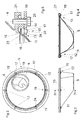
- the funnel-shaped outlet part 11 of the metering device 5 has a designed as a circular ring 14 sliding bearing surface which is arranged in a collar-like manner on the outlet part 11 of the metering device 5.
- the trained as a circular ring 14 plain bearing surface is mounted on the storage container 2 arranged bearing surface elements 15.
- These bearing surface elements 15 each have only an enlarged, flattened spherical or hemispherical bearing surface 16. Trained as a circular ring 14 sliding bearing surface is disposed resting on the bearing surface elements 15, which is the 4 and 5 demonstrate.
- the bearing surface elements 15 are designed as a bolt 17 with a flattened spherical or hemispherical and enlarged point-like support surface 16. This bearing surface 16 is formed opposite the bolt 17 as an enlarged bolt head 18, as the Fig. 5 shows.
- the bearing surface elements 15 are spaced from each other on a circular retaining ring 19, which is arranged by means of fastening 20 and spacer elements 21 at the lower portion 4 of the reservoir 2, respectively.
- the fastening means 20 here are designed as screws.
- the bearing surface elements 15 are made of a good Slippery material, for example, a Teflon blended steel made.
- the bolt head 18 is hemispherical shaped with a flattened portion 22 forming the respective enlarged point-like bearing surface Fig. 5 shows.
- the sliding bearing surface consists on the one hand of a sheet-like circular ring 19, which is arranged as mentioned in a collar-like manner on the metering device 5. Furthermore, the sliding bearing surface consists of a ring-like bearing ring 23, which adjoins at an angle on the inside of the circular ring 19 serving as a sliding bearing surface and consists of an integrally formed region of the funnel-shaped lower part 11 of the metering device 5.
- the serving as a bearing surface element 15 bolt head 18 is associated with the annulus 19 and the bearing ring 23 in an adjacent manner, so that a good rotation of the dosing device 5 is achieved.
- the trained as a bolt 17 with bolt head 18 bearing surface elements 15 are spaced from each other.
- the fastening means 20 are each arranged adjacent to a bearing surface element 15, such as Fig. 3 shows.
- the formed as a bolt 17 bearing surface elements 15 are arranged on the retaining ring 19 relative to the inner edge of the retaining ring 19 inwardly on tongue-like protruding portions 24 of the retaining ring 19, such as Fig. 3 shows.
Landscapes
- Life Sciences & Earth Sciences (AREA)
- Soil Sciences (AREA)
- Environmental Sciences (AREA)
- Fertilizing (AREA)
Claims (10)
- Épandeur centrifuge comprenant un réservoir (2) qui comprend au moins une partie inférieure (4) se rétrécissant de manière à former un entonnoir, laquelle est fermée par un dispositif de dosage (5) disposé sur la partie inférieure (4) de manière à pouvoir tourner autour d'un axe vertical (13) au moyen d'un palier lisse (12), caractérisé en ce que le palier lisse (12) comprend des éléments de surface de palier (15) fixés à la partie inférieure (4), supportant le dispositif de dosage (5) par le dessous et disposés sur un cercle, les éléments de surface de palier (15) ne comprenant respectivement qu'une surface d'appui (16) agrandie ponctuelle, en particulier aplatie hémisphérique.
- Épandeur centrifuge selon la revendication 1, caractérisé en ce que le dispositif de dosage (5) comprend au moins une surface de palier lisse (14), et en ce que la surface de palier lisse (14) est disposée de manière à reposer sur les éléments de surface de palier (15).
- Épandeur centrifuge selon l'une quelconque ou plusieurs des revendications précédentes, caractérisé en ce que la surface de palier lisse est réalisée sous forme de bague circulaire (14).
- Épandeur centrifuge selon au moins l'une quelconque des revendications précédentes, caractérisé en ce que la surface de palier lisse (14) est disposée en forme de collerette sur le dispositif de dosage (5).
- Épandeur centrifuge selon au moins l'une quelconque des revendications précédentes, caractérisé en ce que les éléments de surface de palier (15) sont réalisés sous forme de boulons (17) dotés d'une tête de boulon (18) agrandie par rapport au boulon (17) et servant de surface d'appui (16) aplatie hémisphérique et/ou agrandie ponctuelle.
- Épandeur centrifuge selon l'une quelconque ou plusieurs des revendications précédentes, caractérisé en ce que les éléments de surface de palier (15) sont fixés de manière espacée les uns des autres sur une bague de retenue circulaire (19), et en ce que la bague de retenue (19) est fixée à la partie inférieure (4) par le biais de moyens de fixation (20).
- Épandeur centrifuge selon au moins l'une quelconque des revendications précédentes, caractérisé en ce que les éléments de surface de palier (15) sont fabriqués à partir d'un matériau présentant de bonnes propriétés de glissement.
- Épandeur centrifuge selon la revendication 5, caractérisé en ce que la tête de boulon (18) est réalisée de manière hémisphérique avec une région aplatie (22) qui forme la surface d'appui (16) agrandie ponctuelle.
- Épandeur centrifuge selon au moins l'une quelconque des revendications précédentes, caractérisé en ce que la surface de palier lisse est constituée d'une bague circulaire (14) de type surface, qui est disposée en forme de collerette sur le dispositif de dosage (5), et d'une bague de palier (23) annulaire se raccordant suivant un angle sur le côté intérieur et/ou extérieur de la bague circulaire (14), et en ce que les éléments de surface de palier (15) sont associés à la bague de retenue (19) de manière à s'appliquer contre la bague circulaire (14) et la bague de palier (23).
- Épandeur centrifuge selon au moins l'une quelconque des revendications précédentes, caractérisé en ce que les moyens de fixation (20) sont disposés de manière respectivement adjacente à un élément de surface de palier (15), et en ce que les éléments de surface de palier (15) sont disposés sur la bague de retenue (19) en regard du bord intérieur de la bague de retenue (19) sur des régions (24) faisant saillie à la manière de languettes de la bague de retenue (19).
Applications Claiming Priority (1)
| Application Number | Priority Date | Filing Date | Title |
|---|---|---|---|
| DE102009044311A DE102009044311A1 (de) | 2009-10-22 | 2009-10-22 | Schleuderstreuer |
Publications (2)
| Publication Number | Publication Date |
|---|---|
| EP2314143A1 EP2314143A1 (fr) | 2011-04-27 |
| EP2314143B1 true EP2314143B1 (fr) | 2015-04-22 |
Family
ID=43608770
Family Applications (1)
| Application Number | Title | Priority Date | Filing Date |
|---|---|---|---|
| EP20100401178 Active EP2314143B1 (fr) | 2009-10-22 | 2010-10-18 | Epandeur centrifuge |
Country Status (3)
| Country | Link |
|---|---|
| EP (1) | EP2314143B1 (fr) |
| DE (1) | DE102009044311A1 (fr) |
| DK (1) | DK2314143T3 (fr) |
Families Citing this family (1)
| Publication number | Priority date | Publication date | Assignee | Title |
|---|---|---|---|---|
| CN112913421B (zh) * | 2021-01-27 | 2023-05-02 | 山东省农业机械科学研究院 | 一种电驱式精量定位排肥器、设备及方法 |
Family Cites Families (2)
| Publication number | Priority date | Publication date | Assignee | Title |
|---|---|---|---|---|
| DE102005030781B4 (de) | 2005-07-01 | 2018-05-30 | Rauch Landmaschinenfabrik Gmbh | Schleuderstreuer für Streugut |
| DE102006045284A1 (de) * | 2006-09-22 | 2008-04-03 | Rauch Landmaschinenfabrik Gmbh | Schleuderstreuer für Streugut |
-
2009
- 2009-10-22 DE DE102009044311A patent/DE102009044311A1/de not_active Withdrawn
-
2010
- 2010-10-18 EP EP20100401178 patent/EP2314143B1/fr active Active
- 2010-10-18 DK DK10401178.8T patent/DK2314143T3/en active
Also Published As
| Publication number | Publication date |
|---|---|
| DE102009044311A1 (de) | 2011-04-28 |
| DK2314143T3 (en) | 2015-06-15 |
| EP2314143A1 (fr) | 2011-04-27 |
Similar Documents
| Publication | Publication Date | Title |
|---|---|---|
| EP3127414B1 (fr) | Groupe de dosage pour semences | |
| DE102013110991B3 (de) | Dosiersystem einer landwirtschaftlichen Verteilmaschine | |
| DE102008037397A1 (de) | Einzelkorndosiervorrichtung | |
| DE3218196C1 (de) | Dosiergeraet fuer Verteilersysteme fuer koernige Stoffe,wie Saatgut oder Duenger | |
| EP2989877A1 (fr) | Groupe de dosage pour matériau granulaire | |
| DE2242272A1 (de) | Einzelkornsaemaschine | |
| EP0410112B1 (fr) | Epandeur centrifuge pour matériau coulant, en particulier engrais | |
| DE2848858C2 (de) | Formsandmischer zur Verarbeitung eines Zweikomponenten-Bindemittels | |
| DE1657004A1 (de) | Streugeraet | |
| EP2314143A1 (fr) | Epandeur centrifuge | |
| DE102019104425A1 (de) | Dosiereinrichtung für körniges Gut und Verteilmaschine mit Dosiereinrichtung | |
| EP2332401B1 (fr) | Epandeur d'engrais centrifuge | |
| EP2311303B1 (fr) | Epandeur d'engrais centrifuge | |
| EP3339817B1 (fr) | Dispositif de dosage pour substances en poudre | |
| DE1924631C3 (de) | Streugerät | |
| EP3811752A1 (fr) | Machine d'épandage | |
| EP2316258B1 (fr) | Epandeur d'engrais centrifuge | |
| DE202012102931U1 (de) | Austragsvorrichtung für einen Schüttgutbehälter | |
| DE102008020020A1 (de) | Zentrifugalstreuer | |
| DE8910777U1 (de) | Vorrichtung zum Verteilen von inhomogenen, feststoffbeladenen Flüssigkeiten, insbesondere Gülle | |
| EP2547190B1 (fr) | Épandeur à double disque | |
| DE965174C (de) | Saemaschine | |
| DE7115099U (de) | Streugerat | |
| DE102005010876A1 (de) | Innenbelüftete Schleifvorrichtung | |
| DE3128113A1 (de) | Verstellbare banduebergabe zur verwendung im untertaegigen grubenbetrieb, mit einer um 360 grad um einen mittelpunkt stufenlos drehbaren schurre |
Legal Events
| Date | Code | Title | Description |
|---|---|---|---|
| PUAI | Public reference made under article 153(3) epc to a published international application that has entered the european phase |
Free format text: ORIGINAL CODE: 0009012 |
|
| AK | Designated contracting states |
Kind code of ref document: A1 Designated state(s): AL AT BE BG CH CY CZ DE DK EE ES FI FR GB GR HR HU IE IS IT LI LT LU LV MC MK MT NL NO PL PT RO RS SE SI SK SM TR |
|
| AX | Request for extension of the european patent |
Extension state: BA ME |
|
| 17P | Request for examination filed |
Effective date: 20110601 |
|
| GRAP | Despatch of communication of intention to grant a patent |
Free format text: ORIGINAL CODE: EPIDOSNIGR1 |
|
| INTG | Intention to grant announced |
Effective date: 20150202 |
|
| GRAS | Grant fee paid |
Free format text: ORIGINAL CODE: EPIDOSNIGR3 |
|
| GRAA | (expected) grant |
Free format text: ORIGINAL CODE: 0009210 |
|
| AK | Designated contracting states |
Kind code of ref document: B1 Designated state(s): AL AT BE BG CH CY CZ DE DK EE ES FI FR GB GR HR HU IE IS IT LI LT LU LV MC MK MT NL NO PL PT RO RS SE SI SK SM TR |
|
| REG | Reference to a national code |
Ref country code: GB Ref legal event code: FG4D Free format text: NOT ENGLISH |
|
| REG | Reference to a national code |
Ref country code: CH Ref legal event code: EP |
|
| REG | Reference to a national code |
Ref country code: AT Ref legal event code: REF Ref document number: 722609 Country of ref document: AT Kind code of ref document: T Effective date: 20150515 |
|
| REG | Reference to a national code |
Ref country code: IE Ref legal event code: FG4D Free format text: LANGUAGE OF EP DOCUMENT: GERMAN |
|
| REG | Reference to a national code |
Ref country code: DE Ref legal event code: R096 Ref document number: 502010009387 Country of ref document: DE Effective date: 20150603 |
|
| REG | Reference to a national code |
Ref country code: DK Ref legal event code: T3 Effective date: 20150612 |
|
| REG | Reference to a national code |
Ref country code: NL Ref legal event code: T3 |
|
| REG | Reference to a national code |
Ref country code: LT Ref legal event code: MG4D |
|
| PG25 | Lapsed in a contracting state [announced via postgrant information from national office to epo] |
Ref country code: NO Free format text: LAPSE BECAUSE OF FAILURE TO SUBMIT A TRANSLATION OF THE DESCRIPTION OR TO PAY THE FEE WITHIN THE PRESCRIBED TIME-LIMIT Effective date: 20150722 Ref country code: HR Free format text: LAPSE BECAUSE OF FAILURE TO SUBMIT A TRANSLATION OF THE DESCRIPTION OR TO PAY THE FEE WITHIN THE PRESCRIBED TIME-LIMIT Effective date: 20150422 Ref country code: ES Free format text: LAPSE BECAUSE OF FAILURE TO SUBMIT A TRANSLATION OF THE DESCRIPTION OR TO PAY THE FEE WITHIN THE PRESCRIBED TIME-LIMIT Effective date: 20150422 Ref country code: FI Free format text: LAPSE BECAUSE OF FAILURE TO SUBMIT A TRANSLATION OF THE DESCRIPTION OR TO PAY THE FEE WITHIN THE PRESCRIBED TIME-LIMIT Effective date: 20150422 Ref country code: LT Free format text: LAPSE BECAUSE OF FAILURE TO SUBMIT A TRANSLATION OF THE DESCRIPTION OR TO PAY THE FEE WITHIN THE PRESCRIBED TIME-LIMIT Effective date: 20150422 Ref country code: PT Free format text: LAPSE BECAUSE OF FAILURE TO SUBMIT A TRANSLATION OF THE DESCRIPTION OR TO PAY THE FEE WITHIN THE PRESCRIBED TIME-LIMIT Effective date: 20150824 |
|
| PG25 | Lapsed in a contracting state [announced via postgrant information from national office to epo] |
Ref country code: RS Free format text: LAPSE BECAUSE OF FAILURE TO SUBMIT A TRANSLATION OF THE DESCRIPTION OR TO PAY THE FEE WITHIN THE PRESCRIBED TIME-LIMIT Effective date: 20150422 Ref country code: LV Free format text: LAPSE BECAUSE OF FAILURE TO SUBMIT A TRANSLATION OF THE DESCRIPTION OR TO PAY THE FEE WITHIN THE PRESCRIBED TIME-LIMIT Effective date: 20150422 Ref country code: IS Free format text: LAPSE BECAUSE OF FAILURE TO SUBMIT A TRANSLATION OF THE DESCRIPTION OR TO PAY THE FEE WITHIN THE PRESCRIBED TIME-LIMIT Effective date: 20150822 Ref country code: GR Free format text: LAPSE BECAUSE OF FAILURE TO SUBMIT A TRANSLATION OF THE DESCRIPTION OR TO PAY THE FEE WITHIN THE PRESCRIBED TIME-LIMIT Effective date: 20150723 |
|
| REG | Reference to a national code |
Ref country code: DE Ref legal event code: R097 Ref document number: 502010009387 Country of ref document: DE |
|
| PG25 | Lapsed in a contracting state [announced via postgrant information from national office to epo] |
Ref country code: EE Free format text: LAPSE BECAUSE OF FAILURE TO SUBMIT A TRANSLATION OF THE DESCRIPTION OR TO PAY THE FEE WITHIN THE PRESCRIBED TIME-LIMIT Effective date: 20150422 |
|
| PLBE | No opposition filed within time limit |
Free format text: ORIGINAL CODE: 0009261 |
|
| STAA | Information on the status of an ep patent application or granted ep patent |
Free format text: STATUS: NO OPPOSITION FILED WITHIN TIME LIMIT |
|
| PG25 | Lapsed in a contracting state [announced via postgrant information from national office to epo] |
Ref country code: PL Free format text: LAPSE BECAUSE OF FAILURE TO SUBMIT A TRANSLATION OF THE DESCRIPTION OR TO PAY THE FEE WITHIN THE PRESCRIBED TIME-LIMIT Effective date: 20150422 Ref country code: CZ Free format text: LAPSE BECAUSE OF FAILURE TO SUBMIT A TRANSLATION OF THE DESCRIPTION OR TO PAY THE FEE WITHIN THE PRESCRIBED TIME-LIMIT Effective date: 20150422 Ref country code: SK Free format text: LAPSE BECAUSE OF FAILURE TO SUBMIT A TRANSLATION OF THE DESCRIPTION OR TO PAY THE FEE WITHIN THE PRESCRIBED TIME-LIMIT Effective date: 20150422 Ref country code: RO Free format text: LAPSE BECAUSE OF NON-PAYMENT OF DUE FEES Effective date: 20150422 |
|
| 26N | No opposition filed |
Effective date: 20160125 |
|
| PG25 | Lapsed in a contracting state [announced via postgrant information from national office to epo] |
Ref country code: SI Free format text: LAPSE BECAUSE OF FAILURE TO SUBMIT A TRANSLATION OF THE DESCRIPTION OR TO PAY THE FEE WITHIN THE PRESCRIBED TIME-LIMIT Effective date: 20150422 Ref country code: LU Free format text: LAPSE BECAUSE OF FAILURE TO SUBMIT A TRANSLATION OF THE DESCRIPTION OR TO PAY THE FEE WITHIN THE PRESCRIBED TIME-LIMIT Effective date: 20151018 |
|
| REG | Reference to a national code |
Ref country code: CH Ref legal event code: PL |
|
| GBPC | Gb: european patent ceased through non-payment of renewal fee |
Effective date: 20151018 |
|
| PG25 | Lapsed in a contracting state [announced via postgrant information from national office to epo] |
Ref country code: MC Free format text: LAPSE BECAUSE OF FAILURE TO SUBMIT A TRANSLATION OF THE DESCRIPTION OR TO PAY THE FEE WITHIN THE PRESCRIBED TIME-LIMIT Effective date: 20150422 |
|
| REG | Reference to a national code |
Ref country code: IE Ref legal event code: MM4A |
|
| PG25 | Lapsed in a contracting state [announced via postgrant information from national office to epo] |
Ref country code: CH Free format text: LAPSE BECAUSE OF NON-PAYMENT OF DUE FEES Effective date: 20151031 Ref country code: GB Free format text: LAPSE BECAUSE OF NON-PAYMENT OF DUE FEES Effective date: 20151018 Ref country code: LI Free format text: LAPSE BECAUSE OF NON-PAYMENT OF DUE FEES Effective date: 20151031 |
|
| REG | Reference to a national code |
Ref country code: FR Ref legal event code: PLFP Year of fee payment: 7 |
|
| PG25 | Lapsed in a contracting state [announced via postgrant information from national office to epo] |
Ref country code: IE Free format text: LAPSE BECAUSE OF NON-PAYMENT OF DUE FEES Effective date: 20151018 |
|
| REG | Reference to a national code |
Ref country code: AT Ref legal event code: MM01 Ref document number: 722609 Country of ref document: AT Kind code of ref document: T Effective date: 20151018 |
|
| PG25 | Lapsed in a contracting state [announced via postgrant information from national office to epo] |
Ref country code: AT Free format text: LAPSE BECAUSE OF NON-PAYMENT OF DUE FEES Effective date: 20151018 |
|
| PG25 | Lapsed in a contracting state [announced via postgrant information from national office to epo] |
Ref country code: HU Free format text: LAPSE BECAUSE OF FAILURE TO SUBMIT A TRANSLATION OF THE DESCRIPTION OR TO PAY THE FEE WITHIN THE PRESCRIBED TIME-LIMIT; INVALID AB INITIO Effective date: 20101018 Ref country code: BG Free format text: LAPSE BECAUSE OF FAILURE TO SUBMIT A TRANSLATION OF THE DESCRIPTION OR TO PAY THE FEE WITHIN THE PRESCRIBED TIME-LIMIT Effective date: 20150422 Ref country code: SM Free format text: LAPSE BECAUSE OF FAILURE TO SUBMIT A TRANSLATION OF THE DESCRIPTION OR TO PAY THE FEE WITHIN THE PRESCRIBED TIME-LIMIT Effective date: 20150422 |
|
| PG25 | Lapsed in a contracting state [announced via postgrant information from national office to epo] |
Ref country code: SE Free format text: LAPSE BECAUSE OF FAILURE TO SUBMIT A TRANSLATION OF THE DESCRIPTION OR TO PAY THE FEE WITHIN THE PRESCRIBED TIME-LIMIT Effective date: 20150422 Ref country code: CY Free format text: LAPSE BECAUSE OF FAILURE TO SUBMIT A TRANSLATION OF THE DESCRIPTION OR TO PAY THE FEE WITHIN THE PRESCRIBED TIME-LIMIT Effective date: 20150422 |
|
| PG25 | Lapsed in a contracting state [announced via postgrant information from national office to epo] |
Ref country code: BE Free format text: LAPSE BECAUSE OF NON-PAYMENT OF DUE FEES Effective date: 20151031 |
|
| PG25 | Lapsed in a contracting state [announced via postgrant information from national office to epo] |
Ref country code: MT Free format text: LAPSE BECAUSE OF FAILURE TO SUBMIT A TRANSLATION OF THE DESCRIPTION OR TO PAY THE FEE WITHIN THE PRESCRIBED TIME-LIMIT Effective date: 20150422 Ref country code: TR Free format text: LAPSE BECAUSE OF FAILURE TO SUBMIT A TRANSLATION OF THE DESCRIPTION OR TO PAY THE FEE WITHIN THE PRESCRIBED TIME-LIMIT Effective date: 20150422 |
|
| REG | Reference to a national code |
Ref country code: FR Ref legal event code: PLFP Year of fee payment: 8 |
|
| PG25 | Lapsed in a contracting state [announced via postgrant information from national office to epo] |
Ref country code: MK Free format text: LAPSE BECAUSE OF FAILURE TO SUBMIT A TRANSLATION OF THE DESCRIPTION OR TO PAY THE FEE WITHIN THE PRESCRIBED TIME-LIMIT Effective date: 20150422 |
|
| REG | Reference to a national code |
Ref country code: FR Ref legal event code: PLFP Year of fee payment: 9 |
|
| PG25 | Lapsed in a contracting state [announced via postgrant information from national office to epo] |
Ref country code: AL Free format text: LAPSE BECAUSE OF FAILURE TO SUBMIT A TRANSLATION OF THE DESCRIPTION OR TO PAY THE FEE WITHIN THE PRESCRIBED TIME-LIMIT Effective date: 20150422 |
|
| REG | Reference to a national code |
Ref country code: DE Ref legal event code: R082 Ref document number: 502010009387 Country of ref document: DE Representative=s name: KILBURN & STRODE LLP, GB Ref country code: DE Ref legal event code: R082 Ref document number: 502010009387 Country of ref document: DE Representative=s name: KILBURN & STRODE LLP, NL Ref country code: DE Ref legal event code: R081 Ref document number: 502010009387 Country of ref document: DE Owner name: AMAZONEN-WERKE H. DREYER SE & CO. KG, DE Free format text: FORMER OWNER: AMAZONEN-WERKE H. DREYER GMBH & CO. KG, 49205 HASBERGEN, DE |
|
| REG | Reference to a national code |
Ref country code: DE Ref legal event code: R082 Ref document number: 502010009387 Country of ref document: DE Representative=s name: KILBURN & STRODE LLP, NL |
|
| P01 | Opt-out of the competence of the unified patent court (upc) registered |
Effective date: 20230523 |
|
| PGFP | Annual fee paid to national office [announced via postgrant information from national office to epo] |
Ref country code: NL Payment date: 20250912 Year of fee payment: 16 Ref country code: IT Payment date: 20250922 Year of fee payment: 16 |
|
| PGFP | Annual fee paid to national office [announced via postgrant information from national office to epo] |
Ref country code: FR Payment date: 20250908 Year of fee payment: 16 |
|
| PGFP | Annual fee paid to national office [announced via postgrant information from national office to epo] |
Ref country code: DE Payment date: 20250902 Year of fee payment: 16 |
|
| PGFP | Annual fee paid to national office [announced via postgrant information from national office to epo] |
Ref country code: DK Payment date: 20251014 Year of fee payment: 16 |