EP2314268B1 - Kompressionsbehandlungssystem - Google Patents
Kompressionsbehandlungssystem Download PDFInfo
- Publication number
- EP2314268B1 EP2314268B1 EP10185260.6A EP10185260A EP2314268B1 EP 2314268 B1 EP2314268 B1 EP 2314268B1 EP 10185260 A EP10185260 A EP 10185260A EP 2314268 B1 EP2314268 B1 EP 2314268B1
- Authority
- EP
- European Patent Office
- Prior art keywords
- sleeve
- pressure
- bladder
- pump
- compression
- Prior art date
- Legal status (The legal status is an assumption and is not a legal conclusion. Google has not performed a legal analysis and makes no representation as to the accuracy of the status listed.)
- Expired - Lifetime
Links
Images


Classifications
-
- A—HUMAN NECESSITIES
- A61—MEDICAL OR VETERINARY SCIENCE; HYGIENE
- A61H—PHYSICAL THERAPY APPARATUS, e.g. DEVICES FOR LOCATING OR STIMULATING REFLEX POINTS IN THE BODY; ARTIFICIAL RESPIRATION; MASSAGE; BATHING DEVICES FOR SPECIAL THERAPEUTIC OR HYGIENIC PURPOSES OR SPECIFIC PARTS OF THE BODY
- A61H23/00—Percussion or vibration massage, e.g. using supersonic vibration; Suction-vibration massage; Massage with moving diaphragms
- A61H23/04—Percussion or vibration massage, e.g. using supersonic vibration; Suction-vibration massage; Massage with moving diaphragms with hydraulic or pneumatic drive
-
- A—HUMAN NECESSITIES
- A61—MEDICAL OR VETERINARY SCIENCE; HYGIENE
- A61H—PHYSICAL THERAPY APPARATUS, e.g. DEVICES FOR LOCATING OR STIMULATING REFLEX POINTS IN THE BODY; ARTIFICIAL RESPIRATION; MASSAGE; BATHING DEVICES FOR SPECIAL THERAPEUTIC OR HYGIENIC PURPOSES OR SPECIFIC PARTS OF THE BODY
- A61H9/00—Pneumatic or hydraulic massage
- A61H9/005—Pneumatic massage
- A61H9/0078—Pneumatic massage with intermittent or alternately inflated bladders or cuffs
-
- A—HUMAN NECESSITIES
- A61—MEDICAL OR VETERINARY SCIENCE; HYGIENE
- A61H—PHYSICAL THERAPY APPARATUS, e.g. DEVICES FOR LOCATING OR STIMULATING REFLEX POINTS IN THE BODY; ARTIFICIAL RESPIRATION; MASSAGE; BATHING DEVICES FOR SPECIAL THERAPEUTIC OR HYGIENIC PURPOSES OR SPECIFIC PARTS OF THE BODY
- A61H2201/00—Characteristics of apparatus not provided for in the preceding codes
- A61H2201/16—Physical interface with patient
- A61H2201/1602—Physical interface with patient kind of interface, e.g. head rest, knee support or lumbar support
- A61H2201/1645—Physical interface with patient kind of interface, e.g. head rest, knee support or lumbar support contoured to fit the user
-
- A—HUMAN NECESSITIES
- A61—MEDICAL OR VETERINARY SCIENCE; HYGIENE
- A61H—PHYSICAL THERAPY APPARATUS, e.g. DEVICES FOR LOCATING OR STIMULATING REFLEX POINTS IN THE BODY; ARTIFICIAL RESPIRATION; MASSAGE; BATHING DEVICES FOR SPECIAL THERAPEUTIC OR HYGIENIC PURPOSES OR SPECIFIC PARTS OF THE BODY
- A61H2201/00—Characteristics of apparatus not provided for in the preceding codes
- A61H2201/16—Physical interface with patient
- A61H2201/1683—Surface of interface
- A61H2201/169—Physical characteristics of the surface, e.g. material, relief, texture or indicia
- A61H2201/1697—Breathability of the material
-
- A—HUMAN NECESSITIES
- A61—MEDICAL OR VETERINARY SCIENCE; HYGIENE
- A61H—PHYSICAL THERAPY APPARATUS, e.g. DEVICES FOR LOCATING OR STIMULATING REFLEX POINTS IN THE BODY; ARTIFICIAL RESPIRATION; MASSAGE; BATHING DEVICES FOR SPECIAL THERAPEUTIC OR HYGIENIC PURPOSES OR SPECIFIC PARTS OF THE BODY
- A61H2201/00—Characteristics of apparatus not provided for in the preceding codes
- A61H2201/50—Control means thereof
- A61H2201/5002—Means for controlling a set of similar massage devices acting in sequence at different locations on a patient
-
- A—HUMAN NECESSITIES
- A61—MEDICAL OR VETERINARY SCIENCE; HYGIENE
- A61H—PHYSICAL THERAPY APPARATUS, e.g. DEVICES FOR LOCATING OR STIMULATING REFLEX POINTS IN THE BODY; ARTIFICIAL RESPIRATION; MASSAGE; BATHING DEVICES FOR SPECIAL THERAPEUTIC OR HYGIENIC PURPOSES OR SPECIFIC PARTS OF THE BODY
- A61H2201/00—Characteristics of apparatus not provided for in the preceding codes
- A61H2201/50—Control means thereof
- A61H2201/5007—Control means thereof computer controlled
-
- A—HUMAN NECESSITIES
- A61—MEDICAL OR VETERINARY SCIENCE; HYGIENE
- A61H—PHYSICAL THERAPY APPARATUS, e.g. DEVICES FOR LOCATING OR STIMULATING REFLEX POINTS IN THE BODY; ARTIFICIAL RESPIRATION; MASSAGE; BATHING DEVICES FOR SPECIAL THERAPEUTIC OR HYGIENIC PURPOSES OR SPECIFIC PARTS OF THE BODY
- A61H2201/00—Characteristics of apparatus not provided for in the preceding codes
- A61H2201/50—Control means thereof
- A61H2201/5058—Sensors or detectors
- A61H2201/5071—Pressure sensors
-
- A—HUMAN NECESSITIES
- A61—MEDICAL OR VETERINARY SCIENCE; HYGIENE
- A61H—PHYSICAL THERAPY APPARATUS, e.g. DEVICES FOR LOCATING OR STIMULATING REFLEX POINTS IN THE BODY; ARTIFICIAL RESPIRATION; MASSAGE; BATHING DEVICES FOR SPECIAL THERAPEUTIC OR HYGIENIC PURPOSES OR SPECIFIC PARTS OF THE BODY
- A61H2205/00—Devices for specific parts of the body
- A61H2205/06—Arms
-
- A—HUMAN NECESSITIES
- A61—MEDICAL OR VETERINARY SCIENCE; HYGIENE
- A61H—PHYSICAL THERAPY APPARATUS, e.g. DEVICES FOR LOCATING OR STIMULATING REFLEX POINTS IN THE BODY; ARTIFICIAL RESPIRATION; MASSAGE; BATHING DEVICES FOR SPECIAL THERAPEUTIC OR HYGIENIC PURPOSES OR SPECIFIC PARTS OF THE BODY
- A61H2205/00—Devices for specific parts of the body
- A61H2205/10—Leg
-
- A—HUMAN NECESSITIES
- A61—MEDICAL OR VETERINARY SCIENCE; HYGIENE
- A61H—PHYSICAL THERAPY APPARATUS, e.g. DEVICES FOR LOCATING OR STIMULATING REFLEX POINTS IN THE BODY; ARTIFICIAL RESPIRATION; MASSAGE; BATHING DEVICES FOR SPECIAL THERAPEUTIC OR HYGIENIC PURPOSES OR SPECIFIC PARTS OF THE BODY
- A61H2205/00—Devices for specific parts of the body
- A61H2205/12—Feet
-
- A—HUMAN NECESSITIES
- A61—MEDICAL OR VETERINARY SCIENCE; HYGIENE
- A61H—PHYSICAL THERAPY APPARATUS, e.g. DEVICES FOR LOCATING OR STIMULATING REFLEX POINTS IN THE BODY; ARTIFICIAL RESPIRATION; MASSAGE; BATHING DEVICES FOR SPECIAL THERAPEUTIC OR HYGIENIC PURPOSES OR SPECIFIC PARTS OF THE BODY
- A61H2209/00—Devices for avoiding blood stagnation, e.g. Deep Vein Thrombosis [DVT] devices
Definitions
- the present disclosure generally relates to the field of vascular therapy for application to a limb of a body, and more particularly, to a compression treatment system having a controller that regulates fluid flow.
- a major concern for immobile patients and persons alike are medical conditions that form clots in the blood, such as, deep vein thrombosis (DVT) and peripheral edema.
- DVT deep vein thrombosis
- Such patients and persons include those undergoing surgery, anesthesia, extended periods of bed rest, etc.
- These blood clotting conditions generally occur in the deep veins of the lower extremities and/or pelvis.
- These veins such as the iliac, femoral, popiteal and tibial return deoxygenated blood to the heart.
- a static pool of blood is ideal for clot formations.
- a major risk associated with this condition is interference with cardiovascular circulation. Most seriously, a fragment of the blood clot can break loose and migrate.
- a pulmonary emboli can form blocking a main pulmonary artery, which may be life threatening.
- the conditions and resulting risks associated with patient immobility may be controlled or alleviated by applying intermittent pressure to a patient's limb, such as, for example, a leg including the thigh, calf and foot to assist in blood circulation.
- a patient's limb such as, for example, a leg including the thigh, calf and foot
- Known devices have been employed to assist in blood circulation, such as, one piece pads and compression boots. See, for example, U.S. Patent Nos. 6,290,662 and 6,494,852 .
- sequential compression devices consist of an air pump connected to a disposable wraparound pad by a series of air tubes.
- the wraparound pad is configured for placement about a portion of a patient's leg, such as the thigh, calf or foot. Multiple pads may be mounted to the leg to cover the various portions of the leg. Air is then forced into different parts of the wraparound pad(s) in sequence, creating pressure around the thigh, calf or foot, thereby improving venous return.
- US 5575762 discloses a compression treatment system according to the preamble of claim 1. It discloses a gradient sequential compression system for preventing deep vein thrombosis including a pressure-based system controller for controlling transfers of air from a source of pressurized air to inflatable chambers of a limb sleeve, so that prophylactic modality is provided to the limb.
- the system controller includes means for detecting low and high pressure fault conditions which can be caused by disconnected or occluded conduits, and sleeves that are wrapped too loosely or too tightly about a limb.”
- GB 2295235 discloses an inflatable garment for applying compression to the limb of a patient which has two inflatable chambers for each limb. Both the lower and upper chambers are directly connected sequentially to a common source of inflation. A non-return valve prevents any deflation of the first chamber when beginning to inflate the second chamber. Pressure in the chambers is monitored by pressure transducers. A microprocessor is programmed to activate an alarm if the rate of increase in pressure falls outside a predetermined limit rate.
- EP 1226804 discloses a pressure applying apparatus comprising a compression sleeve with a plurality of inflatable annular cells, a control block with pneumatic valves connected to said annular cells and a pressurized fluid source connected to said control block, which is adapted to perform with said sleeve a regular compression procedure.
- EP 1226804 discloses a scanning of cells by applying low pressure to each cell. The scanning detects the number of cells in the sleeve and adjusts the device operation accordingly. The scanning procedure is also used to detect malfunctioning cells.
- such known sequential compression devices typically include a controller assembly that regulates air flow and pressure in the wraparound pad(s).
- the controller assembly can be mounted to a bed and plugged into a wall outlet for power during use.
- This arrangement can present challenges for example, when the patient needs to perform certain tasks, e.g., bathroom, physical therapy, etc. In these situations, the pads are usually removed, thus disadvantageously discontinuing vascular therapy.
- these controller assemblies suffer from various drawbacks because they do not accommodate patient transport or mobility and are not typically adaptable for inflation of thigh, calf and foot pads.
- a compression treatment system having a controller that is adaptable for inflating thigh, calf and foot sleeves and accommodates patient transport and mobility to provide continuous vascular therapy. It would be desirable if the system automatically detects the types of sleeves connected thereto. It would be highly desirable if the system included a pneumatic circuit that facilitates pressure monitoring with a single pressure transducer to achieve the advantages of the present disclosure. It is contemplated that the compression treatment system is easily and efficiently manufactured.
- a compression treatment system as claimed in claim 1 is provided.
- the exemplary embodiments of the compression treatment system and methods of operation disclosed are discussed in terms of vascular therapy including a prophylaxis compression apparatus for application to a limb of a body and more particularly in terms of a compression treatment system having a controller that is adaptable for inflating thigh, calf, ankle and foot sleeves and accommodates patient transport and mobility. It is contemplated that the compression treatment system may be employed for preventing and overcoming the risks associated with patient immobility. It is further contemplated that the compression treatment system alleviates the conditions arising from patient immobility to prevent for example, DVT, peripheral edema, etc.
- the compression treatment system according to the present disclosure may be attributable to all types of venous compression systems, including, but not limited to a prophylaxis sequential compression apparatus.
- prophylaxis sequential shall not be construed as limiting the general venous compression treatment system described herein. It is envisioned that the present disclosure, however, finds application with a wide variety of immobile conditions of persons and patients alike, such as, for example, those undergoing surgery, anesthesia, extended periods of bed rest, obesity, advanced age, malignancy, prior thromboembolism, etc.
- proximal refers to a portion of a structure that is closer to a torso of a subject and the term “distal” refers to a portion that is further from the torso.
- distal refers to a portion that is further from the torso.
- subject refers to a patient undergoing vascular therapy using the compression treatment system.
- the term “practitioner” refers to an individual administering the compression treatment system and may include support personnel.
- Compression treatment system 10 includes a housing 12. Housing 12 encloses the components of a controller 14 (shown schematically in FIG. 5 ) disposed therein.
- Housing 12 has a semi-circular configuration and has a handle cutout 16 along its apex 18 to facilitate transport and subject mobility. It is envisioned that housing 12 may be variously configured and dimensioned such as, for example, rectangular, spherical, etc. It is further envisioned that housing 12 may be assembled by any appropriate process such as, for example, snap fit, adhesive, solvent weld, thermal weld, ultrasonic weld, screw, rivet, etc. Alternatively, housing 12 may be monolithically formed or integrally assembled of multiple housing sections and may be substantially transparent, opaque, etc. Housing 12 may include ribs, ridges, etc. to facilitate manipulation of compression treatment system 10.
- housing 12 can be fabricated from a material suitable for medical applications, such as, for example, polymerics or metals, such as stainless steel, depending on the particular medical application and/or preference of a clinician.
- a material suitable for medical applications such as, for example, polymerics or metals, such as stainless steel, depending on the particular medical application and/or preference of a clinician.
- Semi-rigid and rigid polymerics are contemplated for fabrication, as well as resilient materials, such as molded medical grade polypropylene.
- resilient materials such as molded medical grade polypropylene.
- Housing 12 is portable to facilitate continuous vascular therapy to a subject (not shown).
- Housing 12 includes a bracket 20 that facilitates releasable mounting of housing 12 with for example, a hospital bed, table, etc.
- Bracket 20 extends from a rear portion 22 of housing 12 and provides a hook configuration for suspending housing 12 from a subject's bed, etc. It is contemplated that bracket 20 may be suspended from various structure for releasable mounting of housing 12, or alternatively, that housing 12 does not include a bracket and may be placed on a floor or other supporting surface.
- housing 12 includes a shoulder strap 24, as shown in FIG. 2 , that allows housing 12 to be worn on the subject or practitioner during transport. Shoulder strap 24 may be employed with or without bracket 20 and may, for example, be secured to any portion of the housing 12 including handle 16.
- Compression treatment system 10 employs an electrical AC/DC switching power supply for operation of its components.
- a power cord 26 is connected to housing 12 for conducting power to the components of controller 14.
- Power cord 26 accesses an AC power supply via a wall outlet, etc.
- Controller 14 may include a transformer or other electronics for connecting to the power supply. It is envisioned that power cord 26 may be wrapped around bracket 20 for storage and during transport and subject mobility.
- compression treatment system 10 may include a storage capture mechanism that retains power cord 26 with housing 12. The storage capture mechanism may include an elastic cord, pulley, etc.
- Compression treatment system 10 also employs a battery 28 for powering the components of controller 14 to facilitate transport and subject mobility.
- Battery 28 is disposed within a battery compartment 30 of housing 12. It is contemplated that battery 28 may include one or a plurality of cells. The battery cells may be lithium-ion type, etc. It is further contemplated that battery 28 is rechargeable and may be employed for various ranges of operation time, such as, for example, 6 hours, 8 hours, 10 hours, etc. For example, power cord 26 may be unplugged and captured by the storage capture mechanism of housing 12. Compression treatment system 10 then runs on battery 28 power and the subject is ambulatory.
- compression treatment system 10 may include alternate sources of power supply, such as, for example, solar, non-electrical, etc., or alternatively may not include battery power.
- Housing 12 has a control panel 32 disposed on a front surface 34 thereof.
- Control panel 32 includes controls and indicators for operation of compression treatment system 10.
- Control panel 32 has an LED display 36 that provides status indicia, messages, etc. of the various components of system 10, such as, for example, power, battery, sleeve identification and connection, inflation, venting, venous refill, errors, etc.
- Control panel 32 also includes manually activated switches for powering system 10, etc. It is contemplated that such switches are membrane type actuated by finger pressure, etc.
- Rear portion 22 of housing 12 defines ports 38, 40 ( FIG. 4 ).
- Ports 38, 40 include output ports 38 a , 38 b , 38 c , and output ports 40 a, 40 b, 40 c , respectively.
- Output ports 38 a , 38 b , 38 c , and output ports 40 a, 40 b, 40 c are in fluid communication with inflatable chambers 46 a , 46 b, 46 c of a compression sleeve 46 and inflatable chambers 48 a , 48 b , 48 c of a compression sleeve 48, respectively, which are configured to fit around the legs of a subject, via a mating connector 42 and tubing set 44, as will be discussed.
- Output ports 38 a , 38 b , 38 c , 40 a, 40 b, 40 c are configured for connection to tubing set 44.
- Each of ports 38, 40 are connectable to a particular compression sleeve, for example, leg sleeve, foot sleeve, etc.
- Controller 14 includes a pressurized fluid source, such as, for example, a pump 50 that fluidly communicates with a valve manifold 52 for connection with ports 38, 40, as will be discussed.
- Pump 50 includes a motor that compresses air to valve manifold 52 via tubing or the like. The speed of the pump motor is electronically controlled to provide a corresponding compressor speed for respective output pressures as desired.
- a power supply board including the necessary electronics, circuitry, software, etc. known to one skilled in the art, is connected to the pump motor and other components of controller 14 to regulate power thereto.
- pump 50 may be a diaphragm pump.
- Controller 14 also includes a check valve 54 that prevents air leakage back through pump 50 when monitoring bladder pressure during venous refill detection, as will be discussed.
- a pressure relief valve 56 is disposed with the pneumatic circuit to protect against over pressure in the compression sleeves. Pressure relief valve 56 is configured to bleed excess air pressure if necessary. It is contemplated that various types of valves may be employed such as, for example, spring loaded plunger valves, etc.
- Valve manifold 52 includes solenoid valves 58 a , 58 b , 58 c , 60 a , 60 b, 60 c that are coupled to output ports 38 a , 38 b , 38 c , 40 a, 40 b, 40 c , respectively.
- Solenoid valves 58 a , 58 b , 58 c , 60 a , 60 b , 60 c each have an associated solenoid that is electrically driven via a control processor of controller 14.
- the solenoid is coupled to a valve seat of each particular solenoid valve 58 a , 58 b , 58 c , 60 a , 60 b , 60 c such that the seat is operative to open and close the respective solenoid valve upon actuation of the solenoid.
- the control processor of controller 14 includes the necessary electronics, circuitry, software, etc.
- solenoid valves 58 a , 58 b , 58 c , 60 a , 60 b, 60 c in response to varying conditions of compression treatment system 10 and other indications and measurements sensed by the components of controller 14. It is envisioned that one or a plurality of solenoid valves may be employed, or alternatively, that other types of valves may be used.
- Solenoid valves 58 a , 58 b , 58 c , 60 a , 60 b , 60 c and their associated valve components are mounted to ports 38, 40 on the interior of housing 12.
- Solenoid valves 58 a , 58 b , 58 c , 60 a , 60 b , 60 c are two position, three-way normally closed valves, which have openings 62 a, 62 b , 62 c , 64 a , 64 b , 64 c , respectively.
- openings 62 a, 62 b , 62 c , 64 a , 64 b , 64 c are blocked and air from compression sleeves 46, 48 flows back through output port 38 a , 38 b , 38 c , 40 a, 40 b , 40 c and through vent ports 66 a, 66 b, 66 c, 68 a , 68 b , 68 c of the associated valve to deflate inflatable chambers 46 a , 46 b, 46 c , 48 a , 48 b , 48 c .
- Solenoid valves 58 a , 58 b , 58 c , 60 a , 60 b , 60 c are operated in sequence to pressurize inflatable chambers 46 a , 46 b, 46 c , 48 a , 48 b , 48 c and provide sequential pressurization thereof and venting of the chambers under the control processor of controller 14. It is contemplated that solenoid valves 58 a , 58 b , 58 c, 60 a , 60 b , 60 c may be selectively actuated when cooling operation of the sleeves is desired, see for example, U.S. Patent No. 5,876,359 to Bock et al.
- Solenoid valves 58 a , 58 b , 58 c , 60 a , 60 b , 60 c are driven by pulse width modulated signals provided by the control processor of controller 14.
- the solenoid drive signals are initially at a higher power level for rapid and positive actuation of the solenoid valves. After initial actuation, the drive signals can be decreased, for example, by approximately 70% to maintain valve activation, thereby reducing power consumption. It is envisioned that solenoid valves 58 a , 58 b , 58 c , 60 a , 60 b , 60 c may be deactivated as desired.
- control processor of controller 14 includes the ability to verify the status of solenoid valves 58 a , 58 b , 58 c , 60 a , 60 b , 60 c . As the condition of solenoid valves 58 a , 58 b , 58 c, 60 a , 60 b , 60 c changes, the control processor verifies their status. For example, if a particular valve is detected to be shorted or open, compression treatment system 10 will go into a particular error mode, as will be discussed.
- Controller 14 also includes a pressure transducer 66 disposed within housing 12.
- Pressure transducer 66 is coupled to the pneumatic circuit and disposed between pump 50 and solenoid valves 58 a , 58 b , 58 c, 60 a , 60 b , 60 c via tubing or the like.
- Pressure transducer 66 is in fluid communication with inflatable chambers 46 a , 46 b, 46 c , 48 a , 48 b , 48 c for monitoring pressure in each of inflatable chambers 46 a , 46 b, 46 c , 48 a , 48 b , 48 c .
- the control processor of controller 14 directs pressure transducer 66 to measure any of inflatable chambers 46 a , 46 b, 46 c , 48 a , 48 b , 48 c that are connected to their respective solenoid valve and thus in fluid communication therewith.
- Disposing pressure transducer 66 before the solenoid valves, on the manifold side of the pneumatic circuit, advantageously facilitates use of only a single pressure transducer for measuring the pressure in the inflatable chambers.
- This configuration facilitates inflation of one or a plurality of inflatable chambers.
- This configuration also advantageously reduces bulk of controller 14 to contribute to the compact and lightweight design of compression treatment system 10, facilitates transport, patient mobility and reduces manufacturing costs.
- solenoid valves 58 a , 58 b , 58 c , 60 a , 60 b , 60 c are sequentially energized to the open position for pressurizing, in sequence, inflatable chambers 46 a , 46 b, 46 c , 48 a , 48 b , 48 c .
- solenoid valves 58 a , 58 b , 58 c , 60 a , 60 b , 60 c allow passage of air from pump 50 through the respective output ports 38 a , 38 b , 38 c , 40 a, 40 b, 40 c to the inflatable chambers.
- Pressure transducer 66 monitors the pressure of each of inflatable chambers 46 a , 46 b, 46 c , 48 a , 48 b , 48 c of the pneumatic circuit and provides an electrical signal input to the control processor of controller 14 for feedback control.
- solenoid valves 58 a , 58 b , 58 c , 60 a , 60 b , 60 c are simultaneously de-energized to the closed position for disconnecting pump 50 from sleeves 46, 48.
- pump 50 air is blocked and solenoid valves 58 a , 58 b , 58 c , 60 a , 60 b , 60 c vent sleeve pressure to the atmosphere via vent ports 66 a, 66 b, 66 c , 68 a , 68 b , 68 c on valve manifold 52.
- compression treatment system 10 can alternate inflation of the chambers between a first limb and a second limb. It is further contemplated that compression treatment system 10 can individually inflate each bladder.
- compression treatment system 10 similar to that described above, is assembled and packaged for use.
- compression treatment system 10 includes controller 14 disposed with housing 12, described above, and a sleeve 112.
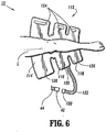
- Sleeve 112 includes a thigh bladder 114, a calf bladder 116 and an ankle bladder 118.
- Sleeve 112 includes a connector 120 that mates with mating connector 42, which is connected to port 38 via tubing 44.
- Connector 120 fluidly communicates with the chambers of sleeve 112 via tubing set 122.
- connector 120 may further include a valve mechanism to control fluid flow.
- Sleeve 112 is provided and manipulated for disposal about leg L of the subject (not shown).
- Connector 120 is mated with mating connector 42 to establish fluid communication between sleeve 112 and the pneumatic circuit.
- Sleeve 112 is wrapped about leg L and secured thereto via hook and loop pads 124, 126.
- compression treatment system 10 may treat a second leg of a subject with a compression sleeve, similar to sleeve 112, via connection to port 40. The second leg is treated in compression cycles alternate to the compression cycles described below for treatment of leg L, as described below in the alternative.
- housing 12 and controller 14, described above, provide a compression treatment system 10 that facilitates transport and subject mobility.
- This advantageous configuration provides uninterrupted DVT prophylaxis as the system is used throughout a treatment facility, and can be worn and used continuously by the subject during the entire period of risk.
- Compression treatment system 10 advantageously facilitates continuous vascular therapy during subject activity and tasks such as, for example, transport for testing, bathroom, physical therapy, etc.
- Compression treatment system 10 prevents interruptions in therapy by providing controller 14 that will run on battery 28 when power cord 26 is not plugged in, and will also be comfortable, compact, and light enough to move with the subject as needed.
- control panel 32 of controller 14 switch compression treatment system 10 on for powering thereof.
- compression treatment system 10 is initially switched on, a series of self-tests are conducted by the control processor of controller 14.
- the LED indicators of display 36 are illuminated and audible indicia are sounded to verify the operability of the visual and audible indicators.
- Display 36 is illuminated to verify display operability.
- Controller 14 also verifies operability of the software of the control processor. If any of the verification fails, error codes provide a representative audible and/or visual indicia.
- controller 14 Upon completion of the self-test sequence compression for treatment system 10, controller 14 begins a sleeve detection procedure to determine the type(s) of sleeves attached to ports 38, 40.
- Sleeve detection is performed during a first inflation (detection) cycle after controller 14 is initially powered on. During the detection cycle, air is delivered alternately through ports 38, 40 with pump 50 operating for two seconds, or until the pressure reaches a default threshold.
- pressure transducer 66 takes a pressure measurement to determine whether or not a bladder is connected to a particular output port, 38 a , 38 b , 38 c , 40 a, 40 b or 40 c under sleeve detection.
- the detection procedure is conducted for bladders 114, 116, 118 for each of sleeve ports 38,40. If there is no backpressure at a particular outlet port for connection with a bladder, then the control processor of controller 14 determines that a bladder is not being used with a particular outlet port. The control processor adjusts the compression therapy for the detected sleeve configuration accordingly. For the 3-bladder sleeve, back pressure is detected at bladders 114, 116, 118 when connected to controller 14. It is contemplated that if no sleeves are detected by this procedure at either port 38 or 40, or if the detected configuration is not recognized, then a low pressure error is triggered with corresponding audible indicia. It is further contemplated that various timing periods may be employed for detection inflation and pressure measurement, according to the requirements of a particular application.
- thigh bladder 114 is removable from calf bladder 116.
- calf bladder 116 is removably connected to thigh bladder 114 via a perforated attachment, see, for example, the sleeve described in U.S. Patent Application Serial No. 10/784,607, filed on February 23, 2004 and entitled Compression Apparatus.
- the control processor of controller 14 performs a similar sleeve detection procedure, as described above.
- the control processor will detect a 3-bladder sleeve due to a flow-restricting valve (not shown) fitted with connector 120. See, for example, the flow-restricting valve described in U.S. Patent Application Serial No.
- the flow restricting valve simulates the backpressure created by thigh bladder 114 when there is actually no bladder connected.
- controller 14 continues vascular therapy as if thigh bladder 114 was still intact.
- sleeve 112 includes thigh bladder 114 and a unitary second bladder 218.
- Second bladder 218 has a calf portion 220 and an ankle portion 222.
- Pump 50 fluidly communicates with sleeve 112 via valve connector 224 and separate tubing 226, 228, for employment similar to that described above, including the optional removal of thigh bladder 114 via perforations or the like.
- the compression parameters include an 11-second inflation period for inflating bladders 114, 116, 118 followed by 60 seconds of venting for deflating bladders 114, 116, 118.
- the 11-second inflation period is sequential:
- vent period is measured from the end of one inflation cycle to the beginning of the next inflation cycle on leg L. It is further contemplated that both limbs of the subject may be treated and compression treatment system 10 alternates vascular therapy from leg L to the second leg. It is envisioned that the time period from the end of the inflation cycle for leg L to the initiation of the inflation cycle for the second leg can range, for example, from 4.5-24.5 seconds.
- pump 50 initiates a low default voltage so as to not over-inflate bladders 114, 116, 118 on the initial cycle.
- Solenoid valves 58 a , 58 b , 58 c are energized to the open position, as described, such that the valves open to deliver air to ankle bladders 118, then calf bladder 116, then thigh bladder 114 of sleeve 112 using a desired cycle timing sequence.
- Pressure transducer 66 monitors the pressure in each of bladders 114, 116, 118 throughout the 11-second compression cycle.
- pump 50 stops and solenoid valves 58 a , 58 b , 58 c de-energize to the closed position to allow bladders 114, 116, 118 to deflate through vent ports 66 a, 66 b, 66 c .
- solenoid valves 60 a , 60 b , 60 c are energized to the open position, as described, such that the valves open to deliver air to corresponding bladders of a sleeve disposed about the second leg, similar to sleeve 112, using a desired cycle timing sequence.
- Pressure transducer 66 monitors the pressure in each of the corresponding bladders throughout the 11-second compression cycle.
- pump 50 stops and solenoid valves 60 a , 60 b , 60 c de-energize to the closed position to allow the corresponding bladders to deflate through vent ports 68 a , 68 b , 68 c .
- the inflation cycle for treatment of the second leg may be initiated approximately 24.5 seconds after completion of the inflation cycle for treating leg L. This process may be reiterated for cycles pertaining to both legs. Other cycle times are contemplated.
- the pressures, as measured by pressure transducer 66 and the corresponding signal relayed to the control processor of controller 14, of bladders 114, 116, 118 during the inflation cycle remain gradient with the pressure of ankle bladder 118 being greater than the pressure of calf bladder 116, and the pressure of calf bladder 116 being greater than the pressure of thigh bladder 114.
- the end of cycle pressures for example, include 45 mm Hg in ankle bladder 118, 40 mm Hg in calf bladder 116, and 30 mm Hg in thigh bladder 114.
- Table 2 An example is illustrated in Table 2 below. It is contemplated that compression continues in this cyclical pattern until either compression treatment system 10 is turned off or controller 14 indicates and error code via audible or visual indicia.
- a pressure feedback adjustment can be made pursuant to the pressure measurement taken by pressure transducer 66.
- the end of cycle pressure in ankle bladder 118 is measured by pressure transducer 66 and compared by the control processor of controller 14 with the set pressure of 45 mm Hg. If the pressure of ankle bladder 118 is higher or lower than the set pressure, then a corresponding decrease or increase in the speed of pump 50 is required to decrease or increase pressure delivery.
- , where P pressure at the ankle
- compression treatment system 10 may adjust for separate pump speeds for each sleeve connected to controller 14. Other sequential compression cycles are also contemplated.
- VRT Venous refill time
- compression treatment system 10 performs venous refill time measurement.
- Venous refill time (VRT) measurement is an air plethysmographic technique that determines when the veins of a limb have completely refilled with blood following a compression cycle. See, for example, the venous refill time measurement described in U.S. Patent No. 6,231,532 to Watson et al.
- the VRT minimizes the amount of time that the blood remains stagnant inside the veins.
- the VRT will be substituted for the default rest time (60 seconds) as long as the VRT is between 20 and 60 seconds. If the VRT is less than 20 seconds then the default of 20 seconds is used. If the VRT is greater than 60 seconds then the maximum of 60 seconds is used.
- the VRT measurement is made when the system first reaches set pressure and once every 30 minutes thereafter. It is contemplated that the VRT technique and algorithm can be used for both sleeve and foot compression.
- the VRT measurement uses an air plethysmographic technique where a low pressure is applied to the calf bladders. As the veins fill with blood, the pressures in the calf bladders increase until a plateau is reached. The time that it takes for the pressure to plateau is the VRT. If two sleeves are connected to controller 14, then the VRT is determined separately for each limb being compressed and the greater of the two measurements is used as the new vent time of the compression cycle. The VRT measurement for each sleeve is made as each particular sleeve reaches set pressure independently. However, the vent time is not updated until VRT measurements have been calculated for both sleeves.
- compression treatment system 10 may employ the VRT measurement after the system initiates vascular therapy. Subsequently, after 30 minutes have elapsed, a VRT measurement will be taken on the next full inflation cycle. After any of the sleeves described above inflates, the bladder(s) of the particular sleeve are vented down to zero as in the default inflation cycle.
- a selected bladder pressure is monitored and the vent to the bladder is closed when the pressure falls to 5-7 mm Hg. If the pressure in the bladder is 5-7 mm Hg on a current cycle then a VRT measurement is taken. If the pressure in the bladder does not vent down to 5-7 mm Hg then the vent time will remain at its current value and another measurement will be made in 30 minutes. If an error occurs, a corresponding alarm provides audible and/or visual indicia.
- the VRT measurement algorithm determines when the pressures in the selected bladders plateau after compression. The VRT will be determined separately for both legs. The longer of the two refill times will be used as the new vent time. If compression is applied to only one leg, the VRT for that leg is used as the new vent time.
- the VRT measurement algorithm initiates with a time counter started from the end of the inflation cycle, which occurs after the selected bladder reaches 5-7 mm Hg (enough pressure to cause the bladder to remain in contact with the surface of the leg) and the venting is stopped. The VRT measurement initiates with the time counter started from the end of the inflation cycle.
- the pressure in the selected bladder is then monitored.
- the pressure is monitored with a 10-second, moving sample window.
- the window moves in 1-second intervals.
- the difference between the first and last values in the window is less than approximately 0.3 mm Hg the curve has reached its plateau.
- the VRT measurement is considered done, and the time interval is determined.
- the end of the window is considered to be the point at which the venous system in the limbs has refilled.
- the selected bladder is allowed to vent for at least 15 seconds before the next compression cycle on that same limb is started.
- 5 seconds are added to the measured refill time so the limb is not compressed too early.
- the vent time may be equivalent to the measured refill time plus 5 seconds.
- the standard deviation in the sample window may be too high making the measurement erroneous.
- the calculation is discarded and the old value of the VRT is used.
- the VRT measurement is considered erroneous if at any time during the measurement, the pressure in the selected bladder is below 2 mmHg, the calculation is discarded, and the old value of VRT is used.
- VRT pressure is greater than 20 mmHg at any time during the VRT measurement the old value of the VRT is used. It is further contemplated that if the VRT calculation is done for both legs, the longer VRT of both legs is used. It is envisioned that if the VRT is calculated to be greater than 60 seconds, a value of 60 seconds is used. If the VRT is calculated to be less than 20 seconds, a value of 20 seconds is used.
- compression treatment system 10 may employ one, a plurality or all of the following error codes to provide audible and/or visual indicia of system error or failure. These features advantageously enhance safety to the subject during vascular therapy. Several error conditions may cause compression treatment system 10 to provide alarm and stop a particular compression cycle. It is contemplated that compression treatment system 10 may flash error indicators, sound continuous signals, etc., causing a user to reset compression treatment system 10.
- Controller 14 may provide an error alarm for one, a plurality or all of the following error conditions: high pressure error, including those pressures detected in excess of set pressure; low pressure error, including those pressures detected below set pressure and if no sleeves are detected; system pressure error, including pressure determined within an inflation cycle outside of desired parameters; valve error; software error; pump error; vent and deflation error; battery error; and temperature error, including temperatures detected outside of specified environmental conditions.
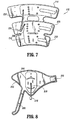
- compression treatment system 10 in an alternate example not covered by the claims, as shown in FIG. 8 , compression treatment system 10, similar to that described above, includes a foot sleeve 312 configured to provide vascular therapy to the foot of the subject.
- Foot sleeve 312 includes a bladder 314 that is inflated with air to provide application of pressure to the foot and then deflated. See, for example, the sleeve described in U.S. Patent Application Serial No. 10/784,604, filed on February 23, 2004 and entitled Compression Apparatus.
- Sleeve 312 includes a connector 316 that mates with mating connector 42, which is connected to port 40 via tubing 44.
- Valve connector 316 fluidly communicates with bladder 314 of sleeve 312 via tubing 318.
- this configuration facilitates fluid communication between bladder 314 and pump 50.
- Foot sleeve 312 wraps about the side portions of the foot via a hook and loop type connector flap 320 that transverses the instep of the foot and a hook and loop type connector ankle strap 322.
- controller 14 Upon completion of the self-test sequence compression for treatment system 10, similar to that described, controller 14 begins the sleeve detection procedure to determine the type(s) of sleeves attached to ports 38, 40. With regard to foot sleeve 312, back pressure is detected by the control processor of controller 14 corresponding to bladder 314, which is connected to outlet port 40 b . It is contemplated that compression treatment system 10 may treat the foot of a second leg of a subject with foot sleeve 312 and also treat leg L, as described above, in alternate inflation cycles.
- the compression parameters include a 5-second inflation period followed by 60 seconds of venting.
- An example is illustrated in Table 3 below.
- Table 3 Start of Sequence End of Sequence Foot Compression: 0 Seconds 5.0 seconds
- Decompression/Vent Minimum 20 seconds,maximum 60 seconds
- vent period is measured from the end of one inflation cycle to the beginning of the next inflation cycle on the foot of the subject. It is further contemplated that both limbs of the subject may be treated and compression treatment system 10 alternates vascular therapy from leg L to the second leg. It is envisioned that the time period from the end of the inflation cycle for leg L to the initiation of the inflation cycle for the second leg can range from 7.5-27.5 seconds.
- pump 50 initiates a low default voltage so as to not over-inflate bladder 314 on the initial cycle.
- Solenoid valve 60 b is energized to the open position, as described, such that the valve opens to deliver air to bladder 314 using a desired cycle timing sequence.
- Pressure transducer 66 monitors the pressure in bladder 314 throughout the 5-second compression cycle.
- pump 50 stops and solenoid valve 60 b de-energizes to the closed position to allow bladder 314 to deflate through vent port 68 b .
- solenoid valve 58 b is energized to the open position, as described, such that the valve opens to deliver air to a corresponding bladder of a foot sleeve disposed about the other leg, similar to foot sleeve 312, using a desired cycle timing sequence.
- pressure transducer 66 monitors the pressure in the corresponding bladder throughout the 5-second compression cycle.
- pump 50 stops and solenoid valve 58 b de-energizes to the closed position to allow the corresponding bladder to deflate through vent port 66 b .
- the inflation cycle for treatment of the second foot may be initiated approximately 27.5 seconds after completion of the inflation cycle for treating the foot treated by foot sleeve 312. This process may be reiterated for cycles pertaining to both feet, or in the alternative, for foot sleeve of a first leg and a leg sleeve of a second leg. It is contemplated that compression treatment system 10 may provide alternating compression to any combination of a sleeve and a foot garment and that if such a combination is employed, then, for example, a 6-second buffer of additional vent timing is added to all vent periods after the foot inflation cycle so that the overall timing is consistent with the default sleeve compression parameters. Other cycle times are contemplated.
- the target pressure, as measured by pressure transducer 66 and the corresponding signal relayed to the control processor of controller 14, of bladder 314 is, for example, 130 mm Hg. It is contemplated that compression continues in this cyclical pattern until either compression treatment system 10 is turned off or controller 14 indicates an error code via audible or visual indicia.
- a pressure feedback adjustment can be made pursuant to the pressure measurement taken by pressure transducer 66.
- the end of cycle pressure in bladder 314 is measured by pressure transducer 66 and compared by the control processor of controller 14 with the set pressure of 130 mm Hg. If the pressure of bladder 314 is higher or lower than the set pressure, then a corresponding decrease or increase in the speed of pump 50 is required to decrease or increase pressure delivery.
- compression treatment system 10 may adjust for separate pump speeds for each sleeve connected to controller 14. Other sequential compression cycles are also contemplated.
Landscapes
- Health & Medical Sciences (AREA)
- Epidemiology (AREA)
- Pain & Pain Management (AREA)
- Physical Education & Sports Medicine (AREA)
- Rehabilitation Therapy (AREA)
- Life Sciences & Earth Sciences (AREA)
- Animal Behavior & Ethology (AREA)
- General Health & Medical Sciences (AREA)
- Public Health (AREA)
- Veterinary Medicine (AREA)
- Massaging Devices (AREA)
- Infusion, Injection, And Reservoir Apparatuses (AREA)
- Surgical Instruments (AREA)
- Separation By Low-Temperature Treatments (AREA)
- Electron Tubes For Measurement (AREA)
- Nonmetallic Welding Materials (AREA)
- Orthopedics, Nursing, And Contraception (AREA)
- Finger-Pressure Massage (AREA)
- Loading And Unloading Of Fuel Tanks Or Ships (AREA)
- Medicines That Contain Protein Lipid Enzymes And Other Medicines (AREA)
- Tea And Coffee (AREA)
- Polarising Elements (AREA)
- Superconductors And Manufacturing Methods Therefor (AREA)
- Pharmaceuticals Containing Other Organic And Inorganic Compounds (AREA)
- Fluid-Pressure Circuits (AREA)
- Quick-Acting Or Multi-Walled Pipe Joints (AREA)
- Accessory Devices And Overall Control Thereof (AREA)
- Prostheses (AREA)
- Non-Positive Displacement Air Blowers (AREA)
Claims (3)
- Kompressionsbehandlungssystem (10), umfassend:eine Pumpe (50) als eine Fluidquelle;eine Hülse (46, 48), welche mehrere Balgen (46a, 46b, 46c, 48a, 48b, 48c) umfasst, welche ausgebildet sind, um um ein Körperglied gehaltert zu sein und welche mit der Fluidquelle fluidisch kommunizieren;ein Gehäuse (12), welches ein Bedienpult (32), Anschlüsse (38, 40) und die Pumpe umfasst,Magnetventile (58, 60), welche mit der Pumpe (50) zum selektiven Durchlassen oder Sperren einer Fluidströmung von der Pumpe (50) zu den Balgen fluidisch kommunizieren;einen Druckgeber (66);einen Pneumatikkreis, um das Aufblasen der Balgen (46a, 46b, 46c, 48a, 48b, 48c) zu ermöglichen und eine Drucküberwachung, welche den Druckgeber (66) verwendet, wobeider Druckgeber (66) mit dem Pneumatikkreis gekoppelt ist und zwischen der Pumpe (50) und den Magnetventilen (58a, 58b, 58c, 60a, 60b, 60c) mittels Leitungen angeordnet ist;gekennzeichnet durcheinen Steuerprozessor im Gehäuse (12), welcher mit dem Bedienpult (32), mit der Pumpe (50) und mit den Magnetventilen (58, 60) zur Steuerung des Betriebs der Pumpe (50) und der Magnetventile (58, 60) kommuniziert, wobei der Steuerprozessor programmiert ist, um eine Hülsendetektionsprozedur während eines ersten Aufblaszyklus auszuführen, nachdem der Steuerprozessor (14) anfänglich eingeschaltet wird und beim Abschließen einer Selbsttest-Sequenz, wobei die Hülsendetektionsprozedur die folgenden Schritte umfasst:(a) Zuführen von Luft durch die Anschlüsse (38, 40), mit der Pumpe (50), bis der Druck eine Standardschwelle erreicht;(b) Ausführen einer Druckmessung mit dem Druckgeber (66), um zu bestimmen, ob ein Balg (46, 48) mit einem besonderen Anschluss (38a, 38b, 38c, 40a, 40b, 40c) während der Hülsendetektion verbunden ist;(c) Bestimmen, dass ein Balg (46a, 46b, 46c, 48a, 48b, 48c) nicht mit einem besonderen Anschluss (38a, 38b, 38c, 40a, 40b, 40c) verbunden ist, wenn kein Gegendruck vorhanden ist;(d) Detektieren der Anschlüsse, welche verbunden sind, und Bestimmen des Typs der verbundenen Hülse (46, 48), und(e) Einstellen der entsprechenden geeigneten Kompressionsbehandlung.
- Kompressionsbehandlungssystem nach Anspruch 1,
dadurch gekennzeichnet, dass der Typ der Hülse (46, 48) eine Beinhülse oder eine Fußmanschette ist. - Kompressionsbehandlungssystem nach Anspruch 1 oder 2,
dadurch gekennzeichnet, dass
der Steuerprozessor einen weiteren Schritt des Aktivierens eines Niedrigdruckfehlers mit entsprechenden hörbaren Zeichen ausführt, falls keine Hülsen (46, 48) an den Anschlüssen (38, 40) detektiert werden oder falls der detektierte Typ nicht erkannt wird.
Applications Claiming Priority (6)
| Application Number | Priority Date | Filing Date | Title |
|---|---|---|---|
| US10/784,604 US7282038B2 (en) | 2004-02-23 | 2004-02-23 | Compression apparatus |
| US10/784,607 US7871387B2 (en) | 2004-02-23 | 2004-02-23 | Compression sleeve convertible in length |
| US10/784,323 US7354410B2 (en) | 2004-02-23 | 2004-02-23 | Compression treatment system |
| US10/784,639 US7490620B2 (en) | 2004-02-23 | 2004-02-23 | Fluid conduit connector apparatus |
| PCT/US2005/005598 WO2005082314A1 (en) | 2004-02-23 | 2005-02-23 | Compression treatment system |
| EP05713933.9A EP1722738B1 (de) | 2004-02-23 | 2005-02-23 | Kompressionsbehandlungssystem |
Related Parent Applications (2)
| Application Number | Title | Priority Date | Filing Date |
|---|---|---|---|
| EP05713933.9 Division | 2005-02-23 | ||
| EP05713933.9A Division EP1722738B1 (de) | 2004-02-23 | 2005-02-23 | Kompressionsbehandlungssystem |
Publications (3)
| Publication Number | Publication Date |
|---|---|
| EP2314268A2 EP2314268A2 (de) | 2011-04-27 |
| EP2314268A3 EP2314268A3 (de) | 2014-06-18 |
| EP2314268B1 true EP2314268B1 (de) | 2020-04-22 |
Family
ID=34916527
Family Applications (6)
| Application Number | Title | Priority Date | Filing Date |
|---|---|---|---|
| EP05723526A Expired - Lifetime EP1720505B1 (de) | 2004-02-23 | 2005-02-23 | Kompressionsgerät |
| EP05713934A Expired - Lifetime EP1718894B1 (de) | 2004-02-23 | 2005-02-23 | Fluidleitungsverbindervorrichtung |
| EP05713933.9A Expired - Lifetime EP1722738B1 (de) | 2004-02-23 | 2005-02-23 | Kompressionsbehandlungssystem |
| EP10185262.2A Withdrawn EP2319476A3 (de) | 2004-02-23 | 2005-02-23 | Kompressionsbehandlungssystem |
| EP10185260.6A Expired - Lifetime EP2314268B1 (de) | 2004-02-23 | 2005-02-23 | Kompressionsbehandlungssystem |
| EP05713935A Expired - Lifetime EP1720504B1 (de) | 2004-02-23 | 2005-02-23 | Kompressionsgerät |
Family Applications Before (4)
| Application Number | Title | Priority Date | Filing Date |
|---|---|---|---|
| EP05723526A Expired - Lifetime EP1720505B1 (de) | 2004-02-23 | 2005-02-23 | Kompressionsgerät |
| EP05713934A Expired - Lifetime EP1718894B1 (de) | 2004-02-23 | 2005-02-23 | Fluidleitungsverbindervorrichtung |
| EP05713933.9A Expired - Lifetime EP1722738B1 (de) | 2004-02-23 | 2005-02-23 | Kompressionsbehandlungssystem |
| EP10185262.2A Withdrawn EP2319476A3 (de) | 2004-02-23 | 2005-02-23 | Kompressionsbehandlungssystem |
Family Applications After (1)
| Application Number | Title | Priority Date | Filing Date |
|---|---|---|---|
| EP05713935A Expired - Lifetime EP1720504B1 (de) | 2004-02-23 | 2005-02-23 | Kompressionsgerät |
Country Status (14)
| Country | Link |
|---|---|
| EP (6) | EP1720505B1 (de) |
| JP (4) | JP4602996B2 (de) |
| KR (5) | KR100914569B1 (de) |
| CN (1) | CN102614074B (de) |
| AT (3) | ATE536851T1 (de) |
| AU (4) | AU2005216924B2 (de) |
| CA (4) | CA2552354C (de) |
| DE (2) | DE602005021460D1 (de) |
| DK (1) | DK1720504T3 (de) |
| ES (4) | ES2806930T3 (de) |
| IL (4) | IL176410A (de) |
| NO (4) | NO20064256L (de) |
| PL (2) | PL1720504T3 (de) |
| WO (4) | WO2005083313A1 (de) |
Families Citing this family (68)
| Publication number | Priority date | Publication date | Assignee | Title |
|---|---|---|---|---|
| GB0515294D0 (en) | 2005-07-26 | 2005-08-31 | Novamedix Distrib Ltd | Limited durability closure means for an inflatable medical garment |
| GB0523249D0 (en) * | 2005-11-15 | 2005-12-21 | Huntleigh Technology Plc | Identification means |
| US8029451B2 (en) | 2005-12-12 | 2011-10-04 | Tyco Healthcare Group Lp | Compression sleeve having air conduits |
| GB0601453D0 (en) * | 2006-01-24 | 2006-03-08 | Bristol Myers Squibb Co | Pressurised medical device |
| JP4710758B2 (ja) | 2006-08-28 | 2011-06-29 | パナソニック電工株式会社 | マッサージ機 |
| GB0622415D0 (en) | 2006-11-10 | 2006-12-20 | Huntleigh Technology Plc | Compression system |
| US8029450B2 (en) | 2007-04-09 | 2011-10-04 | Tyco Healthcare Group Lp | Breathable compression device |
| US8506508B2 (en) | 2007-04-09 | 2013-08-13 | Covidien Lp | Compression device having weld seam moisture transfer |
| US8109892B2 (en) | 2007-04-09 | 2012-02-07 | Tyco Healthcare Group Lp | Methods of making compression device with improved evaporation |
| US8034007B2 (en) | 2007-04-09 | 2011-10-11 | Tyco Healthcare Group Lp | Compression device with structural support features |
| US8162861B2 (en) | 2007-04-09 | 2012-04-24 | Tyco Healthcare Group Lp | Compression device with strategic weld construction |
| US8016779B2 (en) | 2007-04-09 | 2011-09-13 | Tyco Healthcare Group Lp | Compression device having cooling capability |
| US8070699B2 (en) | 2007-04-09 | 2011-12-06 | Tyco Healthcare Group Lp | Method of making compression sleeve with structural support features |
| US8016778B2 (en) | 2007-04-09 | 2011-09-13 | Tyco Healthcare Group Lp | Compression device with improved moisture evaporation |
| US8128584B2 (en) | 2007-04-09 | 2012-03-06 | Tyco Healthcare Group Lp | Compression device with S-shaped bladder |
| US8021388B2 (en) | 2007-04-09 | 2011-09-20 | Tyco Healthcare Group Lp | Compression device with improved moisture evaporation |
| US8182437B2 (en) | 2007-05-08 | 2012-05-22 | Wright Therapy Products, Inc. | Pneumatic compression therapy system and methods of using same |
| US8388557B2 (en) | 2007-06-20 | 2013-03-05 | Remo Moomiaie-Qajar | Portable compression device |
| GB0712764D0 (en) | 2007-07-02 | 2007-08-08 | Smith & Nephew | Carrying Bag |
| US8246028B2 (en) | 2007-11-08 | 2012-08-21 | Tyco Healthcare Group Lp | Telescopingly adjustable clamp |
| US8114117B2 (en) | 2008-09-30 | 2012-02-14 | Tyco Healthcare Group Lp | Compression device with wear area |
| US8235923B2 (en) | 2008-09-30 | 2012-08-07 | Tyco Healthcare Group Lp | Compression device with removable portion |
| US8133039B2 (en) | 2009-01-26 | 2012-03-13 | Tyco Healthcare Group Lp | Mount for a compression control unit |
| US8419666B2 (en) * | 2009-09-23 | 2013-04-16 | Caremed Supply, Inc. | Compression sleeve |
| US8506507B2 (en) * | 2010-03-09 | 2013-08-13 | Covidien Lp | Venous augmentation system |
| US8652079B2 (en) | 2010-04-02 | 2014-02-18 | Covidien Lp | Compression garment having an extension |
| USD659839S1 (en) | 2010-08-16 | 2012-05-15 | Tyco Healthcare Group Lp | Support for a pneumatic compression controller |
| USD675741S1 (en) | 2010-08-16 | 2013-02-05 | Covidien Lp | Pneumatic compression controller |
| US10751221B2 (en) | 2010-09-14 | 2020-08-25 | Kpr U.S., Llc | Compression sleeve with improved position retention |
| US8398572B2 (en) * | 2010-09-21 | 2013-03-19 | Covidien Lp | Bladder tube connection |
| US8758282B2 (en) | 2010-09-29 | 2014-06-24 | Covidien Lp | Compression garment apparatus having support bladder |
| US8753300B2 (en) * | 2010-09-29 | 2014-06-17 | Covidien Lp | Compression garment apparatus having baseline pressure |
| CA2778395A1 (en) * | 2011-06-10 | 2012-12-10 | Tyco Healthcare Group Lp | Compression device having a pause feature |
| US10828402B2 (en) * | 2011-10-14 | 2020-11-10 | Alcon Inc. | Collar connector |
| JP6392744B2 (ja) | 2012-03-12 | 2018-09-19 | ライト セラピー プロダクツ、インク. | 複数の同時活性化チャンバーを有する圧縮療法装置 |
| US9889063B2 (en) | 2012-06-11 | 2018-02-13 | Wright Therapy Products, Inc. | Methods and systems for determining use compliance of a compression therapy device |
| US9205021B2 (en) | 2012-06-18 | 2015-12-08 | Covidien Lp | Compression system with vent cooling feature |
| SG11201500759PA (en) * | 2012-07-30 | 2015-03-30 | Univ Kochi Nat Univ Corp | In vivo acetylcholine production-promoting device |
| WO2014031409A1 (en) | 2012-08-18 | 2014-02-27 | Wright Therapy Products, Inc. | Methods for determining the size of body parts as part of compression therapy procedures |
| US9872812B2 (en) | 2012-09-28 | 2018-01-23 | Kpr U.S., Llc | Residual pressure control in a compression device |
| USD764654S1 (en) | 2014-03-13 | 2016-08-23 | Smith & Nephew, Inc. | Canister for collecting wound exudate |
| US9295605B2 (en) | 2013-12-02 | 2016-03-29 | Wright Therapy Products, Inc. | Methods and systems for auto-calibration of a pneumatic compression device |
| US10470967B2 (en) | 2014-01-20 | 2019-11-12 | Tactile Systems Technology, Inc. | Bespoke compression therapy device |
| US10292894B2 (en) | 2014-02-11 | 2019-05-21 | Tactile Systems Technology, Inc. | Compression therapy device and compression therapy protocols |
| USD764047S1 (en) | 2014-05-28 | 2016-08-16 | Smith & Nephew, Inc. | Therapy unit assembly |
| USD764048S1 (en) | 2014-05-28 | 2016-08-16 | Smith & Nephew, Inc. | Device for applying negative pressure to a wound |
| USD764653S1 (en) | 2014-05-28 | 2016-08-23 | Smith & Nephew, Inc. | Canister for collecting wound exudate |
| USD770173S1 (en) | 2014-06-02 | 2016-11-01 | Smith & Nephew, Inc. | Bag |
| USD765830S1 (en) | 2014-06-02 | 2016-09-06 | Smith & Nephew, Inc. | Therapy unit assembly |
| US10071011B2 (en) * | 2014-06-30 | 2018-09-11 | Kpr U.S., Llc | Compression garment inflation |
| KR20170046718A (ko) | 2014-08-27 | 2017-05-02 | 코비디엔 엘피 | 압박 의류 팽창 |
| JP6787903B2 (ja) | 2015-01-27 | 2020-11-18 | メディヴァンス インコーポレイテッドMedivance,Inc. | 熱療法用の改良された医療用パッド及びシステム |
| DE102015105371A1 (de) * | 2015-04-09 | 2016-10-13 | Kongsberg Automotive Ab | Massagevorrichtung für einen Fahrzeugsitz |
| US10166164B2 (en) | 2016-04-27 | 2019-01-01 | Radial Medical, Inc. | Adaptive compression therapy systems and methods |
| JP2019519284A (ja) * | 2016-05-26 | 2019-07-11 | ハントレイ テクノロジー リミテッドHuntleigh Technology Limited | 圧迫療法システム及び方法 |
| WO2018230930A1 (ko) * | 2017-06-16 | 2018-12-20 | 주식회사 뷰엘리스 | 공기압 마사지용 다리커프 |
| US11504927B2 (en) | 2018-03-23 | 2022-11-22 | TurnCare, Inc. | Systems and methods for controlling and monitoring inflatable perfusion enhancement apparatus for mitigating contact pressure |
| KR102810389B1 (ko) | 2018-03-23 | 2025-05-21 | 턴케어, 인코포레이티드 | 팽창가능한 관류 향상 장치 및 그 관련 장치, 시스템 및 방법 |
| JP6813531B2 (ja) * | 2018-05-16 | 2021-01-13 | 日東工器株式会社 | 空気圧式のマッサージ装置及びその空気供給チューブ |
| US10893998B2 (en) | 2018-10-10 | 2021-01-19 | Inova Labs Inc. | Compression apparatus and systems for circulatory disorders |
| BR112022023393A2 (pt) | 2020-05-22 | 2022-12-27 | Kpr Us Llc | Sistema, método e dispositivo que utiliza conector reversível |
| KR20220019182A (ko) | 2020-08-07 | 2022-02-16 | 유인종 | 하지 정맥류 치료장치용 압박 스타킹에 사용되는 공기압 조절 장치 및 이를 포함하는 하지 정맥류 치료장치 |
| KR20220019180A (ko) | 2020-08-07 | 2022-02-16 | 유인종 | 하지 정맥류 치료장치용 압박 스타킹 및 그 제조방법, 그리고 이를 포함하는 하지 정맥류 치료장치 |
| US12496215B2 (en) | 2021-01-25 | 2025-12-16 | C. R. Bard, Inc. | Transparent pad |
| US12433785B2 (en) | 2021-02-23 | 2025-10-07 | C. R. Bard, Inc. | Gel pad assembly using free rotatable fluid joints |
| US12241570B2 (en) | 2021-07-07 | 2025-03-04 | C. R. Bard, Inc. | Negative pressure connector seal |
| JP7283816B1 (ja) * | 2022-02-17 | 2023-05-30 | 株式会社テクノ高槻 | 給排気装置 |
| USD1099288S1 (en) | 2022-03-23 | 2025-10-21 | T.J. Smith And Nephew, Limited | Device for applying negative pressure to a wound |
Family Cites Families (47)
| Publication number | Priority date | Publication date | Assignee | Title |
|---|---|---|---|---|
| US1883240A (en) * | 1925-11-27 | 1932-10-18 | Honeywell Regulator Co | Magnetically operated valve |
| US1608239A (en) | 1925-12-09 | 1926-11-23 | Rosett Joshua | Therapeutic device |
| US2628850A (en) * | 1949-03-19 | 1953-02-17 | Donald V Summerville | Releasable conduit connection with automatic valving |
| US4013069A (en) * | 1975-10-28 | 1977-03-22 | The Kendall Company | Sequential intermittent compression device |
| US4091804A (en) * | 1976-12-10 | 1978-05-30 | The Kendall Company | Compression sleeve |
| US4355632A (en) * | 1980-08-06 | 1982-10-26 | Jobst Institute, Inc. | Anti-shock pressure garment |
| US4374518A (en) * | 1980-10-09 | 1983-02-22 | Raul Villanueva | Electronic device for pneumomassage to reduce lymphedema |
| JPS5942030Y2 (ja) * | 1980-12-23 | 1984-12-06 | 株式会社日器 | 空圧式マツサ−ジ器用圧迫袋 |
| IL63574A (en) * | 1981-08-14 | 1985-07-31 | Mego Afek | Massaging sleeve for body limbs |
| JPS5892926U (ja) * | 1981-12-17 | 1983-06-23 | 日東工器株式会社 | 空圧マツサ−ジ器の圧縮空気供給装置 |
| US4624248A (en) * | 1983-02-07 | 1986-11-25 | David Clark Company Incorporated | Transparent pressure garment |
| US4696289C1 (en) * | 1983-06-22 | 2002-09-03 | Novamedix Distrib Ltd | Method of stimulating the venous-pump mechanism of the foot and for enhancement of arterial flow to the foot |
| US5989204A (en) * | 1991-09-27 | 1999-11-23 | Kinetic Concepts, Inc. | Foot-mounted venous compression device |
| US5186163A (en) * | 1991-11-25 | 1993-02-16 | The Kendall Company | Compression device |
| AU696794B2 (en) * | 1991-12-17 | 1998-09-17 | Covidien Ag | Pneumatic compression device and methods for use in the medical field |
| GB2295458B (en) * | 1992-09-15 | 1996-08-14 | Huntleigh Technology Plc | DVT prevention apparatus and method |
| JPH06245949A (ja) * | 1993-02-22 | 1994-09-06 | Hokoku Kogyo Co Ltd | 温冷マッサージ治療装置 |
| US5354260A (en) * | 1993-05-13 | 1994-10-11 | Novamedix, Ltd. | Slipper with an inflatable foot pump |
| US5443440A (en) * | 1993-06-11 | 1995-08-22 | Ndm Acquisition Corp. | Medical pumping apparatus |
| US5478119A (en) * | 1993-09-16 | 1995-12-26 | The Kendall Company | Polarized manifold connection device |
| US5795312A (en) * | 1993-09-27 | 1998-08-18 | The Kendall Company | Compression sleeve |
| US5575762A (en) * | 1994-04-05 | 1996-11-19 | Beiersdorf-Jobst, Inc. | Gradient sequential compression system and method for reducing the occurrence of deep vein thrombosis |
| US5591200A (en) * | 1994-06-17 | 1997-01-07 | World, Inc. | Method and apparatus for applying pressure to a body limb for treating edema |
| CA2153375C (en) * | 1994-07-26 | 2000-09-12 | Arnold Tobler | Attachment of hook and loop fastener to a compression sleeve |
| US5876359A (en) | 1994-11-14 | 1999-03-02 | Bock; Malcolm G. | Sequential compression device controller |
| GB9507328D0 (en) * | 1995-04-08 | 1995-05-31 | Novamedix Ltd | A medical device |
| JPH09313557A (ja) * | 1996-05-31 | 1997-12-09 | Megoafeck Ind Measuring Instr | 空圧マッサージ装置 |
| IL120935A0 (en) * | 1996-06-07 | 1997-09-30 | Bibi Roni | Medical apparatus for facilitating blood circulation in the lower limbs |
| US5681339A (en) * | 1996-08-12 | 1997-10-28 | Mcewen; James A. | Apparatus and method for monitoring the patency of tubing in a pneumatic medical device |
| JP4124503B2 (ja) * | 1997-06-06 | 2008-07-23 | 株式会社アドバンス | 血行促進装置 |
| JP4059956B2 (ja) * | 1997-06-30 | 2008-03-12 | 日東工器株式会社 | 空圧式マッサージ器 |
| CA2302515A1 (en) * | 1997-08-31 | 1999-03-11 | Medical Compression Systems (D.B.N.) | Device for pressurizing limbs |
| US6494852B1 (en) | 1998-03-11 | 2002-12-17 | Medical Compression Systems (Dbn) Ltd. | Portable ambulant pneumatic compression system |
| US6007559A (en) * | 1998-06-12 | 1999-12-28 | Aci Medical | Vascular assist methods and apparatus |
| JP2002521137A (ja) * | 1998-07-30 | 2002-07-16 | メディカル ダイナミックス ユーエスエイ, エルエルシー | 周期的な治療動作を人の足に適用するための医療用デバイス |
| US6062244A (en) * | 1998-08-13 | 2000-05-16 | Aci Medical | Fluidic connector |
| DE19846922C2 (de) * | 1998-10-12 | 2003-12-11 | Manuel Fernandez | Behandlungsvorrichtung |
| JP3909789B2 (ja) * | 1998-12-28 | 2007-04-25 | 日東工器株式会社 | エアマッサージ器 |
| WO2000041667A1 (en) * | 1999-01-11 | 2000-07-20 | Family Kabushiki Kaisha | Massaging machine |
| FR2789811B1 (fr) | 1999-02-11 | 2001-05-18 | Radiall Sa | Raccord coaxial pour relier deux cartes de circuit imprime |
| US6290662B1 (en) | 1999-05-28 | 2001-09-18 | John K. Morris | Portable, self-contained apparatus for deep vein thrombosis (DVT) prophylaxis |
| US6592534B1 (en) * | 1999-12-27 | 2003-07-15 | Aircast, Inc. | Inflatable medical appliance for prevention of DVT |
| JP2001286521A (ja) * | 2000-04-10 | 2001-10-16 | Nippon Colin Co Ltd | 静脈血栓塞栓症防止装置 |
| US6558338B1 (en) * | 2000-11-20 | 2003-05-06 | Mego Afek Industrial Measuring Instruments | System for and method of applying pressure to human body |
| JP3951637B2 (ja) * | 2001-06-14 | 2007-08-01 | 松下電工株式会社 | エアーマッサージ機 |
| JP2003319988A (ja) * | 2002-05-07 | 2003-11-11 | Marutaka Co Ltd | 腕用エアマッサージ機 |
| AU2003245863A1 (en) * | 2002-07-27 | 2004-02-16 | Jwl Maskin-Og Plastfabrik A/S | Rapid coupling device and method for assembling a coupling socket |
-
2005
- 2005-02-23 JP JP2006554297A patent/JP4602996B2/ja not_active Expired - Fee Related
- 2005-02-23 AU AU2005216924A patent/AU2005216924B2/en not_active Expired
- 2005-02-23 DE DE602005021460T patent/DE602005021460D1/de not_active Expired - Lifetime
- 2005-02-23 WO PCT/US2005/005599 patent/WO2005083313A1/en not_active Ceased
- 2005-02-23 WO PCT/US2005/005600 patent/WO2005082315A1/en not_active Ceased
- 2005-02-23 KR KR1020067016796A patent/KR100914569B1/ko not_active Expired - Lifetime
- 2005-02-23 KR KR1020067016795A patent/KR100873540B1/ko not_active Expired - Lifetime
- 2005-02-23 DE DE602005022165T patent/DE602005022165D1/de not_active Expired - Lifetime
- 2005-02-23 WO PCT/US2005/005679 patent/WO2005082316A2/en not_active Ceased
- 2005-02-23 KR KR1020067016843A patent/KR20070001964A/ko not_active Ceased
- 2005-02-23 ES ES10185260T patent/ES2806930T3/es not_active Expired - Lifetime
- 2005-02-23 EP EP05723526A patent/EP1720505B1/de not_active Expired - Lifetime
- 2005-02-23 KR KR1020087023566A patent/KR100918718B1/ko not_active Expired - Lifetime
- 2005-02-23 WO PCT/US2005/005598 patent/WO2005082314A1/en not_active Ceased
- 2005-02-23 AT AT05723526T patent/ATE536851T1/de active
- 2005-02-23 EP EP05713934A patent/EP1718894B1/de not_active Expired - Lifetime
- 2005-02-23 AU AU2005217424A patent/AU2005217424B2/en not_active Ceased
- 2005-02-23 JP JP2006554310A patent/JP2007522892A/ja active Pending
- 2005-02-23 CA CA2552354A patent/CA2552354C/en not_active Expired - Fee Related
- 2005-02-23 JP JP2006554298A patent/JP4686485B2/ja not_active Expired - Fee Related
- 2005-02-23 AT AT05713934T patent/ATE473390T1/de active
- 2005-02-23 ES ES05713935T patent/ES2346546T3/es not_active Expired - Lifetime
- 2005-02-23 CA CA002552355A patent/CA2552355C/en not_active Expired - Fee Related
- 2005-02-23 EP EP05713933.9A patent/EP1722738B1/de not_active Expired - Lifetime
- 2005-02-23 CN CN201210098027.XA patent/CN102614074B/zh not_active Expired - Lifetime
- 2005-02-23 PL PL05713935T patent/PL1720504T3/pl unknown
- 2005-02-23 EP EP10185262.2A patent/EP2319476A3/de not_active Withdrawn
- 2005-02-23 KR KR1020067016842A patent/KR100868148B1/ko not_active Expired - Fee Related
- 2005-02-23 AT AT05713935T patent/ATE468834T1/de not_active IP Right Cessation
- 2005-02-23 EP EP10185260.6A patent/EP2314268B1/de not_active Expired - Lifetime
- 2005-02-23 CA CA002552331A patent/CA2552331C/en not_active Expired - Fee Related
- 2005-02-23 EP EP05713935A patent/EP1720504B1/de not_active Expired - Lifetime
- 2005-02-23 PL PL05723526T patent/PL1720505T3/pl unknown
- 2005-02-23 DK DK05713935.4T patent/DK1720504T3/da active
- 2005-02-23 ES ES05723526T patent/ES2378886T3/es not_active Expired - Lifetime
- 2005-02-23 AU AU2005216934A patent/AU2005216934B2/en not_active Ceased
- 2005-02-23 AU AU2005216923A patent/AU2005216923B2/en not_active Expired
- 2005-02-23 CA CA002552353A patent/CA2552353C/en not_active Expired - Fee Related
- 2005-02-23 ES ES05713933T patent/ES2414880T3/es not_active Expired - Lifetime
- 2005-02-23 JP JP2006554296A patent/JP4571156B2/ja not_active Expired - Lifetime
-
2006
- 2006-06-19 IL IL176410A patent/IL176410A/en active IP Right Grant
- 2006-06-19 IL IL176409A patent/IL176409A/en active IP Right Grant
- 2006-06-20 IL IL176433A patent/IL176433A/en active IP Right Grant
- 2006-06-20 IL IL176432A patent/IL176432A0/en unknown
- 2006-09-20 NO NO20064256A patent/NO20064256L/no not_active Application Discontinuation
- 2006-09-20 NO NO20064255A patent/NO20064255L/no not_active Application Discontinuation
- 2006-09-21 NO NO20064281A patent/NO20064281L/no not_active Application Discontinuation
- 2006-09-22 NO NO20064310A patent/NO20064310L/no not_active Application Discontinuation
Non-Patent Citations (1)
| Title |
|---|
| None * |
Also Published As
Similar Documents
| Publication | Publication Date | Title |
|---|---|---|
| EP1722738B1 (de) | Kompressionsbehandlungssystem | |
| US7354410B2 (en) | Compression treatment system | |
| JP4603026B2 (ja) | 圧迫装置、システム、及び使用方法 | |
| US6290662B1 (en) | Portable, self-contained apparatus for deep vein thrombosis (DVT) prophylaxis | |
| US20120209153A1 (en) | Deep vein thrombosis therapy device | |
| US20250161143A1 (en) | Rapid Cycling Compression Device for the Prevention of Thrombosis | |
| GB2612313A (en) | Intermittent pneumatic compression device | |
| WO2022045975A1 (en) | Compression apparatus | |
| HK1125820B (en) | An apparatus for preventing deep vein thrombosis |
Legal Events
| Date | Code | Title | Description |
|---|---|---|---|
| PUAI | Public reference made under article 153(3) epc to a published international application that has entered the european phase |
Free format text: ORIGINAL CODE: 0009012 |
|
| AC | Divisional application: reference to earlier application |
Ref document number: 1722738 Country of ref document: EP Kind code of ref document: P |
|
| AK | Designated contracting states |
Kind code of ref document: A2 Designated state(s): AT BE BG CH CY CZ DE DK EE ES FI FR GB GR HU IE IS IT LI LT LU MC NL PL PT RO SE SI SK TR |
|
| RIN1 | Information on inventor provided before grant (corrected) |
Inventor name: WUDYKA, SCOTT Inventor name: VESS, MARK A. Inventor name: PERRY, MATTHEW J. |
|
| RAP1 | Party data changed (applicant data changed or rights of an application transferred) |
Owner name: COVIDIEN LP |
|
| PUAL | Search report despatched |
Free format text: ORIGINAL CODE: 0009013 |
|
| AK | Designated contracting states |
Kind code of ref document: A3 Designated state(s): AT BE BG CH CY CZ DE DK EE ES FI FR GB GR HU IE IS IT LI LT LU MC NL PL PT RO SE SI SK TR |
|
| RIC1 | Information provided on ipc code assigned before grant |
Ipc: A61H 23/04 20060101AFI20140512BHEP Ipc: A61H 9/00 20060101ALI20140512BHEP |
|
| 17P | Request for examination filed |
Effective date: 20141210 |
|
| RBV | Designated contracting states (corrected) |
Designated state(s): AT BE BG CH CY CZ DE DK EE ES FI FR GB GR HU IE IS IT LI LT LU MC NL PL PT RO SE SI SK TR |
|
| 17Q | First examination report despatched |
Effective date: 20160413 |
|
| RAP1 | Party data changed (applicant data changed or rights of an application transferred) |
Owner name: KPR U.S., LLC |
|
| GRAP | Despatch of communication of intention to grant a patent |
Free format text: ORIGINAL CODE: EPIDOSNIGR1 |
|
| STAA | Information on the status of an ep patent application or granted ep patent |
Free format text: STATUS: GRANT OF PATENT IS INTENDED |
|
| INTG | Intention to grant announced |
Effective date: 20190423 |
|
| GRAJ | Information related to disapproval of communication of intention to grant by the applicant or resumption of examination proceedings by the epo deleted |
Free format text: ORIGINAL CODE: EPIDOSDIGR1 |
|
| STAA | Information on the status of an ep patent application or granted ep patent |
Free format text: STATUS: EXAMINATION IS IN PROGRESS |
|
| GRAS | Grant fee paid |
Free format text: ORIGINAL CODE: EPIDOSNIGR3 |
|
| STAA | Information on the status of an ep patent application or granted ep patent |
Free format text: STATUS: GRANT OF PATENT IS INTENDED |
|
| GRAP | Despatch of communication of intention to grant a patent |
Free format text: ORIGINAL CODE: EPIDOSNIGR1 |
|
| INTC | Intention to grant announced (deleted) | ||
| GRAJ | Information related to disapproval of communication of intention to grant by the applicant or resumption of examination proceedings by the epo deleted |
Free format text: ORIGINAL CODE: EPIDOSDIGR1 |
|
| GRAS | Grant fee paid |
Free format text: ORIGINAL CODE: EPIDOSNIGR3 |
|
| GRAP | Despatch of communication of intention to grant a patent |
Free format text: ORIGINAL CODE: EPIDOSNIGR1 |
|
| STAA | Information on the status of an ep patent application or granted ep patent |
Free format text: STATUS: EXAMINATION IS IN PROGRESS |
|
| GRAJ | Information related to disapproval of communication of intention to grant by the applicant or resumption of examination proceedings by the epo deleted |
Free format text: ORIGINAL CODE: EPIDOSDIGR1 |
|
| GRAS | Grant fee paid |
Free format text: ORIGINAL CODE: EPIDOSNIGR3 |
|
| STAA | Information on the status of an ep patent application or granted ep patent |
Free format text: STATUS: GRANT OF PATENT IS INTENDED |
|
| INTG | Intention to grant announced |
Effective date: 20191004 |
|
| GRAP | Despatch of communication of intention to grant a patent |
Free format text: ORIGINAL CODE: EPIDOSNIGR1 |
|
| INTG | Intention to grant announced |
Effective date: 20191024 |
|
| INTC | Intention to grant announced (deleted) | ||
| INTG | Intention to grant announced |
Effective date: 20191105 |
|
| GRAA | (expected) grant |
Free format text: ORIGINAL CODE: 0009210 |
|
| STAA | Information on the status of an ep patent application or granted ep patent |
Free format text: STATUS: THE PATENT HAS BEEN GRANTED |
|
| AC | Divisional application: reference to earlier application |
Ref document number: 1722738 Country of ref document: EP Kind code of ref document: P |
|
| AK | Designated contracting states |
Kind code of ref document: B1 Designated state(s): AT BE BG CH CY CZ DE DK EE ES FI FR GB GR HU IE IS IT LI LT LU MC NL PL PT RO SE SI SK TR |
|
| REG | Reference to a national code |
Ref country code: GB Ref legal event code: FG4D |
|
| REG | Reference to a national code |
Ref country code: CH Ref legal event code: EP |
|
| REG | Reference to a national code |
Ref country code: IE Ref legal event code: FG4D |
|
| REG | Reference to a national code |
Ref country code: DE Ref legal event code: R096 Ref document number: 602005056785 Country of ref document: DE |
|
| REG | Reference to a national code |
Ref country code: AT Ref legal event code: REF Ref document number: 1259126 Country of ref document: AT Kind code of ref document: T Effective date: 20200515 |
|
| REG | Reference to a national code |
Ref country code: CH Ref legal event code: NV Representative=s name: SERVOPATENT GMBH, CH |
|
| REG | Reference to a national code |
Ref country code: LT Ref legal event code: MG4D |
|
| REG | Reference to a national code |
Ref country code: NL Ref legal event code: MP Effective date: 20200422 |
|
| PG25 | Lapsed in a contracting state [announced via postgrant information from national office to epo] |
Ref country code: FI Free format text: LAPSE BECAUSE OF FAILURE TO SUBMIT A TRANSLATION OF THE DESCRIPTION OR TO PAY THE FEE WITHIN THE PRESCRIBED TIME-LIMIT Effective date: 20200422 Ref country code: SE Free format text: LAPSE BECAUSE OF FAILURE TO SUBMIT A TRANSLATION OF THE DESCRIPTION OR TO PAY THE FEE WITHIN THE PRESCRIBED TIME-LIMIT Effective date: 20200422 Ref country code: IS Free format text: LAPSE BECAUSE OF FAILURE TO SUBMIT A TRANSLATION OF THE DESCRIPTION OR TO PAY THE FEE WITHIN THE PRESCRIBED TIME-LIMIT Effective date: 20200822 Ref country code: LT Free format text: LAPSE BECAUSE OF FAILURE TO SUBMIT A TRANSLATION OF THE DESCRIPTION OR TO PAY THE FEE WITHIN THE PRESCRIBED TIME-LIMIT Effective date: 20200422 Ref country code: NL Free format text: LAPSE BECAUSE OF FAILURE TO SUBMIT A TRANSLATION OF THE DESCRIPTION OR TO PAY THE FEE WITHIN THE PRESCRIBED TIME-LIMIT Effective date: 20200422 Ref country code: GR Free format text: LAPSE BECAUSE OF FAILURE TO SUBMIT A TRANSLATION OF THE DESCRIPTION OR TO PAY THE FEE WITHIN THE PRESCRIBED TIME-LIMIT Effective date: 20200723 Ref country code: PT Free format text: LAPSE BECAUSE OF FAILURE TO SUBMIT A TRANSLATION OF THE DESCRIPTION OR TO PAY THE FEE WITHIN THE PRESCRIBED TIME-LIMIT Effective date: 20200824 |
|
| REG | Reference to a national code |
Ref country code: AT Ref legal event code: MK05 Ref document number: 1259126 Country of ref document: AT Kind code of ref document: T Effective date: 20200422 |
|
| PG25 | Lapsed in a contracting state [announced via postgrant information from national office to epo] |
Ref country code: BG Free format text: LAPSE BECAUSE OF FAILURE TO SUBMIT A TRANSLATION OF THE DESCRIPTION OR TO PAY THE FEE WITHIN THE PRESCRIBED TIME-LIMIT Effective date: 20200722 |
|
| REG | Reference to a national code |
Ref country code: DE Ref legal event code: R097 Ref document number: 602005056785 Country of ref document: DE |
|
| PG25 | Lapsed in a contracting state [announced via postgrant information from national office to epo] |
Ref country code: DK Free format text: LAPSE BECAUSE OF FAILURE TO SUBMIT A TRANSLATION OF THE DESCRIPTION OR TO PAY THE FEE WITHIN THE PRESCRIBED TIME-LIMIT Effective date: 20200422 Ref country code: AT Free format text: LAPSE BECAUSE OF FAILURE TO SUBMIT A TRANSLATION OF THE DESCRIPTION OR TO PAY THE FEE WITHIN THE PRESCRIBED TIME-LIMIT Effective date: 20200422 Ref country code: EE Free format text: LAPSE BECAUSE OF FAILURE TO SUBMIT A TRANSLATION OF THE DESCRIPTION OR TO PAY THE FEE WITHIN THE PRESCRIBED TIME-LIMIT Effective date: 20200422 Ref country code: RO Free format text: LAPSE BECAUSE OF FAILURE TO SUBMIT A TRANSLATION OF THE DESCRIPTION OR TO PAY THE FEE WITHIN THE PRESCRIBED TIME-LIMIT Effective date: 20200422 Ref country code: CZ Free format text: LAPSE BECAUSE OF FAILURE TO SUBMIT A TRANSLATION OF THE DESCRIPTION OR TO PAY THE FEE WITHIN THE PRESCRIBED TIME-LIMIT Effective date: 20200422 |
|
| REG | Reference to a national code |
Ref country code: ES Ref legal event code: FG2A Ref document number: 2806930 Country of ref document: ES Kind code of ref document: T3 Effective date: 20210219 |
|
| PG25 | Lapsed in a contracting state [announced via postgrant information from national office to epo] |
Ref country code: SK Free format text: LAPSE BECAUSE OF FAILURE TO SUBMIT A TRANSLATION OF THE DESCRIPTION OR TO PAY THE FEE WITHIN THE PRESCRIBED TIME-LIMIT Effective date: 20200422 Ref country code: PL Free format text: LAPSE BECAUSE OF FAILURE TO SUBMIT A TRANSLATION OF THE DESCRIPTION OR TO PAY THE FEE WITHIN THE PRESCRIBED TIME-LIMIT Effective date: 20200422 |
|
| PLBE | No opposition filed within time limit |
Free format text: ORIGINAL CODE: 0009261 |
|
| STAA | Information on the status of an ep patent application or granted ep patent |
Free format text: STATUS: NO OPPOSITION FILED WITHIN TIME LIMIT |
|
| 26N | No opposition filed |
Effective date: 20210125 |
|
| PG25 | Lapsed in a contracting state [announced via postgrant information from national office to epo] |
Ref country code: SI Free format text: LAPSE BECAUSE OF FAILURE TO SUBMIT A TRANSLATION OF THE DESCRIPTION OR TO PAY THE FEE WITHIN THE PRESCRIBED TIME-LIMIT Effective date: 20200422 |
|
| PG25 | Lapsed in a contracting state [announced via postgrant information from national office to epo] |
Ref country code: MC Free format text: LAPSE BECAUSE OF FAILURE TO SUBMIT A TRANSLATION OF THE DESCRIPTION OR TO PAY THE FEE WITHIN THE PRESCRIBED TIME-LIMIT Effective date: 20200422 |
|
| REG | Reference to a national code |
Ref country code: BE Ref legal event code: MM Effective date: 20210228 |
|
| PG25 | Lapsed in a contracting state [announced via postgrant information from national office to epo] |
Ref country code: LU Free format text: LAPSE BECAUSE OF NON-PAYMENT OF DUE FEES Effective date: 20210223 |
|
| PG25 | Lapsed in a contracting state [announced via postgrant information from national office to epo] |
Ref country code: BE Free format text: LAPSE BECAUSE OF NON-PAYMENT OF DUE FEES Effective date: 20210228 |
|
| PG25 | Lapsed in a contracting state [announced via postgrant information from national office to epo] |
Ref country code: HU Free format text: LAPSE BECAUSE OF FAILURE TO SUBMIT A TRANSLATION OF THE DESCRIPTION OR TO PAY THE FEE WITHIN THE PRESCRIBED TIME-LIMIT; INVALID AB INITIO Effective date: 20050223 Ref country code: CY Free format text: LAPSE BECAUSE OF FAILURE TO SUBMIT A TRANSLATION OF THE DESCRIPTION OR TO PAY THE FEE WITHIN THE PRESCRIBED TIME-LIMIT Effective date: 20200422 |
|
| P01 | Opt-out of the competence of the unified patent court (upc) registered |
Effective date: 20230522 |
|
| PGFP | Annual fee paid to national office [announced via postgrant information from national office to epo] |
Ref country code: IE Payment date: 20240227 Year of fee payment: 20 Ref country code: ES Payment date: 20240301 Year of fee payment: 20 |
|
| PGFP | Annual fee paid to national office [announced via postgrant information from national office to epo] |
Ref country code: DE Payment date: 20240228 Year of fee payment: 20 Ref country code: CH Payment date: 20240301 Year of fee payment: 20 Ref country code: GB Payment date: 20240227 Year of fee payment: 20 |
|
| PGFP | Annual fee paid to national office [announced via postgrant information from national office to epo] |
Ref country code: IT Payment date: 20240222 Year of fee payment: 20 Ref country code: FR Payment date: 20240226 Year of fee payment: 20 |
|
| PG25 | Lapsed in a contracting state [announced via postgrant information from national office to epo] |
Ref country code: TR Free format text: LAPSE BECAUSE OF FAILURE TO SUBMIT A TRANSLATION OF THE DESCRIPTION OR TO PAY THE FEE WITHIN THE PRESCRIBED TIME-LIMIT Effective date: 20200422 |
|
| REG | Reference to a national code |
Ref country code: DE Ref legal event code: R071 Ref document number: 602005056785 Country of ref document: DE |
|
| REG | Reference to a national code |
Ref country code: CH Ref legal event code: PL |
|
| REG | Reference to a national code |
Ref country code: GB Ref legal event code: PE20 Expiry date: 20250222 |
|
| REG | Reference to a national code |
Ref country code: IE Ref legal event code: MK9A |
|
| PG25 | Lapsed in a contracting state [announced via postgrant information from national office to epo] |
Ref country code: IE Free format text: LAPSE BECAUSE OF EXPIRATION OF PROTECTION Effective date: 20250223 |
|
| PG25 | Lapsed in a contracting state [announced via postgrant information from national office to epo] |
Ref country code: GB Free format text: LAPSE BECAUSE OF EXPIRATION OF PROTECTION Effective date: 20250222 |
|
| REG | Reference to a national code |
Ref country code: ES Ref legal event code: FD2A Effective date: 20250602 |
|
| PG25 | Lapsed in a contracting state [announced via postgrant information from national office to epo] |
Ref country code: ES Free format text: LAPSE BECAUSE OF EXPIRATION OF PROTECTION Effective date: 20250224 |