EP2314409A1 - Machine à souder électrique dotée d'un circuit électrique pour limiter les fluctuations de tensions induites dans le réseau électrique - Google Patents
Machine à souder électrique dotée d'un circuit électrique pour limiter les fluctuations de tensions induites dans le réseau électrique Download PDFInfo
- Publication number
- EP2314409A1 EP2314409A1 EP09425412A EP09425412A EP2314409A1 EP 2314409 A1 EP2314409 A1 EP 2314409A1 EP 09425412 A EP09425412 A EP 09425412A EP 09425412 A EP09425412 A EP 09425412A EP 2314409 A1 EP2314409 A1 EP 2314409A1
- Authority
- EP
- European Patent Office
- Prior art keywords
- voltage
- vdc
- output
- welding machine
- power
- Prior art date
- Legal status (The legal status is an assumption and is not a legal conclusion. Google has not performed a legal analysis and makes no representation as to the accuracy of the status listed.)
- Withdrawn
Links
- 238000003466 welding Methods 0.000 title claims abstract description 60
- 238000009825 accumulation Methods 0.000 claims abstract description 42
- 238000000034 method Methods 0.000 claims abstract description 12
- 230000008569 process Effects 0.000 claims abstract description 11
- 238000004891 communication Methods 0.000 claims abstract description 9
- 239000003990 capacitor Substances 0.000 claims description 17
- 238000010521 absorption reaction Methods 0.000 claims description 5
- 230000008859 change Effects 0.000 description 6
- 230000009102 absorption Effects 0.000 description 3
- 230000004044 response Effects 0.000 description 3
- 208000019300 CLIPPERS Diseases 0.000 description 2
- 230000033228 biological regulation Effects 0.000 description 2
- 208000021930 chronic lymphocytic inflammation with pontine perivascular enhancement responsive to steroids Diseases 0.000 description 2
- 238000010586 diagram Methods 0.000 description 2
- 238000004146 energy storage Methods 0.000 description 2
- 238000004088 simulation Methods 0.000 description 2
- 238000004513 sizing Methods 0.000 description 2
- 230000001052 transient effect Effects 0.000 description 2
- 230000001419 dependent effect Effects 0.000 description 1
- 238000009826 distribution Methods 0.000 description 1
- 230000000694 effects Effects 0.000 description 1
- 238000010891 electric arc Methods 0.000 description 1
- 230000004907 flux Effects 0.000 description 1
- 230000000670 limiting effect Effects 0.000 description 1
- 230000007774 longterm Effects 0.000 description 1
- 239000002184 metal Substances 0.000 description 1
- 229910052751 metal Inorganic materials 0.000 description 1
- 230000010355 oscillation Effects 0.000 description 1
- 230000035945 sensitivity Effects 0.000 description 1
- 230000006641 stabilisation Effects 0.000 description 1
- 238000011105 stabilization Methods 0.000 description 1
Images


Classifications
-
- B—PERFORMING OPERATIONS; TRANSPORTING
- B23—MACHINE TOOLS; METAL-WORKING NOT OTHERWISE PROVIDED FOR
- B23K—SOLDERING OR UNSOLDERING; WELDING; CLADDING OR PLATING BY SOLDERING OR WELDING; CUTTING BY APPLYING HEAT LOCALLY, e.g. FLAME CUTTING; WORKING BY LASER BEAM
- B23K11/00—Resistance welding; Severing by resistance heating
- B23K11/24—Electric supply or control circuits therefor
-
- B—PERFORMING OPERATIONS; TRANSPORTING
- B23—MACHINE TOOLS; METAL-WORKING NOT OTHERWISE PROVIDED FOR
- B23K—SOLDERING OR UNSOLDERING; WELDING; CLADDING OR PLATING BY SOLDERING OR WELDING; CUTTING BY APPLYING HEAT LOCALLY, e.g. FLAME CUTTING; WORKING BY LASER BEAM
- B23K9/00—Arc welding or cutting
- B23K9/10—Other electric circuits therefor; Protective circuits; Remote controls
- B23K9/1006—Power supply
- B23K9/1043—Power supply characterised by the electric circuit
- B23K9/1056—Power supply characterised by the electric circuit by using digital means
Definitions
- the present invention relates to an electric welding machine having a power circuit that can limit voltage fluctuations, and that can particularly but not exclusively limit flicker fluctuations induced in the mains, according to the preamble of claim 1.
- Flicker i.e. fluctuation of the effective power voltage value
- Flicker is a particularly undesired type of noise.
- Flicker is believed to be caused by connection and disconnection of discontinuously operated mains-connected loads.
- the amount of flicker depends on changes of drawn power with respect to the failure level in the delivery node (i.e. on short circuit power) and on the frequency of such changes.
- the frequency sensitivity threshold for a human eye is slightly lower than 10 Hz, whereby the voltage change admissible limit is 0.3%, above which there is an evident and disturbing flicker for a human eye.
- Electric welding machines are among flicker-causing loads, their operation principle being characterized by intermittent absorptions from the mains.
- the power absorbed by the load connected to the welding machine fluctuates with frequencies of various levels and may be responsible for mains voltage deviations and hence flicker.
- the object of the present invention is to minimize flicker noise induced in the mains by a welding machine during welding processes.
- this object is fulfilled by a welding machine having a power circuit as characterized in claim 1.
- the present invention provides an electric welding machine having a power circuit that uses energy accumulation means, such as capacitor banks, as an energy flywheel. As power drawing changes occur, such capacitor banks allow reduced fluctuation of the power being drawn and, as a result, limit the noise to the loads electrically proximate the welding machine.
- energy accumulation means such as capacitor banks
- numeral 1 designates a power circuit which supplies power to an electric welding machine (not shown), such as an arc-welding machine.
- the power circuit 1 is preferably disposed within the electric welding machine and comprises:
- the up converter stage 3 allows the voltage Vdc" to be higher than the voltage Vdc' at the input of the up converter stage, whereas the output stage provides the required voltage for welding.
- the power circuit 1 further has a pair of output terminals 4A; 4B, which act as electrodes.
- one of these terminals 4A, 4B may be the object to be welded (not shown) and the other of these terminals 4A, 4B may be a bar that is usually secured in a clamp handle.
- the output voltage Vsal is available at these output terminals 4A, 4B, which means that by moving the bar (e.g. the output terminal 4A) into contact with the object (e.g. the output terminal 4B), a voltaic arc may be formed, whose voltage corresponds to the voltage Vsal, that can melt the bar metal, thereby forming a welded joint.
- the power circuit 1 comprises energy accumulation means 5 interposed and in electric communication between the output of said up converter stage 3 and the output stage 10.
- the energy accumulation means 5 can store an amount of energy "W" that is a function of the size of such energy accumulation means and of the up converter stage 3 considering the power of the welding machine, as described in greater detail hereinafter.
- Such energy accumulation means 5 are designed to absorb the power changes that would otherwise occur in the mains, in response to the power drawn by the load during welding.
- the power circuit 1 causes the mains to slowly follow the fluctuations, whereby the energy storage means 5, due to a consistent voltage change at their terminals, can level AC power deviations on the mains side.
- the DC voltage Vdc" generated at the output of the up converter stage 3 is provided at the terminals of the energy accumulation means 5.
- the power circuit 1 for the electric welding machine may also have a down converter stage 9, which is designed to receive a second DC voltage Vdc" at its input and generate a third DC voltage Vdc"' at its output, the latter being deliverable, for instance, through the output stage 10, to the pair of output terminals 4A and 4B.
- a down converter stage 9 which is designed to receive a second DC voltage Vdc" at its input and generate a third DC voltage Vdc"' at its output, the latter being deliverable, for instance, through the output stage 10, to the pair of output terminals 4A and 4B.
- the energy storage means 5 are interposed and in electric communication between the output of said up converter stage 3 and the input of said down converter stage 9.
- the second down converter stage 9 is embodied by a DC/DC step-down converter stage.
- the dc/dc step-down converter 9 ensures stabilization of the DC voltage Vdc"' supplied to the output stage 10 for generating the output voltage Vsal, i.e. the electric arc in the case of an arc welding machine.
- the power circuit 1 also comprises control means 6, for controlling the up converter stage 3.
- control means 6 are designed to control the up converter stage 3, for the power circuit 1 to absorb a substantially constant power from the mains, preferably equal to the average power required by the welding process in the long term.
- the up converter stage 3 comprises two step-up DC/DC converters in interleaved configuration.
- the interleaved connection consists in that the two step up DC/DC converters are connected in parallel, with phase shifted switching of the two converters.
- the series composed of the diode DA, the inductor La and the transistor Ta of one of the two converters is in parallel with the series composed of the diode Db, the inductor Lb and the transistor Tb of the other converter.
- transistors Ta and Tb of each converter are in signal communication with the control means 6.
- each transistor Ta and Tb is controlled to the conduction or off states by a corresponding control signal Sa or Sb.
- control signals Sa and Sb may be generated by the control means 6 according to a reference current signal Iref, as described in greater detail below.
- Each control signal Sa and/or Sb preferably has a constant switching frequency (which means that the conduction and interdiction times for each transistor are constant with time, although durations may be different) but is in phase opposition to the other (for instance, when the signal Sa controls the transistor Ta to the conduction state, then the signal Sb controls the transistor Tb to the off state and vice versa)
- the up converter stage 3 may be implemented as a single step-up DC/DC converter.
- the control means 6 receive the reference current signal Iref at their input and generate the control signals Sa and Sb at their output, and are preferably embodied by a microcontroller comprising two control circuits 7, 8 ( Fig. 2 ).
- control circuits 7, 8 are advantageously designed for alternate actuation.
- the control circuits 7, 8 can be actuated according to the value of voltage Vdc" at the terminals of the energy accumulation means 5. Therefore, according to the voltage value Vdc" at the terminals of the energy accumulation means 5, either of the control circuits 7, 8 in the microcontroller is actuated.
- the first control circuit 7 is designed for the voltage Vdc" at the terminals of the energy accumulation means 5 to be free to oscillate within a predetermined range of values, with the lowest limit being designated by Vth,1 and the highest limit being designated by Vth,h, whereas its mean value is maintained at a predetermined voltage value Vdc,ref.
- the first control circuit 7 in the microcontroller advantageously maintains the mean voltage value at the terminals of the energy accumulation means 5 equal to the predetermined value Vdc,ref.
- the first control circuit 7 will comprise:
- the noise is of the flicker type, it has a characteristic frequency of less than 10 Hz, which allows control of the frequency of actuation of the pole of the low pass filter 7C and hence the controller 7B.
- Vth,h and Vth,l which preferably have very distant values, thereby ensuring as wide a range as possible, to prevent the welding machine from operating in conditions that might induce voltage fluctuations, such as flicker, in the mains.
- the highest limit Vth,h of the range is determined by the maximum admissible voltage for the DC/DC converter/s of the stage 3, whereas the lowest limit Vth,1 of the range is determined by the minimum operation value for the DC/DC converter/s of the stage 3.
- the voltage reference VDC,ref is set to a value slightly lower than the highest limit Vth,h of the electric welding machine in the idle state (i.e. on but under no load).
- the voltage value Vdc" and the corresponding value of energy stored W in the accumulation means 5 are initially close to the highest value.
- the energy accumulation means 5 can more efficiently attenuate the abrupt increase of power required of the mains, with flicker limiting effects..
- the voltage reference Vdc,ref is advantageously set to a value slightly higher than the lowest limit Vth,l, to most efficiently attenuate, by energy absorption, the decrease of power required of the mains during the transient at the end of the welding process.
- the second control circuit 8 is designed in such a manner that, if said voltage Vdc" at the terminals of the energy accumulation means 5 reaches one of the limits of said range of values, due to a particular power absorption by the load, then the voltage Vdc" at the terminals of the energy accumulation means 5 is forced to be set to one of the limit values of the range.
- the second control circuit 8 limits such voltage Vdc" to the value of such highest limit.
- the second control circuit 8 comprises:
- the comparator device 8A is adapted to compare the voltage Vdc" at the terminals of the energy accumulation means 5 with the voltage value Vth,h representative of the highest limit of the range and the clipping circuit 8D is adapted to limit the voltage to the highest value Vth,h.
- the comparator device 8B is also adapted to compare the voltage Vdc" at the terminals of the energy accumulation means 5 with the voltage value Vth,1 representative of the lowest limit of the range and the clipping circuit 8E is adapted to limit the voltage to the lowest value Vth,l.
- the second control circuit 8 maintains the voltage value at the terminals of the energy accumulation means 5 equal to the value Vth,1, through the clipper 8E and the controller 8C, and likewise, if the voltage Vdc" at the terminals of the energy accumulation means 5 reaches the highest limit Vth,h (through the clipper 8D and the controller 8C).
- control means 6 may be implemented as a microcontroller that can implement a PWM control or other similar techniques.
- the reference current Iref is a feedback signal that is a function of the voltage at the input of the step up DC/DC converter stage 3 and the mean voltage value at the terminals of the energy accumulation means 5 maintained by one of the two circuits 7, 8 in the microcontroller.
- the current Iref changes very slowly, so that the effective value of current Iac absorbed by the step-up converter stage 3 changes very slowly with respect to flicker frequencies, so that flicker does not occur in the mains, whereas when the operating circuit is the second circuit 8, i.e. the controller 8C, Iref changes quickly, so that the current absorbed by the step-up converter stage 3 can effectively control the voltage Vdc", although flicker noise may occur.
- the current Iac absorbed by the step-up converter stage 3 reproduces the mains voltage waveform and is in phase therewith.
- step-down voltage converter stage 9 follows the same principles as the step-up converter stage 3.
- the AC/DC converter stage 2 is embodied by a rectifier, for rectifying the input power voltage Vac.
- the energy accumulation means 5 are embodied by a plurality of capacitor banks electrically connected to each other in parallel, in series or in series-parallel combinations.
- the overall sizing of capacitor banks which is represented in Figure 1 as a single capacitor C, is a function of the maximum and minimum admissible operating voltages of the step-up stage 3, and obviously of the rated power of the welding machine and the characteristics of the dielectric that forms the capacitors.
- Sizing of the capacitor bank/s requires them to be able to absorb the power deviations of the welding process.
- the energy accumulation means 5 if implemented by one or more capacitor banks C, must be sized to be larger than: C ⁇ 2 ⁇ ⁇ ⁇ W g Vdc , ref 2 - Vth , l 2 C ⁇ 2 ⁇ ⁇ ⁇ W a Vth , h 2 - Vdc , ref 2
- both the maximum voltage Vth,h and the minimum voltage Vth,1 at which the step-down DC/DC converter/s 3 must operate are also defined, as well as the capacity value of the capacitor C.
- V Vdc , ref 2 + 2 C ⁇ ⁇ W with a limit tending to ⁇ W > - 1 ⁇ 2 C Vdc,ref 2 .
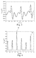
- Figures 3 and 4 are graphical simulations of the curves of effective power voltage values in response to flicker noise induced in the mains, when the power circuit of Figure 1 is implemented ( Figure 3 ) or not implemented ( Figure 4 ) in an electric welding machine respectively, particularly when there is a power failure.
Landscapes
- Engineering & Computer Science (AREA)
- Mechanical Engineering (AREA)
- Physics & Mathematics (AREA)
- Plasma & Fusion (AREA)
- Generation Of Surge Voltage And Current (AREA)
- Dc-Dc Converters (AREA)
- Arc Welding Control (AREA)
Priority Applications (2)
| Application Number | Priority Date | Filing Date | Title |
|---|---|---|---|
| EP09425412A EP2314409A1 (fr) | 2009-10-20 | 2009-10-20 | Machine à souder électrique dotée d'un circuit électrique pour limiter les fluctuations de tensions induites dans le réseau électrique |
| EP10177723.3A EP2329904B1 (fr) | 2009-10-20 | 2010-09-20 | Machine à souder électrique dotée d'un circuit électrique pour limiter les fluctions de tecnsions induites dans le réseau électrique |
Applications Claiming Priority (1)
| Application Number | Priority Date | Filing Date | Title |
|---|---|---|---|
| EP09425412A EP2314409A1 (fr) | 2009-10-20 | 2009-10-20 | Machine à souder électrique dotée d'un circuit électrique pour limiter les fluctuations de tensions induites dans le réseau électrique |
Publications (1)
| Publication Number | Publication Date |
|---|---|
| EP2314409A1 true EP2314409A1 (fr) | 2011-04-27 |
Family
ID=42060485
Family Applications (2)
| Application Number | Title | Priority Date | Filing Date |
|---|---|---|---|
| EP09425412A Withdrawn EP2314409A1 (fr) | 2009-10-20 | 2009-10-20 | Machine à souder électrique dotée d'un circuit électrique pour limiter les fluctuations de tensions induites dans le réseau électrique |
| EP10177723.3A Not-in-force EP2329904B1 (fr) | 2009-10-20 | 2010-09-20 | Machine à souder électrique dotée d'un circuit électrique pour limiter les fluctions de tecnsions induites dans le réseau électrique |
Family Applications After (1)
| Application Number | Title | Priority Date | Filing Date |
|---|---|---|---|
| EP10177723.3A Not-in-force EP2329904B1 (fr) | 2009-10-20 | 2010-09-20 | Machine à souder électrique dotée d'un circuit électrique pour limiter les fluctions de tecnsions induites dans le réseau électrique |
Country Status (1)
| Country | Link |
|---|---|
| EP (2) | EP2314409A1 (fr) |
Cited By (2)
| Publication number | Priority date | Publication date | Assignee | Title |
|---|---|---|---|---|
| CN102248255A (zh) * | 2011-06-15 | 2011-11-23 | 太原市星云焊接设备有限公司 | 全数字化多功能无飞溅逆变焊机 |
| CN118595564A (zh) * | 2024-06-28 | 2024-09-06 | 深圳市汇芯通信技术有限公司 | 电焊机的电流控制电路和电焊机 |
Families Citing this family (1)
| Publication number | Priority date | Publication date | Assignee | Title |
|---|---|---|---|---|
| CN103111744B (zh) * | 2013-01-15 | 2015-05-13 | 苏州华亚电讯设备有限公司 | 一种电容储能无变压器多功能电焊机 |
Citations (4)
| Publication number | Priority date | Publication date | Assignee | Title |
|---|---|---|---|---|
| US5786992A (en) * | 1994-04-08 | 1998-07-28 | Vlt Corporation | Efficient power conversion |
| US5991169A (en) * | 1998-03-16 | 1999-11-23 | Lincoln Global, Inc. | Arc welding power supply |
| WO2003015973A1 (fr) * | 2001-08-20 | 2003-02-27 | Lincoln Global, Inc. | Appareil de soudure a l'arc electrique a tension d'entree alternative variable |
| US7564706B1 (en) * | 2006-06-23 | 2009-07-21 | Edward Herbert | Power factor corrected single-phase AC-DC power converter using natural modulation |
Family Cites Families (1)
| Publication number | Priority date | Publication date | Assignee | Title |
|---|---|---|---|---|
| ITPD20010182A1 (it) * | 2001-07-19 | 2003-01-19 | Selco Srl | Generatore per apparecchi di saldatura ad arco a fattore di potenza unitario. |
-
2009
- 2009-10-20 EP EP09425412A patent/EP2314409A1/fr not_active Withdrawn
-
2010
- 2010-09-20 EP EP10177723.3A patent/EP2329904B1/fr not_active Not-in-force
Patent Citations (4)
| Publication number | Priority date | Publication date | Assignee | Title |
|---|---|---|---|---|
| US5786992A (en) * | 1994-04-08 | 1998-07-28 | Vlt Corporation | Efficient power conversion |
| US5991169A (en) * | 1998-03-16 | 1999-11-23 | Lincoln Global, Inc. | Arc welding power supply |
| WO2003015973A1 (fr) * | 2001-08-20 | 2003-02-27 | Lincoln Global, Inc. | Appareil de soudure a l'arc electrique a tension d'entree alternative variable |
| US7564706B1 (en) * | 2006-06-23 | 2009-07-21 | Edward Herbert | Power factor corrected single-phase AC-DC power converter using natural modulation |
Cited By (3)
| Publication number | Priority date | Publication date | Assignee | Title |
|---|---|---|---|---|
| CN102248255A (zh) * | 2011-06-15 | 2011-11-23 | 太原市星云焊接设备有限公司 | 全数字化多功能无飞溅逆变焊机 |
| CN102248255B (zh) * | 2011-06-15 | 2013-09-18 | 太原市星云焊接设备有限公司 | 全数字化多功能无飞溅逆变焊机 |
| CN118595564A (zh) * | 2024-06-28 | 2024-09-06 | 深圳市汇芯通信技术有限公司 | 电焊机的电流控制电路和电焊机 |
Also Published As
| Publication number | Publication date |
|---|---|
| EP2329904A2 (fr) | 2011-06-08 |
| EP2329904B1 (fr) | 2015-07-08 |
| EP2329904A3 (fr) | 2012-06-13 |
Similar Documents
| Publication | Publication Date | Title |
|---|---|---|
| JP4253341B2 (ja) | 放電ランプ点灯制御装置 | |
| JP6603927B1 (ja) | プラズマ装置用直流パルス電源装置 | |
| KR102920273B1 (ko) | 무정전 전원 장치 | |
| JP5310560B2 (ja) | 高圧放電ランプ点灯装置 | |
| EP2314409A1 (fr) | Machine à souder électrique dotée d'un circuit électrique pour limiter les fluctuations de tensions induites dans le réseau électrique | |
| JP5008600B2 (ja) | スイッチング電源装置 | |
| JP5513249B2 (ja) | コンデンサ式抵抗溶接機 | |
| JP2007109609A (ja) | 燃料電池システムの充放電装置 | |
| CN100592613C (zh) | Dc-dc变换器及使用其的高压放电灯点灯装置 | |
| EP1739819A1 (fr) | Appareil d'alimentation électrique | |
| US5696670A (en) | Power supply for arc-discharge load | |
| US20040046460A1 (en) | Apparatus for the voltage maintenance of an electrical AC voltage supply network and method for operating such an apparatus | |
| JP4030550B2 (ja) | 電源装置 | |
| JP2012125085A (ja) | 瞬時電圧低下保護装置 | |
| JP2012175809A (ja) | スイッチング電源装置 | |
| JP4179173B2 (ja) | 放電灯点灯装置、照明装置、プロジェクタ | |
| JP3981208B2 (ja) | アーク加工用電源装置 | |
| JP4984062B2 (ja) | 放電灯点灯装置 | |
| US8351225B2 (en) | System-interconnected inverter | |
| JP4932604B2 (ja) | 電圧補償装置 | |
| JP6692168B2 (ja) | Ups機能を有する蓄電装置及びups機能を有する蓄電装置の制御方法 | |
| JP2006238510A (ja) | 電源装置 | |
| JP2799975B2 (ja) | パルス型電磁石用電源装置 | |
| JP4970898B2 (ja) | 放電灯点灯装置 | |
| JP2006073441A (ja) | 高圧放電灯点灯装置及び照明装置 |
Legal Events
| Date | Code | Title | Description |
|---|---|---|---|
| PUAI | Public reference made under article 153(3) epc to a published international application that has entered the european phase |
Free format text: ORIGINAL CODE: 0009012 |
|
| AK | Designated contracting states |
Kind code of ref document: A1 Designated state(s): AT BE BG CH CY CZ DE DK EE ES FI FR GB GR HR HU IE IS IT LI LT LU LV MC MK MT NL NO PL PT RO SE SI SK SM TR |
|
| AX | Request for extension of the european patent |
Extension state: AL BA RS |
|
| STAA | Information on the status of an ep patent application or granted ep patent |
Free format text: STATUS: THE APPLICATION IS DEEMED TO BE WITHDRAWN |
|
| 18D | Application deemed to be withdrawn |
Effective date: 20111028 |