EP2314433B1 - Negativform zur Herstellung eines ein Gerinne aufweisenden Schachtunterteils sowie Verfahren zur Herstellung eines derartigen Schachtunterteils - Google Patents
Negativform zur Herstellung eines ein Gerinne aufweisenden Schachtunterteils sowie Verfahren zur Herstellung eines derartigen Schachtunterteils Download PDFInfo
- Publication number
- EP2314433B1 EP2314433B1 EP20100009679 EP10009679A EP2314433B1 EP 2314433 B1 EP2314433 B1 EP 2314433B1 EP 20100009679 EP20100009679 EP 20100009679 EP 10009679 A EP10009679 A EP 10009679A EP 2314433 B1 EP2314433 B1 EP 2314433B1
- Authority
- EP
- European Patent Office
- Prior art keywords
- core
- negative mould
- negative
- minutes
- melting
- Prior art date
- Legal status (The legal status is an assumption and is not a legal conclusion. Google has not performed a legal analysis and makes no representation as to the accuracy of the status listed.)
- Not-in-force
Links
- 238000004519 manufacturing process Methods 0.000 title claims description 8
- 239000011162 core material Substances 0.000 claims description 115
- 239000004567 concrete Substances 0.000 claims description 47
- 238000002844 melting Methods 0.000 claims description 35
- 230000008018 melting Effects 0.000 claims description 35
- 239000000463 material Substances 0.000 claims description 23
- 238000006243 chemical reaction Methods 0.000 claims description 16
- 238000000034 method Methods 0.000 claims description 9
- 239000012188 paraffin wax Substances 0.000 claims description 8
- 238000010309 melting process Methods 0.000 claims description 7
- 239000002184 metal Substances 0.000 claims description 7
- 239000004568 cement Substances 0.000 claims description 4
- 239000002986 polymer concrete Substances 0.000 claims description 4
- 239000000945 filler Substances 0.000 claims 1
- 238000000465 moulding Methods 0.000 description 6
- 239000000289 melt material Substances 0.000 description 4
- 238000003801 milling Methods 0.000 description 3
- 238000007711 solidification Methods 0.000 description 3
- 230000008023 solidification Effects 0.000 description 3
- 230000015572 biosynthetic process Effects 0.000 description 2
- 238000004049 embossing Methods 0.000 description 2
- 238000005755 formation reaction Methods 0.000 description 2
- 239000000155 melt Substances 0.000 description 2
- 229910000831 Steel Inorganic materials 0.000 description 1
- 206010000496 acne Diseases 0.000 description 1
- 230000002411 adverse Effects 0.000 description 1
- 150000001875 compounds Chemical class 0.000 description 1
- 238000004590 computer program Methods 0.000 description 1
- 230000001419 dependent effect Effects 0.000 description 1
- 210000003608 fece Anatomy 0.000 description 1
- 238000009434 installation Methods 0.000 description 1
- 239000010871 livestock manure Substances 0.000 description 1
- 238000012423 maintenance Methods 0.000 description 1
- 230000000717 retained effect Effects 0.000 description 1
- 238000000926 separation method Methods 0.000 description 1
- 239000010959 steel Substances 0.000 description 1
Images


Classifications
-
- B—PERFORMING OPERATIONS; TRANSPORTING
- B28—WORKING CEMENT, CLAY, OR STONE
- B28B—SHAPING CLAY OR OTHER CERAMIC COMPOSITIONS; SHAPING SLAG; SHAPING MIXTURES CONTAINING CEMENTITIOUS MATERIAL, e.g. PLASTER
- B28B7/00—Moulds; Cores; Mandrels
- B28B7/34—Moulds, cores, or mandrels of special material, e.g. destructible materials
- B28B7/342—Moulds, cores, or mandrels of special material, e.g. destructible materials which are at least partially destroyed, e.g. broken, molten, before demoulding; Moulding surfaces or spaces shaped by, or in, the ground, or sand or soil, whether bound or not; Cores consisting at least mainly of sand or soil, whether bound or not
-
- B—PERFORMING OPERATIONS; TRANSPORTING
- B28—WORKING CEMENT, CLAY, OR STONE
- B28B—SHAPING CLAY OR OTHER CERAMIC COMPOSITIONS; SHAPING SLAG; SHAPING MIXTURES CONTAINING CEMENTITIOUS MATERIAL, e.g. PLASTER
- B28B7/00—Moulds; Cores; Mandrels
- B28B7/16—Moulds for making shaped articles with cavities or holes open to the surface, e.g. with blind holes
- B28B7/168—Moulds for making shaped articles with cavities or holes open to the surface, e.g. with blind holes for holders or similar hollow articles, e.g. vaults, sewer pits
-
- B—PERFORMING OPERATIONS; TRANSPORTING
- B28—WORKING CEMENT, CLAY, OR STONE
- B28B—SHAPING CLAY OR OTHER CERAMIC COMPOSITIONS; SHAPING SLAG; SHAPING MIXTURES CONTAINING CEMENTITIOUS MATERIAL, e.g. PLASTER
- B28B7/00—Moulds; Cores; Mandrels
- B28B7/34—Moulds, cores, or mandrels of special material, e.g. destructible materials
- B28B7/346—Manufacture of moulds
Definitions
- the invention relates to a negative mold for producing a gutter having manhole base, with a jacket, a form-fitting abutting the jacket bottom piece and a core which is surrounded by the jacket.
- the negative mold has a filling space for filling with a concrete mass or the like filling compound.
- the filling space is limited by the jacket, the core and the bottom piece.
- the filling space also projects beyond the core completely on the side of the negative mold opposite the bottom piece. This means that the jacket is formed higher on the side opposite the bottom piece of the negative mold than the core and thus also above the core, a filling space is present.
- the core also has a filling surface facing the boundary surface.
- a generic negative form is from the DE 10 2007 017 471 A1 known.
- the core consists of an inside hollow metal cylinder, on which a steel plate is placed, which in turn carries main body made of paraffin.
- a disadvantage of this negative form is that the metal cylinder of the core must be made shrinkable, so that the core after curing of the manhole base in the negative mold from the finished manhole base is separable. This creates a kind of seam in the area of the shrinkage point, at which the later shaft lower part is uneven.
- the metal cylinder are relatively expensive, and for manhole bases with different êtendruchmessern different metal cylinders must be stored in each case.
- the invention is therefore based on the object to provide a negative mold and a method of the type mentioned, in which the aforementioned disadvantages are avoided.
- the invention solves this problem by a negative mold with the features of claim 1 and by a method having the features of claim 10. Further advantageous embodiments of the invention are described in the dependent claims 2 to 9 and 11 to 15.
- At least the entire boundary surface of the core and the region to 10 mm below this boundary surface of a melting material whose melting point is between 20 ° C and 100 ° C and after a melting process and subsequent solidification has the same density as before the melting process.
- the melting material is completely or partially melted in the abovementioned region.
- the rigid portion of the core is thereby reduced relative to the original core before the melting process and can be easily removed from the finished manhole base.
- a shrinkage point of the core is no longer necessary, which is why no bumps in the finished manhole base in the region of this shrinkage point arise. Also, no shrinkable metal cores need to be stocked.
- the entire boundary surface is formed closed.
- the inner surface of the manhole base produced in the negative mold is very even and uniform.
- At least the entire boundary surface of the core and the region is integrally formed up to 10 mm below this boundary surface and consists of only one melting material.
- the entire core is formed in one piece and consisting of only one melting material. This embodiment simplifies the handling and manufacture of the core.
- the melting material is a hardparfin having a melting point between 40 ° C and 90 ° C, preferably between 45 ° C and 80 ° C, more preferably between 50 ° C and 70 ° C and in particular between 55 ° C and 65 ° C.
- the concrete mass solidifies in the marginal areas of the mantle, the bottom piece and the core increasingly, without already sufficient heat of reaction has formed to melt parts of the core. It is only during the subsequent hardening of the concrete mass in the negative mold that so much heat of reaction is produced that the hard paraffin melts without introduction of further heat solely by the heat of reaction and the remaining, still hard parts of the core can be removed from the negative mold and / or fall out.
- the molten hard paraffin of the core also flows out of the negative mold.
- the melt material of the core is then melted down and reused to make a new core. It has been found that especially hard paraffin with the abovementioned melting point range is suitable for being melted sufficiently in the near-surface regions of the core solely by the resulting heat of reaction.
- the bottom piece has a bottom piece by cross-recess, which is positively filled in cross-section of the core.
- a circular recess has the bottom piece for example, the shape of a ring.
- the bottom piece lies as a kind of bottom sleeve form fit on the jacket. On the one hand, this achieves that the position of the core is fixed relative to the bottom piece and the jacket. At the same time it is achieved that no concrete mass penetrate between the core and bottom piece and thereby adversely affect the desired shape of the manhole base to be produced.
- the bottom piece preferably has a contour on its inner side facing the filling space, which forms a negative molding for the contour of the manhole base to be produced in the negative mold.
- At least one functional element made of a material having a melting point above 100 ° C., for example made of metal or rubber, is fixed in a defined position within the filling space by means of holding elements.
- the holding elements also consist of the aforementioned melting material, which is also part of the core.
- the core has recesses in the melting material, the negative forms for nubs in the region of a berm of the negative mold to be produced Forming manhole bases.
- the berm has a slope in the manhole base to the located in the middle of the manhole base flume.
- moisture is the Berme slippery.
- the recesses may also form a negative molding for embossing with an individual identification of the manhole base to be produced with the negative mold.
- a concrete mass for example a cement-bound concrete or a polymer concrete
- a negative mold with one of the abovementioned refinements. After solidification of the concrete mass at the inner side facing the core of the core is partially melted and removed from the negative mold.
- the core is previously milled automatically from a raw core.
- the milling work is preferably carried out by means of a robot arm, which mills out a defined contour from the raw core via a computer program.
- the concrete mass is preferably formed of cement-bound concrete, which after filling into the filling space within a period of 3 hours to 12 hours, preferably within a period of 3.5 hours to 10 hours, more preferably within a period of 4 hours to 8 hours and in particular developed within a period of 4.5 hours to 6 hours, a compressive strength of more than 20 N / mm2.
- the concrete mass can also be advantageously formed from a polymer concrete which after filling into the filling space within a period of 10 minutes to 120 minutes, preferably within a period of 15 minutes to 90 minutes, particularly preferably within a period of 20 minutes developed a compressive strength of more than 20 N / mm2 to 60 minutes and especially within a period of 25 minutes to 40 minutes.
- the melting of the core is due to an increase in temperature, which is based solely on a resulting during curing of the concrete mass reaction heat.
- the introduction of additional heat in the core is therefore no longer necessary.
- the core material is used again after removal from the negative mold for the production of a Rohkerns.
- the cores can be produced inexpensively.
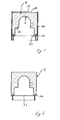
- Fig. 1 to Fig. 8 show different stages in the course of the process according to the invention for producing a manure 2 having manhole base 4 by means of a negative mold. 6
- Fig. 1 shows a raw core 8 made of hard paraffin.
- a core 10 is milled by means not shown in the drawings robot arm, the in Fig. 2 is shown.
- the dashed line shows the original contour of the raw core 8.
- the milling process and the resulting contour of the core 10 is given to the robot arm by means of a controller, for example by means of a computer running a CAD program.
- the core 10 is then assembled to form the inner contour of the manhole base 4 with the other components of the negative mold 6.
- the negative mold 6 has an outer shell 12, a bottom surface 14 which bears against the casing 12 in a form-fitting manner, the core 10 and a filling space 16 for filling with a concrete mass 18 or the like Fig. 3 is apparent.
- the filling room is bounded from the outside by the jacket 12, from below through the bottom piece 14 and from the inside through the core 10.
- On the opposite side of the bottom piece 14 of the filling chamber 16 projects beyond the core 10 completely. From this side, the filling space 16 is filled with concrete mass 18.
- the manhole base 4 to be produced in the negative mold 6 thus stands upside down during production relative to the later application position of the manhole base 4.
- the core 10 has a filling surface 16 facing the boundary surface 20.
- the entire boundary surface 20 of the core 10 and the area up to 10 mm below this boundary surface 20 consists of a melting material, the melting point between 20 ° C and 100 ° C and after melting and subsequent solidification has the same density as before the melting process ,
- the entire boundary surface 20 is formed closed.
- the entire core 10 is integrally formed and consists only of a melting material.
- the bottom piece 14 has a bottom piece 14 by cross-recess 22 which is positively filled in cross-section of the core 10.
- the core 10 is thus annularly surrounded by the bottom piece 14, wherein the material of the core 10 and the bottom piece 14 lie against each other in a form-fitting manner.
- the position of the core 10 relative to the bottom piece 14 and the shell 12 is thereby fixed.
- no concrete mass 18 between core 10 and bottom piece 14 penetrate.
- the bottom piece 14 has at its inner side located to the filling space 16 on a contour 24, which forms a negative molding for the contour of the produced in the negative mold 6 manhole base 4.
- the filling space 16 is filled after assembly of the negative mold 6 with the concrete mass 18, as in Fig. 4 shown.
- the concrete mass 18 begins to set, so that the concrete mass begins to harden.
- the resulting reaction temperature within the concrete mass 18 is initially so small that the melting point of the core material is not exceeded in the edge region of the concrete mass 18 toward the core 10. It is only with increasing time and constant increase of the heat of reaction resulting from the setting that the reaction process of further setting increases in intensity. This is accompanied by a significant increase in the resulting heat of reaction within the concrete mass 18.
- the concrete mass 18 reaches a temperature which is above the melting point of the core material and thereby melts the material of the core 10 in the areas near the boundary surface 20 of the core 10.
- the core material as well as the remaining parts of the core 10 flow and / or fall out of the negative mold 6 through the recess 22 of the bottom piece 14 until the entire core material is removed from the interior of the manhole base 4 to be produced, as in FIG Fig. 5 shown.
- the concrete mass 18 so far hardens that the predetermined by the core 10 contour of the inner region of the manhole base 4 to be produced even when removing the core 10th preserved.
- the core 10 therefore has no technical function at this time.
- Fig. 7 shows the finished manhole base 4 in the positioning in which it was made.
- Fig. 8 shows, however, the use position of the finished manhole base 4, ie its installation position in a channel system.
- FIGS. 9 and 10 show a further negative mold according to the invention 6.
- holding elements 26 are embedded in the core 10, which also consist of hard paraffin and protrude into the functional space 16.
- the holding elements 26 fix functional elements 28 in a desired position within the filling space 16.
- Fig. 10 shows their positioning relative to the channel 2 to be produced in a side view.
- the in Fig. 10 The illustrated core 10 has recesses 30 which form negative protrusions for dimples in the region of a berm 32 of the manhole base 4 to be produced with the negative mold 6.
- the core 10 has further recesses 34 and / or formations which form further negative moldings for embossing with an individual marking of the manhole base 4 to be produced with the negative mold 6.
Landscapes
- Engineering & Computer Science (AREA)
- Manufacturing & Machinery (AREA)
- Chemical & Material Sciences (AREA)
- Ceramic Engineering (AREA)
- Mechanical Engineering (AREA)
- Moulds, Cores, Or Mandrels (AREA)
- Underground Structures, Protecting, Testing And Restoring Foundations (AREA)
Description
- Die Erfindung betrifft eine Negativform zur Herstellung eines ein Gerinne aufweisenden Schachtunterteils, mit einem Mantel, einem formschlüssig am Mantel anliegenden Bodenstück und mit einem Kern, der von dem Mantel umgeben ist. Die Negativform weist einen Füllraum zum Befüllen mit einer Betonmasse oder dergleichen Füllmasse auf. Der Füllraum ist von dem Mantel, dem Kern und dem Bodenstück begrenzt. Der Füllraum überragt zudem auf der dem Bodenstück gegenüberliegenden Seite der Negativform den Kern vollständig. Das bedeutet, dass der Mantel auf der dem Bodenstück gegenüberliegenden Seite der Negativform höher ausgebildet ist als der Kern und dadurch oberhalb des Kerns ebenfalls ein Füllraum vorhanden ist. Der Kern weist zudem eine dem Füllraum zugewandte Begrenzungsoberfläche auf.
- Eine gattungsgemäße Negativform ist aus der
DE 10 2007 017 471 A1 bekannt. Der Kern besteht dort aus einem innen hohlen Metallzylinder, auf den eine Stahlplatte aufgesetzt ist, die wiederum Grundkörper aus Parafin trägt. Nachteilig an dieser Negativform ist jedoch, dass der Metallzylinder des Kerns schrumpfbar ausgebildet sein muss, damit der Kern nach dem Aushärten des Schachtunterteils in der Negativform vom fertigen Schachtunterteil trennbar ist. Dabei entsteht im Bereich der Schrumpfstelle eine Art Naht, an der das spätere Schachtunterteil uneben ist. Zudem sind die Metallzylinder verhältnismäßig teuer, und für Schachtunterteile mit unterschiedlichem Innendruchmessern müssen jeweils unterschiedliche Metallzylinder bevorratet werden. - Der Erfindung liegt daher die Aufgabe zugrunde, eine Negativform sowie ein Verfahren der Eingangs genannten Art bereitzustellen, bei denen die vorgenannten Nachteile vermieden werden.
- Die Erfindung löst diese Aufgabe durch eine Negativform mit den Merkmalen des Anspruchs 1 sowie durch ein Verfahren mit den Merkmalen des Anspruchs 10. Weitere vorteilhafte Ausgestaltungen der Erfindung sind den Unteransprüchen 2 bis 9 sowie 11 bis 15 zu entnehmen.
- Erfindungsgemäß besteht zumindest die gesamte Begrenzungsoberfläche des Kerns sowie der Bereich bis 10 mm unterhalb dieser Begrenzungsoberfläche aus einem Schmelzmaterial, dessen Schmelzpunkt zwischen 20 °C und 100 °C liegt und das nach einem Schmelzvorgang und anschließendem Erstarren die gleiche Dichte aufweist, wie vor dem Schmelzvorgang. Zur Entnahme des Kerns aus dem erstarrten Schachtunterteil wird das Schmelzmaterial in dem vorgenannten Bereich ganz oder teilweise geschmolzen. Der starre Anteil des Kerns verkleinert sich dadurch relativ zum ursprünglichen Kern vor dem Schmelzvorgang und kann leicht aus dem fertigen Schachtunterteil entnommen werden. Eine Schrumpfstelle des Kerns ist hierzu nicht mehr erforderlich, weshalb auch keine Unebenheiten im fertigen Schachtunterteil im Bereich dieser Schrumpfstelle entstehen. Auch müssen keine schrumpfbaren Metallkerne bevorratet werden.
- Mit Vorteil ist die gesamte Begrenzungsoberfläche geschlossen ausgebildet. Hierdurch ist die innere Oberfläche des in der Negativform hergestellten Schachtunterteils sehr eben und gleichmäßig.
- In einer bevorzugten Ausgestaltung der Erfindung ist zumindest die gesamte Begrenzungsoberfläche des Kerns sowie der Bereich bis 10 mm unterhalb dieser Begrenzungsoberfläche einstückig ausgebildet und besteht aus dem nur einen Schmelzmaterial. Durch diese Ausgestaltung wird erreicht, dass Ausformungen und Ausnehmungen des Kerns als Negativausformung zur Herstellung des Gerinnes so wie weiterer Funktionselemente des späteren Schachtunterteils sehr einfach mittels Roboterarm in den Kern eingefräst werden können. Die Begrenzungsoberfläche des Kerns und auch der Bereich bis 10 mm unterhalb dieser Begrenzungsoberfläche ist auch nach einem derartigen Fräsvorgang noch einstückig und ausschließlich aus dem einen Schmelzmaterial bestehend aufgebaut. Zudem wird dadurch erreicht, dass das Schmelzmaterial nach der Verwendung in dem Kern eingeschmolzen und erneut für die Herstellung eines neuen Kerns verwendet werden kann. Eine Trennung verschiedener Schmelzmaterialien ist hierzu nicht erforderlich.
- In einer besonders bevorzugten Ausgestaltung der Erfindung ist der gesamte Kern einstückig und nur aus dem einen Schmelzmaterial bestehend ausgebildet. Diese Ausgestaltung vereinfacht die Handhabung und Herstellung des Kerns.
- Mit Vorteil ist das Schmelzmaterial ein Hartparfin mit einem Schmelzpunkt zwischen 40 °C und 90 °C, bevorzugt zwischen 45°C und 80 °C, besonders bevorzugt zwischen 50 °C und 70 °C und insbesondere zwischen 55 °C und 65 °C. Nach dem Eingießen der Betonmasse in den Füllraum der Negativform verfestigt sich die Betonmasse in den Randbereichen zum Mantel, zum Bodenstück und zum Kern zunehmend, ohne dass bereits ausreichend Reaktionswärme entstanden ist, um Teile des Kerns zu schmelzen. Erst beim anschließenden Aushärten der Betonmasse in der Negativform entsteht gerade so viel Reaktionswärme, dass das Hartparafin ohne Einbringen weiterer Wärme allein durch die Reaktionswärme schmilzt und die verbleibenden, noch harten Teile des Kerns aus der Negativform entnommen werden können und/oder herausfallen. Das geschmolzene Hartparafin des Kerns fließt ebenfalls aus der Negativform heraus. Das Schmelzmaterial des Kerns wird anschließend eingeschmolzen und zur Herstellung eines neuen Kerns erneut verwendet. Es hat sich gezeigt, dass gerade Hartparafin mit dem vorgenannten Schmelzpunktbereich geeignet ist, allein durch die entstehende Reaktionswärme ausreichend in den oberflächennahen Regionen des Kerns geschmolzen zu werden.
- In einer vorteilhaften Ausgestaltung der Erfindung weist das Bodenstück eine das Bodenstück durchgreifende Ausnehmung auf, die im Querschnitt formschlüssig vom Kern ausgefüllt ist. Im Falle einer kreisförmigen Ausnehmung hat das Bodenstück beispielsweise die Form eines Ringes. Das Bodenstück liegt dabei als eine Art Untermuffe formschlüssig am Mantel an. Einerseits wird dadurch erreicht, dass die Position des Kerns relativ zum Bodenstück und zum Mantel fixiert wird. Gleichzeitig wird erreicht, dass keine Betonmasse zwischen Kern und Bodenstück eindringen und dadurch die erwünschte Form des herzustellenden Schachtunterteils nachteilig beeinflussen kann.
- Das Bodenstück weist zudem bevorzugt an dessen zum Füllraum gelegener Innenseite eine Kontur auf, die eine Negativausformung für die Kontur des in der Negativform herzustellenden Schachtunterteils bildet.
- In einer besonders bevorzugten Ausgestaltung der Erfindung ist zumindest ein Funktionselement aus einem Material mit einem Schmelzpunkt oberhalb von 100 °C, beispielsweise aus Metall oder Gummi, mittels Halteelementen in einer definierten Position innerhalb des Füllraums fixiert. Die Halteelemente bestehen dabei ebenfalls aus dem zuvor genannten Schmelzmaterial, das auch Bestandteil des Kerns ist. Durch diese Ausgestaltung wird das Funktionselement beim Einfüllen der Betonmasse in die Negativform in einer gewünschten Position gehalten, in der das Funktionselement in das Schachtunterteil integriert werden soll. Die Halteelemente müssen anschließend nicht aufwendig aus dem Schachtunterteil entfernt werden, sondern können einfach heraus geschmolzen werden.
- Mit Vorteil weist der Kern Ausnehmungen im Schmelzmaterial auf, die Negativausformungen für Noppen im Bereich einer Berme des mit der Negativform herzustellenden Schachtunterteils bilden. Die Berme weist in dem Schachtunterteil ein Gefälle zum in der Mitte des Schachtunterteils befindlichen Gerinne auf. Durch in dem Schachtunterteil im Betrieb befindliche Feuchtigkeit ist die Berme rutschig. Mit Hilfe der Noppen kann wirksam ein Ausrutschen von Personen verhindert werden, die auf der Berme stehen. Ergänzend oder alternativ hierzu können die Ausnehmungen auch eine Negativausformung für eine Prägung mit einer individuellen Kennzeichnung des mit der Negativform herzustellenden Schachtunterteils bilden. Mit Hilfe der individualisierten Kennzeichnung ist es möglich, Personen bei der Herstellung und/oder bei der Wartung eines Schachtes enthaltend eine Vielzahl der erfindungsgemäßen Schachtunterteile eine Hilfestellung, beispielsweise eine Positionsangabe, zu geben, die nicht im Laufe der Zeit verloren gehen kann, wie beispielsweise ein aufgeklebtes Etikett.
- Im Rahmen des erfindungsgemäßen Verfahrens zur Herstellung des ein Gerinne aufweisenden Schachtunterteils wird eine Betonmasse, beispielsweise ein zementgebundener Beton oder ein Polymerbeton, in eine Negativform mit einer der vorgenannten Ausgestaltungen gegossen. Nach dem Erstarren der Betonmasse an deren dem Kern zugewandten Innenseite wird der Kern teilweise geschmolzen und aus der Negativform entfernt.
- Der Kern wird zuvor automatisiert aus einem Rohkern gefräst. Die Fräsarbeit wird dabei bevorzugt mittels Roboterarm ausgeführt, der über ein Computerprogramm eine definierte Kontur aus dem Rohkern herausfräst. Durch diese Ausgestaltung ist es möglich, sehr individuelle Kerne herzustellen und dennoch nur wenige Rohkerne bevorraten zu müssen.
- Die Betonmasse wird bevorzugt von zementgebundenen Beton gebildet, der nach dem Einfüllen in den Füllraum innerhalb eines Zeitraumes von 3 Stunden bis 12 Stunden, bevorzugt innerhalb eines Zeitraumes von 3,5 Stunden bis 10 Stunden, besonders bevorzugt innerhalb eines Zeitraumes von 4 Stunden bis 8 Stunden und insbesondere innerhalb eines Zeitraumes von 4,5 Stunden bis 6 Stunden eine Druckfestigkeit von mehr als 20 N/mm2 entwickelt. Alternativ hierzu kann die Betonmasse auch mit Vorteil von einem Polymerbeton gebildet werden, der nach dem Einfüllen in den Füllraum innerhalb eines Zeitraumes von 10 Minuten bis 120 Minuten, bevorzugt innerhalb eines Zeitraumes von 15 Minuten bis 90 Minuten, besonders bevorzugt innerhalb eines Zeitraumes von 20 Minuten bis 60 Minuten und insbesondere innerhalb eines Zeitraumes von 25 Minuten bis 40 Minuten eine Druckfestigkeit von mehr als 20 N/mm2 entwickelt. Überraschenderweise hat sich gezeigt, dass speziell derartige zementgebundene Betone und/oder Polymerbetone während des Abbindens eine Reaktionswärme in einem Zeitintervall erzeugen, die ausreicht, um die oberflächennahen Bereich des Kerns schmelzen zu lassen, so dass der Kern entnommen werden kann und gleichzeitig die Temperatur der Betonmasse im Randbereich zum Kern erst dann den Schmelzpunkt des Schmelzmaterials übersteigt, wenn die Betonmasse bereits eine ausreichende Druckfestigkeit aufweist, damit die Kontur des Innenraumes des herzustellenden Schachtunterteils auch nach Entfernen des Kerns erhalten bleibt. Die Betonmasse beginnt nach dem Einfüllen in den Füllraum abzubinden, so dass die Betonmasse anfängt zu erhärten. Die dabei entstehende Reaktionstemperatur innerhalb der Betonmasse ist aufgrund der speziellen vorgenannten Eigenschaft der Betonmasse anfangs noch so gering, dass im Randbereich der Betonmasse zum Kern hin die Schmelztemperatur des Schmelzmaterials nicht überschritten wird. Erst mit zunehmender Zeit und ständiger Steigerung der durch das Abbinden entstehenden Reaktionswärme nimmt auch der Reaktionsprozess des weiteren Abbindens an Intensität zu. Damit geht ein deutlicher Anstieg der entstehenden Reaktionswärme innerhalb der Betonmasse einher. Im Randbereich zum Kern erreicht die Betonmasse aufgrund der speziellen vorgenannten Eigenschaft der Betonmasse schließlich eine Temperatur, die oberhalb des Schmelzpunktes des Kernmaterials liegt und dadurch das Material des Kerns in den Bereichen nahe der Begrenzungsoberfläche des Kerns zum Schmelzen bringt. Bereits zu Beginn des Schmelzens des Kerns ist die Betonmasse jedoch schon so weit erhärtet, dass die durch den Kern vorgegebene Kontur des Innenbereichs des herzustellenden Schachtunterteils auch bei Entfernen des Kerns erhalten bleibt.
- Mit Vorteil erfolgt der Schmelzvorgang des Kerns aufgrund einer Temperaturerhöhung, die ausschließlich auf einer beim Aushärten der Betonmasse entstehenden Reaktionswärme beruht. Das Einbringen einer zusätzlichen Wärme in den Kern ist dadurch nicht mehr erforderlich.
- Mit Vorteil wird das Kernmaterial nach dem Entfernen aus der Negativform erneut zur Herstellung eines Rohkerns verwendet. Dadurch muss lediglich eine geringe Menge Kernmaterial bereitgestellt und die Kerne können kostengünstig hergestellt werden.
- Weitere vorteilhafte Ausgestaltungen und Details der Erfindung sind dem nachfolgend beschriebenen schematischen Ausführungsbeispiel der Erfindung zu entnehmen; es zeigen:
- Fig. 1
- einen Rohkern aus Parafin,
- Fig. 2
- einen erfindungsgemäßen Kern herausgefräst aus dem Rohkern nach
Fig. 1 , - Fig. 3
- den Kern aus
Fig. 2 eingesetzt in eine erfindungsgemäße Negativform, - Fig. 4
- die Negativform aus
Fig. 3 gefüllt mit Betonmasse, - Fig. 5
- den Gegenstand aus
Fig. 4 mit angehärtetem Beton und entferntem Kern - Fig. 6
- den Gegenstand aus
Fig. 5 mit entfernetem Mantel, - Fig. 7
- das fertige Schachtunterteil aus
Fig. 6 , - Fig. 8
- den Gegenstand aus
Fig. 7 in Gebrauchsposition, - Fig. 9
- eine weitere erfindungsgemäße Negativform in einer schematisierten Aufsicht und
- Fig. 10
- den Gegenstand aus
Fig. 9 in einer geschnittenen Ansicht von der Seite. - Nachfolgend werden gleichwirkende Elemente der Erfindung mit einheitlichen Bezugsziffern versehen, sofern dies sinnvoll ist.
-
Fig. 1 bis Fig. 8 zeigen unterschiedliche Stadien im Verlaufe des erfindungsgemäßen Verfahrens zur Herstellung eines ein Gerinne 2 aufweisenden Schachtunterteils 4 mit Hilfe einer Negativform 6. -
Fig. 1 zeigt einen Rohkern 8 aus Hartparafin. Aus diesem Rohkern 8 wird mittels in den Zeichnungen nicht dargestelltem Roboterarm ein Kern 10 herausgefräst, der inFig. 2 abgebildet ist. Die gestrichelte Linie zeigt die ursprüngliche Kontur des Rohkerns 8. Der Fräsvorgang und die sich daraus ergebende Kontur des Kerns 10 wird dem Roboterarm mittels einer Steuerung vorgegeben, beispielsweise mittels eines Rechners, auf dem ein CAD-Programm läuft. - Der Kern 10 wird anschließend zur Formgebung der inneren Kontur des Schachtunterteils 4 mit den weiteren Komponenten der Negativform 6 zusammengesetzt. Die Negativform 6 weist einen äußeren Mantel 12, ein formschlüssig am Mantel 12 anliegendes Bodenstück 14, den Kern 10 sowie einen Füllraum 16 zum Befüllen mit einer Betonmasse 18 o. dgl. Füllmasse auf, wie aus
Fig. 3 ersichtlich ist. Der Füllraum wird dabei von außen durch den Mantel 12, von unten durch das Bodenstück 14 und von innen durch den Kern 10 begrenzt. Auf der dem Bodenstück 14 gegenüberliegenden Seite überragt der Füllraum 16 den Kern 10 vollständig. Von dieser Seite wird der Füllraum 16 mit Betonmasse 18 befüllt. Das in der Negativform 6 herzustellende Schachtunterteil 4 steht somit während der Herstellung relativ zur späteren Anwendungsposition des Schachtunterteils 4 auf dem Kopf. - Der Kern 10 weist eine dem Füllraum 16 zugewandte Begrenzungsoberfläche 20 auf. Die gesamte Begrenzungsoberfläche 20 des Kerns 10 sowie der Bereich bis 10 mm unterhalb dieser Begrenzungsoberfläche 20 besteht aus einem Schmelzmaterial, dessen Schmelzpunkt zwischen 20°C und 100°C liegt und das nach einem Schmelzvorgang und anschließendem Erstarren die gleiche Dichte aufweist, wie vor dem Schmelzvorgang. Im Ausführungsbeispiel ist die gesamte Begrenzungsoberfläche 20 geschlossen ausgebildet. Zudem ist der gesamte Kern 10 einstückig ausgebildet und besteht nur aus dem einen Schmelzmaterial.
- Das Bodenstück 14 weist eine das Bodenstück 14 durchgreifende Ausnehmung 22 auf, die im Querschnitt formschlüssig vom Kern 10 ausgefüllt ist. Der Kern 10 ist somit ringartig von dem Bodenstück 14 umgeben, wobei das Material des Kerns 10 und das Bodenstück 14 formschlüssig aneinanderliegen. Die Position des Kerns 10 relativ zum Bodenstück 14 und zum Mantel 12 wird dadurch fixiert. Zudem kann keine Betonmasse 18 zwischen Kern 10 und Bodenstück 14 eindringen.
- Das Bodenstück 14 weist an dessen zum Füllraum 16 gelegener Innenseite eine Kontur 24 auf, die eine Negativausformung für die Kontur des in der Negativform 6 herzustellenden Schachtunterteils 4 bildet.
- Der Füllraum 16 wird nach Zusammensetzen der Negativform 6 mit der Betonmasse 18 befüllt, wie in
Fig. 4 dargestellt. Die Betonmasse 18 beginnt abzubinden, so dass die Betonmasse anfängt zu erhärten. Die dabei entstehende Reaktionstemperatur innerhalb der Betonmasse 18 ist anfangs noch so gering, dass im Randbereich der Betonmasse 18 zum Kern 10 hin die Schmelztemperatur des Kernmaterials nicht überschritten wird. Erst mit zunehmender Zeit und ständiger Steigerung der durch das Abbinden entstehenden Reaktionswärme nimmt auch der Reaktionsprozess des weiteren Abbindens an Intensität zu. Damit geht ein deutlicher Anstieg der entstehenden Reaktionswärme innerhalb der Betonmasse 18 einher. Im Randbereich zum Kern 10 erreicht die Betonmasse 18 schließlich eine Temperatur, die oberhalb des Schmelzpunktes des Kernmaterials liegt und dadurch das Material des Kerns 10 in den Bereichen nahe der Begrenzungsoberfläche 20 des Kerns 10 zum Schmelzen bringt. Das Kernmaterial sowie die übriggebliebenen Teile des Kerns 10 fließen und/oder fallen durch die Ausnehmung 22 des Bodenstücks 14 aus der Negativform 6 heraus, bis das gesamte Kernmaterial aus dem Innenbereich des herzustellenden Schachtunterteils 4 entfernt ist, wie inFig. 5 dargestellt. Bereits zu Beginn des Schmelzens des Kerns 10 aufgrund der zunehmenden Reaktionswärme und der damit einhergehenden Temperaturerhöhung der Betonmasse 18 ist die Betonmasse 18 so weit erhärtet, dass die durch den Kern 10 vorgegebene Kontur des Innenbereichs des herzustellenden Schachtunterteils 4 auch bei Entfernen des Kerns 10 erhalten bleibt. Der Kern 10 hat daher bereits zu diesem Zeitpunkt keine technische Funktion mehr. - Nach dem weiteren Erhärten der Betonmasse 18 wird zunächst der Mantel 12 und später das Bodenstück 14 entfernt, wie in den
Fig. 6 und7 dargestellt.Fig. 7 zeigt dabei das fertige Schachtunterteil 4 in der Positionierung, in der es hergestellt wurde.Fig. 8 zeigt hingegen die Gebrauchsposition des fertigen Schachtunterteils 4, d.h. dessen Einbauposition in einem Kanalsystem. -
Fig. 9 und Fig. 10 zeigen eine weitere erfindungsgemäße Negativform 6. Im Bereich einer Negativausformung für das herzustellende Gerinne 2 des späteren Schachtunterteils 4 sind Halteelemente 26 in den Kern 10 eingelassen, die ebenfalls aus Hartparafin bestehen und in den Funktionsraum 16 hineinragen. Die Halteelemente 26 fixieren Funktionselemente 28 in einer gewünschten Position innerhalb des Füllraums 16.Fig. 10 zeigt deren Positionierung relativ zum herzustellenden Gerinne 2 in einer Seitendarstellung. Der inFig. 10 abgebildete Kern 10 weist Ausnehmungen 30 auf, die Negativausformungen für Noppen im Bereich einer Berme 32 des mit der Negativform 6 herzustellenden Schachtunterteils 4 bilden. Zudem weist der Kern 10 weitere Ausnehmungen 34 und/oder Ausformungen auf, die weitere Negativausformungen für eine Prägung mit einer individuellen Kennzeichnung des mit der Negativform 6 herzustellenden Schachtunterteils 4 bilden.
Claims (15)
- Negativform (6) zur Herstellung eines ein Gerinne (2) aufweisenden Schachtunterteils (4), mit einem Mantel (12), einem formschlüssig am Mantel anliegenden Bodenstück (14) und mit einem Kern (10), der von dem Mantel (12) umgeben ist, wobei die Negativform (6) einen Füllraum (16) zum Befüllen mit einer Betonmasse (18) oder dergleichen Füllmasse aufweist, der von dem Mantel (12), dem Kern (10) und dem Bodenstück (14) begrenzt ist und der auf der dem Bodenstück (14) gegenüberliegenden Seite den Kern (10) vollständig überragt, und wobei der Kern (10) eine dem Füllraum (16) zugewandte Begrenzungsoberfläche (20) aufweist, dadurch gekennzeichnet, dass zumindest die gesamte Begrenzungsoberfläche (20) des Kerns (10) sowie der Bereich bis 10 mm unterhalb dieser Begrenzungsoberfläche (20) aus einem Schmelzmaterial besteht, dessen Schmelzpunkt zwischen 20 °C und 100 °C liegt und das nach einem Schmelzvorgang und anschließendem Erstarren die gleiche Dichte aufweist, wie vor dem Schmelzvorgang.
- Negativform (6) nach Anspruch 1, dadurch gekennzeichnet, dass die gesamte Begrenzungsoberfläche (20) geschlossen ausgebildet ist.
- Negativform (6) nach einem der vorhergehenden Ansprüche, dadurch gekennzeichnet, dass zumindest die gesamte Begrenzungsoberfläche (20) des Kerns (10) sowie der Bereich bis 10 mm unterhalb dieser Begrenzungsoberfläche (20) einstückig ausgebildet ist und aus dem nur einen Schmelzmaterial besteht.
- Negativform (6) nach einem der vorhergehenden Ansprüche, dadurch gekennzeichnet, dass der gesamte Kern (10) einstückig ausgebildet ist und aus nur dem einen Schmelzmaterial besteht.
- Negativform (6) nach einem der vorhergehenden Ansprüche, dadurch gekennzeichnet, dass das Schmelzmaterial ein Hartparafin mit einem Schmelzpunkt zwischen 40 °C und 90 °C, bevorzugt zwischen 45°C und 80 °C, besonders bevorzugt zischen 50 °C und 70 °C , insbesondere zwischen 55 °C und 65 °C, ist.
- Negativform (6) nach einem der vorhergehenden Ansprüche, gekennzeichnet durch eine das Bodenstück (14) durchgreifende Ausnehmung (22), die im Querschnitt formschlüssig vom Kern (10) ausgefüllt ist.
- Negativform (6) nach einem der vorhergehenden Ansprüche, dadurch gekennzeichnet, dass zumindest ein Funktionselement (28) aus einem Material mit einem Schmelzpunkt oberhalb von 100 °C besteht, beispielsweise aus Metall oder Gummi, das mittels Halteelementen (26) in einer definierten Position innerhalb des Füllraums (16) fixiert ist, wobei die Halteelemente (26) ebenfalls aus dem Schmelzmaterial bestehen.
- Negativform (6) nach einem der vorhergehenden Ansprüche, dadurch gekennzeichnet, dass der Kern (10) Ausnehmungen (30) im Schmelzmaterial aufweist, die eine Negativausformung für Noppen im Bereich einer Berme (32) des mit der Negativform (6) herzustellenden Schachtunterteils (4) bilden.
- Negativform (6) nach einem der vorhergehenden Ansprüche, dadurch gekennzeichnet, dass der Kern (10) Ausnehmungen (34) im Schmelzmaterial aufweist, die eine Negativausformung für eine Prägung mit einer individuellen Kennzeichnung des mit der Negativform (6) herzustellenden Schachtunterteils bilden.
- Verfahren zur Herstellung eines ein Gerinne (2) aufweisenden Schachtunterteils (4), bei dem eine Betonmasse (18) in eine Negativform (6) nach einem der vorhergehenden Ansprüche gegossen wird, nach dem Erstarren der Betonmasse (18) an dessen dem Kern (10) zugewandten Innenseite der Kern (10) teilweise geschmolzen und aus der Negativform (6) entfernt wird.
- Verfahren nach Anspruch 10, dadurch gekennzeichnet, dass der Kern (10) automatisiert aus einem Rohkern (8) gefräst wird.
- Verfahren nach einem der Ansprüche 10 oder 11, dadurch gekennzeichnet, dass die Betonmasse (18) von einem zementgebundenen Beton gebildet wird, der nach dem Einfüllen in den Füllraum (16) innerhalb eines Zeitraumes von 3 Stunden bis 12 Stunden, bevorzugt innerhalb eines Zeitraumes von 3,5 Stunden bis 10 Stunden, besonders bevorzugt innerhalb eines Zeitraumes von 4 Stunden bis 8 Stunden und insbesondere innerhalb eines Zeitraumes von 4,5 Stunden bis 6 Stunden eine Druckfestigkeit von mehr als 20 N/mm2 entwickelt.
- Verfahren nach einem der Ansprüche 10 oder 11, dadurch gekennzeichnet, dass die Betonmasse (18) von einem Polymerbeton gebildet wird, der nach dem Einfüllen in den Füllraum (16) innerhalb eines Zeitraumes von 10 Minuten bis 120 Minuten, bevorzugt innerhalb eines Zeitraumes von 15 Minuten bis 90 Minuten, besonders bevorzugt innerhalb eines Zeitraumes von 20 Minuten bis 60 Minuten und insbesondere innerhalb eines Zeitraumes von 25 Minuten bis 40 Minuten eine Druckfestigkeit von mehr als 20 N/mm2 entwickelt.
- Verfahren nach einem der Ansprüche 10 bis 13, dadurch gekennzeichnet, dass der Schmelzvorgang des Kerns (10) aufgrund einer Temperaturerhöhung erfolgt, die ausschließlich auf einer beim Abbinden der Betonmasse (18) entstehenden Reaktionswärme beruht.
- Verfahren nach einem der Ansprüche 10 bis 14, dadurch gekennzeichnet, dass das Kernmaterial nach dem Entfernen aus der Negativform (6) erneut zur Herstellung eines Rohkerns (8) verwendet wird.
Applications Claiming Priority (1)
| Application Number | Priority Date | Filing Date | Title |
|---|---|---|---|
| DE102009050487A DE102009050487A1 (de) | 2009-10-23 | 2009-10-23 | Negativform zur Herstellung eines ein Gerinne aufweisenden Schachtunterteils sowie Verfahren zur Herstellung eines derartigen Schachtunterteils |
Publications (3)
| Publication Number | Publication Date |
|---|---|
| EP2314433A2 EP2314433A2 (de) | 2011-04-27 |
| EP2314433A3 EP2314433A3 (de) | 2014-02-19 |
| EP2314433B1 true EP2314433B1 (de) | 2014-09-17 |
Family
ID=43513632
Family Applications (1)
| Application Number | Title | Priority Date | Filing Date |
|---|---|---|---|
| EP20100009679 Not-in-force EP2314433B1 (de) | 2009-10-23 | 2010-09-16 | Negativform zur Herstellung eines ein Gerinne aufweisenden Schachtunterteils sowie Verfahren zur Herstellung eines derartigen Schachtunterteils |
Country Status (2)
| Country | Link |
|---|---|
| EP (1) | EP2314433B1 (de) |
| DE (1) | DE102009050487A1 (de) |
Families Citing this family (1)
| Publication number | Priority date | Publication date | Assignee | Title |
|---|---|---|---|---|
| CN107571378B (zh) * | 2017-09-28 | 2020-01-14 | 中铁城建集团第三工程有限公司 | 预制混凝土u型槽模具及其使用方法 |
Family Cites Families (5)
| Publication number | Priority date | Publication date | Assignee | Title |
|---|---|---|---|---|
| CH92355A (de) * | 1921-04-05 | 1922-05-16 | Siegwart Hans | Kernmodell für die Herstellung von Zementröhren. |
| JP2001105420A (ja) * | 1999-10-08 | 2001-04-17 | Maeda Seikan Kk | コンクリート製品の製造方法 |
| DE10221819A1 (de) * | 2002-05-12 | 2003-12-24 | Logic Logistic Consult Ingenie | Schachtboden |
| DK1733857T3 (da) * | 2005-06-14 | 2012-07-16 | Creabeton Materiaux Sa | Fremgangsmåde og indretning til fremstilling af et legeme, der udviser mindst et hulrum, af et hydraulisk bindemiddel |
| DE102007017471A1 (de) | 2007-04-13 | 2008-10-16 | Bfs Betonfertigteilesysteme Gmbh | Verfahren zur Herstellung einer Negativform für die Fertigung von ein Gerinne aufweisenden Schachtbodenstücken |
-
2009
- 2009-10-23 DE DE102009050487A patent/DE102009050487A1/de not_active Withdrawn
-
2010
- 2010-09-16 EP EP20100009679 patent/EP2314433B1/de not_active Not-in-force
Also Published As
| Publication number | Publication date |
|---|---|
| EP2314433A3 (de) | 2014-02-19 |
| EP2314433A2 (de) | 2011-04-27 |
| DE102009050487A1 (de) | 2011-04-28 |
Similar Documents
| Publication | Publication Date | Title |
|---|---|---|
| EP2483012B1 (de) | Kastenlose giessform | |
| DE69710624T2 (de) | Verfahren zur Herstellung eines Verbundisolators | |
| DE102005047035B3 (de) | Verfahren zur Herstellung eines Kolbens für einen Verbrennungsmotor sowie danach hergestellter Kolben | |
| DE3515927A1 (de) | Spritzgiessvorrichtung und verfahren zur herstellung eines gegenstandes in einer derartigen vorrichtung | |
| DE4120215C2 (de) | Verfahren zum Herstellen eines Abstandhalters für Bewehrungen und Abstandhalter | |
| DE102012019192A1 (de) | Aluminiumgusskern und Verfahren zur Herstellung eines Aluminiumgusskerns | |
| EP3109021B1 (de) | Verfahren zur herstellung von spannbetonfertigteilen, insbesondere spannbetonschwellen oder spannbetonweichenschwellen | |
| EP1980383B1 (de) | Pressformverfahren und Anlage zur Herstellung von Bauteilen aus langfaserverstärktem Thermoplast | |
| EP2314433B1 (de) | Negativform zur Herstellung eines ein Gerinne aufweisenden Schachtunterteils sowie Verfahren zur Herstellung eines derartigen Schachtunterteils | |
| WO2011124345A1 (de) | Verfahren zur herstellung eines zumindest bereichsweise einen erhöhten verschleissschutz aufweisenden gusswerkstücks | |
| EP1425121B1 (de) | Verfahren zum herstellen von gussstücken, formsand und seine verwendung für die durchführung des verfahrens | |
| DE2843109A1 (de) | Verfahren zur herstellung von schiebern von verschlussvorrichtungen | |
| DE202009017953U1 (de) | Vorrichtung zur Herstellung einer Form für die Fertigung von Schachtbodenstücken und Vorrichtung zur Herstellung von Schachtbodenstücken | |
| DE102014001947B4 (de) | Druckgussform | |
| DE202010000306U1 (de) | Kaltgieß-Massenelement | |
| EP2312063B1 (de) | Abdeckung mit verschleißfester Oberfläche sowie Verfahren zu deren Herstellung | |
| EP2903760A1 (de) | Verfahren zur herstellung von salzkernen für die giesstechnische herstellung von werkstücken | |
| DE539734C (de) | Verfahren und Vorrichtung zum Herstellen in der Zahntechnik gebraeuchlicher Abguesse und Gussformen | |
| EP3524843B1 (de) | Verfahren zur herstellung eines verbundgussteils und verbundgussteil | |
| DE102004039172B3 (de) | Verfahren zur Herstellung von mit Mineralguß ausgekleideten Maschinenteilen und Verwendung des Verfahrens | |
| EP0143954A2 (de) | Verfahren zum Herstellen von Formteilen nach dem Coldbox-Verfahren sowie Formwerkzeug | |
| DE1964166A1 (de) | Verfahren zur Herstellung von Formen | |
| DE10125862B4 (de) | Kunststein und ein Verfahren zum Herstellen eines Kunststeins | |
| DE66204C (de) | Formverfahren für Axbüchsen mit Hartgufslauffläche und Schmiernuthen in derselben | |
| DE3505392C2 (de) | Verfahren zur Herstellung von Rohrschalen oder Rohren, die eine Innenbeschichtung aus korrosionsfestem Kunststoff aufweisen |
Legal Events
| Date | Code | Title | Description |
|---|---|---|---|
| PUAI | Public reference made under article 153(3) epc to a published international application that has entered the european phase |
Free format text: ORIGINAL CODE: 0009012 |
|
| AK | Designated contracting states |
Kind code of ref document: A2 Designated state(s): AL AT BE BG CH CY CZ DE DK EE ES FI FR GB GR HR HU IE IS IT LI LT LU LV MC MK MT NL NO PL PT RO SE SI SK SM TR |
|
| AX | Request for extension of the european patent |
Extension state: BA ME RS |
|
| PUAL | Search report despatched |
Free format text: ORIGINAL CODE: 0009013 |
|
| AK | Designated contracting states |
Kind code of ref document: A3 Designated state(s): AL AT BE BG CH CY CZ DE DK EE ES FI FR GB GR HR HU IE IS IT LI LT LU LV MC MK MT NL NO PL PT RO SE SI SK SM TR |
|
| AX | Request for extension of the european patent |
Extension state: BA ME RS |
|
| RIC1 | Information provided on ipc code assigned before grant |
Ipc: B28B 7/34 20060101ALI20140113BHEP Ipc: B28B 7/16 20060101AFI20140113BHEP |
|
| 17P | Request for examination filed |
Effective date: 20140328 |
|
| RBV | Designated contracting states (corrected) |
Designated state(s): AL AT BE BG CH CY CZ DE DK EE ES FI FR GB GR HR HU IE IS IT LI LT LU LV MC MK MT NL NO PL PT RO SE SI SK SM TR |
|
| GRAJ | Information related to disapproval of communication of intention to grant by the applicant or resumption of examination proceedings by the epo deleted |
Free format text: ORIGINAL CODE: EPIDOSDIGR1 |
|
| GRAP | Despatch of communication of intention to grant a patent |
Free format text: ORIGINAL CODE: EPIDOSNIGR1 |
|
| GRAP | Despatch of communication of intention to grant a patent |
Free format text: ORIGINAL CODE: EPIDOSNIGR1 |
|
| GRAS | Grant fee paid |
Free format text: ORIGINAL CODE: EPIDOSNIGR3 |
|
| INTG | Intention to grant announced |
Effective date: 20140611 |
|
| GRAA | (expected) grant |
Free format text: ORIGINAL CODE: 0009210 |
|
| AK | Designated contracting states |
Kind code of ref document: B1 Designated state(s): AL AT BE BG CH CY CZ DE DK EE ES FI FR GB GR HR HU IE IS IT LI LT LU LV MC MK MT NL NO PL PT RO SE SI SK SM TR |
|
| REG | Reference to a national code |
Ref country code: GB Ref legal event code: FG4D Free format text: NOT ENGLISH |
|
| REG | Reference to a national code |
Ref country code: CH Ref legal event code: EP |
|
| REG | Reference to a national code |
Ref country code: IE Ref legal event code: FG4D Free format text: LANGUAGE OF EP DOCUMENT: GERMAN |
|
| REG | Reference to a national code |
Ref country code: AT Ref legal event code: REF Ref document number: 687472 Country of ref document: AT Kind code of ref document: T Effective date: 20141015 |
|
| REG | Reference to a national code |
Ref country code: DE Ref legal event code: R096 Ref document number: 502010007893 Country of ref document: DE Effective date: 20141030 |
|
| PG25 | Lapsed in a contracting state [announced via postgrant information from national office to epo] |
Ref country code: SE Free format text: LAPSE BECAUSE OF FAILURE TO SUBMIT A TRANSLATION OF THE DESCRIPTION OR TO PAY THE FEE WITHIN THE PRESCRIBED TIME-LIMIT Effective date: 20140917 Ref country code: FI Free format text: LAPSE BECAUSE OF FAILURE TO SUBMIT A TRANSLATION OF THE DESCRIPTION OR TO PAY THE FEE WITHIN THE PRESCRIBED TIME-LIMIT Effective date: 20140917 Ref country code: LT Free format text: LAPSE BECAUSE OF FAILURE TO SUBMIT A TRANSLATION OF THE DESCRIPTION OR TO PAY THE FEE WITHIN THE PRESCRIBED TIME-LIMIT Effective date: 20140917 Ref country code: NO Free format text: LAPSE BECAUSE OF FAILURE TO SUBMIT A TRANSLATION OF THE DESCRIPTION OR TO PAY THE FEE WITHIN THE PRESCRIBED TIME-LIMIT Effective date: 20141217 Ref country code: GR Free format text: LAPSE BECAUSE OF FAILURE TO SUBMIT A TRANSLATION OF THE DESCRIPTION OR TO PAY THE FEE WITHIN THE PRESCRIBED TIME-LIMIT Effective date: 20141218 |
|
| REG | Reference to a national code |
Ref country code: NL Ref legal event code: VDEP Effective date: 20140917 |
|
| REG | Reference to a national code |
Ref country code: LT Ref legal event code: MG4D |
|
| PG25 | Lapsed in a contracting state [announced via postgrant information from national office to epo] |
Ref country code: CY Free format text: LAPSE BECAUSE OF FAILURE TO SUBMIT A TRANSLATION OF THE DESCRIPTION OR TO PAY THE FEE WITHIN THE PRESCRIBED TIME-LIMIT Effective date: 20140917 Ref country code: HR Free format text: LAPSE BECAUSE OF FAILURE TO SUBMIT A TRANSLATION OF THE DESCRIPTION OR TO PAY THE FEE WITHIN THE PRESCRIBED TIME-LIMIT Effective date: 20140917 Ref country code: LV Free format text: LAPSE BECAUSE OF FAILURE TO SUBMIT A TRANSLATION OF THE DESCRIPTION OR TO PAY THE FEE WITHIN THE PRESCRIBED TIME-LIMIT Effective date: 20140917 |
|
| PG25 | Lapsed in a contracting state [announced via postgrant information from national office to epo] |
Ref country code: NL Free format text: LAPSE BECAUSE OF FAILURE TO SUBMIT A TRANSLATION OF THE DESCRIPTION OR TO PAY THE FEE WITHIN THE PRESCRIBED TIME-LIMIT Effective date: 20140917 |
|
| PG25 | Lapsed in a contracting state [announced via postgrant information from national office to epo] |
Ref country code: ES Free format text: LAPSE BECAUSE OF FAILURE TO SUBMIT A TRANSLATION OF THE DESCRIPTION OR TO PAY THE FEE WITHIN THE PRESCRIBED TIME-LIMIT Effective date: 20140917 Ref country code: IS Free format text: LAPSE BECAUSE OF FAILURE TO SUBMIT A TRANSLATION OF THE DESCRIPTION OR TO PAY THE FEE WITHIN THE PRESCRIBED TIME-LIMIT Effective date: 20150117 Ref country code: EE Free format text: LAPSE BECAUSE OF FAILURE TO SUBMIT A TRANSLATION OF THE DESCRIPTION OR TO PAY THE FEE WITHIN THE PRESCRIBED TIME-LIMIT Effective date: 20140917 Ref country code: CZ Free format text: LAPSE BECAUSE OF FAILURE TO SUBMIT A TRANSLATION OF THE DESCRIPTION OR TO PAY THE FEE WITHIN THE PRESCRIBED TIME-LIMIT Effective date: 20140917 Ref country code: SK Free format text: LAPSE BECAUSE OF FAILURE TO SUBMIT A TRANSLATION OF THE DESCRIPTION OR TO PAY THE FEE WITHIN THE PRESCRIBED TIME-LIMIT Effective date: 20140917 Ref country code: PT Free format text: LAPSE BECAUSE OF FAILURE TO SUBMIT A TRANSLATION OF THE DESCRIPTION OR TO PAY THE FEE WITHIN THE PRESCRIBED TIME-LIMIT Effective date: 20150119 Ref country code: RO Free format text: LAPSE BECAUSE OF FAILURE TO SUBMIT A TRANSLATION OF THE DESCRIPTION OR TO PAY THE FEE WITHIN THE PRESCRIBED TIME-LIMIT Effective date: 20140917 |
|
| PG25 | Lapsed in a contracting state [announced via postgrant information from national office to epo] |
Ref country code: PL Free format text: LAPSE BECAUSE OF FAILURE TO SUBMIT A TRANSLATION OF THE DESCRIPTION OR TO PAY THE FEE WITHIN THE PRESCRIBED TIME-LIMIT Effective date: 20140917 |
|
| REG | Reference to a national code |
Ref country code: DE Ref legal event code: R097 Ref document number: 502010007893 Country of ref document: DE |
|
| PLBE | No opposition filed within time limit |
Free format text: ORIGINAL CODE: 0009261 |
|
| STAA | Information on the status of an ep patent application or granted ep patent |
Free format text: STATUS: NO OPPOSITION FILED WITHIN TIME LIMIT |
|
| PG25 | Lapsed in a contracting state [announced via postgrant information from national office to epo] |
Ref country code: DK Free format text: LAPSE BECAUSE OF FAILURE TO SUBMIT A TRANSLATION OF THE DESCRIPTION OR TO PAY THE FEE WITHIN THE PRESCRIBED TIME-LIMIT Effective date: 20140917 |
|
| 26N | No opposition filed |
Effective date: 20150618 |
|
| PG25 | Lapsed in a contracting state [announced via postgrant information from national office to epo] |
Ref country code: IT Free format text: LAPSE BECAUSE OF FAILURE TO SUBMIT A TRANSLATION OF THE DESCRIPTION OR TO PAY THE FEE WITHIN THE PRESCRIBED TIME-LIMIT Effective date: 20140917 |
|
| PG25 | Lapsed in a contracting state [announced via postgrant information from national office to epo] |
Ref country code: SI Free format text: LAPSE BECAUSE OF FAILURE TO SUBMIT A TRANSLATION OF THE DESCRIPTION OR TO PAY THE FEE WITHIN THE PRESCRIBED TIME-LIMIT Effective date: 20140917 |
|
| PG25 | Lapsed in a contracting state [announced via postgrant information from national office to epo] |
Ref country code: MC Free format text: LAPSE BECAUSE OF FAILURE TO SUBMIT A TRANSLATION OF THE DESCRIPTION OR TO PAY THE FEE WITHIN THE PRESCRIBED TIME-LIMIT Effective date: 20140917 Ref country code: LU Free format text: LAPSE BECAUSE OF FAILURE TO SUBMIT A TRANSLATION OF THE DESCRIPTION OR TO PAY THE FEE WITHIN THE PRESCRIBED TIME-LIMIT Effective date: 20150916 |
|
| REG | Reference to a national code |
Ref country code: CH Ref legal event code: PL |
|
| GBPC | Gb: european patent ceased through non-payment of renewal fee |
Effective date: 20150916 |
|
| REG | Reference to a national code |
Ref country code: IE Ref legal event code: MM4A |
|
| REG | Reference to a national code |
Ref country code: FR Ref legal event code: ST Effective date: 20160531 |
|
| PG25 | Lapsed in a contracting state [announced via postgrant information from national office to epo] |
Ref country code: LI Free format text: LAPSE BECAUSE OF NON-PAYMENT OF DUE FEES Effective date: 20150930 Ref country code: GB Free format text: LAPSE BECAUSE OF NON-PAYMENT OF DUE FEES Effective date: 20150916 Ref country code: IE Free format text: LAPSE BECAUSE OF NON-PAYMENT OF DUE FEES Effective date: 20150916 Ref country code: CH Free format text: LAPSE BECAUSE OF NON-PAYMENT OF DUE FEES Effective date: 20150930 |
|
| PG25 | Lapsed in a contracting state [announced via postgrant information from national office to epo] |
Ref country code: FR Free format text: LAPSE BECAUSE OF NON-PAYMENT OF DUE FEES Effective date: 20150930 |
|
| REG | Reference to a national code |
Ref country code: AT Ref legal event code: MM01 Ref document number: 687472 Country of ref document: AT Kind code of ref document: T Effective date: 20150916 |
|
| PG25 | Lapsed in a contracting state [announced via postgrant information from national office to epo] |
Ref country code: AT Free format text: LAPSE BECAUSE OF NON-PAYMENT OF DUE FEES Effective date: 20150916 |
|
| PG25 | Lapsed in a contracting state [announced via postgrant information from national office to epo] |
Ref country code: MT Free format text: LAPSE BECAUSE OF FAILURE TO SUBMIT A TRANSLATION OF THE DESCRIPTION OR TO PAY THE FEE WITHIN THE PRESCRIBED TIME-LIMIT Effective date: 20140917 |
|
| PG25 | Lapsed in a contracting state [announced via postgrant information from national office to epo] |
Ref country code: HU Free format text: LAPSE BECAUSE OF FAILURE TO SUBMIT A TRANSLATION OF THE DESCRIPTION OR TO PAY THE FEE WITHIN THE PRESCRIBED TIME-LIMIT; INVALID AB INITIO Effective date: 20100916 |
|
| PG25 | Lapsed in a contracting state [announced via postgrant information from national office to epo] |
Ref country code: SM Free format text: LAPSE BECAUSE OF NON-PAYMENT OF DUE FEES Effective date: 20140917 Ref country code: BG Free format text: FAILURE TO ELECT DOMICILE IN THE NATIONAL COUNTRY Effective date: 20150930 |
|
| PG25 | Lapsed in a contracting state [announced via postgrant information from national office to epo] |
Ref country code: BE Free format text: LAPSE BECAUSE OF NON-PAYMENT OF DUE FEES Effective date: 20150930 |
|
| PG25 | Lapsed in a contracting state [announced via postgrant information from national office to epo] |
Ref country code: TR Free format text: LAPSE BECAUSE OF FAILURE TO SUBMIT A TRANSLATION OF THE DESCRIPTION OR TO PAY THE FEE WITHIN THE PRESCRIBED TIME-LIMIT Effective date: 20140917 |
|
| PGFP | Annual fee paid to national office [announced via postgrant information from national office to epo] |
Ref country code: DE Payment date: 20170608 Year of fee payment: 8 |
|
| PG25 | Lapsed in a contracting state [announced via postgrant information from national office to epo] |
Ref country code: MK Free format text: LAPSE BECAUSE OF FAILURE TO SUBMIT A TRANSLATION OF THE DESCRIPTION OR TO PAY THE FEE WITHIN THE PRESCRIBED TIME-LIMIT Effective date: 20140917 |
|
| PG25 | Lapsed in a contracting state [announced via postgrant information from national office to epo] |
Ref country code: AL Free format text: LAPSE BECAUSE OF FAILURE TO SUBMIT A TRANSLATION OF THE DESCRIPTION OR TO PAY THE FEE WITHIN THE PRESCRIBED TIME-LIMIT Effective date: 20140917 |
|
| REG | Reference to a national code |
Ref country code: DE Ref legal event code: R119 Ref document number: 502010007893 Country of ref document: DE |
|
| PG25 | Lapsed in a contracting state [announced via postgrant information from national office to epo] |
Ref country code: DE Free format text: LAPSE BECAUSE OF NON-PAYMENT OF DUE FEES Effective date: 20190402 |