EP2314475A2 - Accoudoir réglable - Google Patents
Accoudoir réglable Download PDFInfo
- Publication number
- EP2314475A2 EP2314475A2 EP10466026A EP10466026A EP2314475A2 EP 2314475 A2 EP2314475 A2 EP 2314475A2 EP 10466026 A EP10466026 A EP 10466026A EP 10466026 A EP10466026 A EP 10466026A EP 2314475 A2 EP2314475 A2 EP 2314475A2
- Authority
- EP
- European Patent Office
- Prior art keywords
- driver
- adjustable armrest
- recess
- armrest according
- shaft
- Prior art date
- Legal status (The legal status is an assumption and is not a legal conclusion. Google has not performed a legal analysis and makes no representation as to the accuracy of the status listed.)
- Withdrawn
Links
- 230000007246 mechanism Effects 0.000 claims abstract description 20
- 239000000725 suspension Substances 0.000 abstract 2
- 239000002184 metal Substances 0.000 description 3
- 239000006260 foam Substances 0.000 description 2
- 229920001296 polysiloxane Polymers 0.000 description 2
- 230000000694 effects Effects 0.000 description 1
- 238000004519 manufacturing process Methods 0.000 description 1
- 239000007787 solid Substances 0.000 description 1
- 238000003466 welding Methods 0.000 description 1
Images




Classifications
-
- B—PERFORMING OPERATIONS; TRANSPORTING
- B60—VEHICLES IN GENERAL
- B60N—SEATS SPECIALLY ADAPTED FOR VEHICLES; VEHICLE PASSENGER ACCOMMODATION NOT OTHERWISE PROVIDED FOR
- B60N2/00—Seats specially adapted for vehicles; Arrangement or mounting of seats in vehicles
- B60N2/68—Seat frames
- B60N2/682—Joining means
-
- B—PERFORMING OPERATIONS; TRANSPORTING
- B60—VEHICLES IN GENERAL
- B60N—SEATS SPECIALLY ADAPTED FOR VEHICLES; VEHICLE PASSENGER ACCOMMODATION NOT OTHERWISE PROVIDED FOR
- B60N2/00—Seats specially adapted for vehicles; Arrangement or mounting of seats in vehicles
- B60N2/75—Arm-rests
- B60N2/753—Arm-rests movable to an inoperative position
-
- B—PERFORMING OPERATIONS; TRANSPORTING
- B60—VEHICLES IN GENERAL
- B60N—SEATS SPECIALLY ADAPTED FOR VEHICLES; VEHICLE PASSENGER ACCOMMODATION NOT OTHERWISE PROVIDED FOR
- B60N2/00—Seats specially adapted for vehicles; Arrangement or mounting of seats in vehicles
- B60N2/75—Arm-rests
- B60N2/763—Arm-rests adjustable
- B60N2/767—Angle adjustment
-
- B—PERFORMING OPERATIONS; TRANSPORTING
- B60—VEHICLES IN GENERAL
- B60N—SEATS SPECIALLY ADAPTED FOR VEHICLES; VEHICLE PASSENGER ACCOMMODATION NOT OTHERWISE PROVIDED FOR
- B60N2/00—Seats specially adapted for vehicles; Arrangement or mounting of seats in vehicles
- B60N2/75—Arm-rests
- B60N2/763—Arm-rests adjustable
- B60N2/773—Longitudinal adjustment
Definitions
- the invention relates to an adjustable armrest, in particular an armrest in the interior of motor vehicles.
- armrests are used in the interior of motor vehicles, which increase the travel comfort of the occupants. They are installed both in rear seats, as well as in front seats or between the seats. Arranged between the front seats armrests are part of the center console and can be configured on the one hand for a thrust movement in the direction of the vehicle longitudinal axis and on the other hand for a pivotal movement, if for any reason a space between the front seats should be created and an adjustment of the position to the individual needs the occupant is needed. In order to accommodate even the individual wishes of the occupants to front seats, especially the driver, so adjustable backrests are equipped with various mechanisms, which allow their locking in the desired position.
- an adjustable armrest comprising a support with open and closed eyelet in which a shaft is mounted with locking mechanism, wherein on the shaft an arm with slidably mounted pad is attached.
- the locking mechanism comprises a driver which is fixedly connected to the shaft and pivotally mounted in the ratchet wheel with internal teeth, to which a pivotally mounted actuating ring is applied.
- the driver has a recess in which on a fixed bolt pivotally mounted a detent with external teeth.
- the actuating ring has a slot which is formed by a radial groove and an oblique start.
- the carrier has an angular recess defined by the front end surface and the rear end surface.
- the driver has in the recess a fixed bolt on which the catch is pivotally mounted, which has a fixed detent pin which is guided with the free end in the slot of the actuating ring.
- the driver has a Mit supportiveein formed in which the ratchet wheel is mounted, and arranged on the outer front wall of the catch opening of the locking spring and arranged in the recess opening of the detent spring.
- the ratchet wheel is injected in the plastic of the carrier.
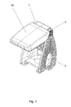
- Fig. 1 an axonometric view of the adjustable armrest
- Fig. 2 an axonometric view of the parts of the adjustable armrest in the partially disassembled state
- Fig. 3 an axonometric view of the parts of the adjustable armrest in the disassembled state
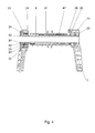
- Fig. 4 the shaft with the locking mechanism in section
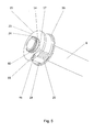
- Fig. 5 an axonometric view of the driver with the recess and detent
- Fig. 6 an axonometric view of the driver with the recess and detent in partial section
- Fig. 7 an axonometric view of the socket
- Fig. 8 the side view of the locking mechanism in the locked position
- Fig. 9 the side view of the locking mechanism in the unlocked position
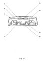
- Fig. 10 the side view of the locking mechanism in the locked position in section
- Fig. 11 the side view of the locking mechanism in the unlocked position in section
- Fig. 12 showing the cushion with arm in section.
- the adjustable armrest on an advantageous plastic-like carrier 1 in the upper part of an open lifting lug 2 and a closed lifting lug 3 is formed.
- the opened lifting lug 2 has a pair of opposing locking slots 4 ( FIG. Fig. 3 ), and further a securing recess 5 .
- the closed lifting lug 3 is formed by a ratchet wheel 6 with the internal toothing 7 , which is injected into a plastic carrier 1 during production.
- the shaft 8 is mounted with the locking mechanism 9 .
- an arm 10 is secured with guide slots 11 , on which the pad 12 is slidably mounted.
- the shaft 8 has a threaded cylindrical skirt 13 at one end and a grooved skirt 14 at the second end.
- the driver 15 (FIG. Fig. 5 ) Is pressed, having an enclosure of the driver 16 and further comprises a recess 17 in the pivot on the fixed pin 18, the ratchet wheel is mounted with external toothing 20 nineteenth
- In the recess 17 ( Fig. 6 ) is an opening of the spring of the catch 21 is formed, in which the detent spring 22 is arranged, through which the catch 19 radially from the center of rotation of the pad 12 in the internal toothing 7 of the ratchet wheel 6 (Fig. Fig.
- the bushing 28 having two opposed locking projections 29 which sink into the pair of opposed locking slots 4 and a locking clip 30 with which the socket 28 is clipped into the securing recess 5 , whereby the locking of the shaft 8 is secured in the axial direction.
- the bushing 26 has a cam skirt 56 (FIG. Fig. 2 ) on. This is designed to allow advancement of the cushion 12 at top dead center and avoid collision of the rear cushion with parts of the rear of the center console.
- a detent spring 33 and locking ball 34 is inserted in the opening of the locking spring 24 .
- the actuating ring 36 is provided with a slot 37 and an actuating lug 38 .
- the operating lug 38 of the actuating ring 36 moves in the angular recess 39 which is formed in the plastic carrier 1 and delimited by the front end surface 41 and the rear end surface 42 .
- the slot 37 of the actuating ring 36 is formed by a radial groove 43 and an oblique start 44 .
- the actuating ring 36 is mounted on the cylindrical part of the shaft 45 , in which groove is a locking ring 40 which holds the actuating ring 36 .
- a locking pin 46 is further fixedly mounted, which is guided with its second end in the slot 37 of the actuating ring 36 .
- a metal strut 47 is also attached on the shaft 8 .
- the metal strut 47 forms with the shaft 8 and the fixed driver 15 a welding group, which is injected after assembly in the plastic arm 10 , in which guide grooves 11 are formed.
- the cushion 12 is slidably mounted, which has a displaceable support member 48 , cushion support 49 and the foam filling 50 with respect to 51 ( Fig.2 ).
- the displaceable support member 48 has opposite sliding segments 52 and a silicone brake 53 .
- the arm 10 further includes an upper and lower cover 54 , 55 .
- the adjustable armrest has at least four height-locked positions of the pad 12 and corresponds to the number of teeth of the ratchet mechanism.
- To lock the locking mechanism 9 whose function from the FIG. 8, 9 . 10 and 11 can be seen.
- the catch 19 is taken.
- the locking of the locking mechanism 9 takes place after the lastzanarret istswolf when the pivoting or for pressing the catch 19 by the start of the locking pin 46 on the inclined start 44 of the radial groove 43, which is caused by the halting of the actuating ring 36 , the actuating lug 38th is supported on the front end surface 41 in the angular recess 39 of the plastic carrier 1 before top dead center of the adjustable armrest.
- the actuating ring 36 In the movement of the arm 10 with the pad 12 to the bottom dead center is driven by the radial force generated by the pressure of the locking spring 33 on the locking ball 34 , the actuating ring 36 , in which with the locking pin 46, the detent 19 is in position, where she passes with a margin on the internal teeth 7 of the ratchet wheel 6 . Only before the bottom dead center of the actuating ring 36 is stopped and the catch 19 is positioned with the locking pin 46 in the oblique start 44 of the radial groove 43 in the position where repeated movement of the arm 10 with the pad 12 up to impress its outer teeth 20 through the detent spring 22 takes place in the internal toothing 7 of the ratchet wheel 6 .
Landscapes
- Engineering & Computer Science (AREA)
- Aviation & Aerospace Engineering (AREA)
- Transportation (AREA)
- Mechanical Engineering (AREA)
- Seats For Vehicles (AREA)
Applications Claiming Priority (1)
| Application Number | Priority Date | Filing Date | Title |
|---|---|---|---|
| CZ20090693A CZ2009693A3 (cs) | 2009-10-21 | 2009-10-21 | Polohovatelná loketní opera |
Publications (2)
| Publication Number | Publication Date |
|---|---|
| EP2314475A2 true EP2314475A2 (fr) | 2011-04-27 |
| EP2314475A3 EP2314475A3 (fr) | 2017-12-27 |
Family
ID=43514093
Family Applications (1)
| Application Number | Title | Priority Date | Filing Date |
|---|---|---|---|
| EP10466026.1A Withdrawn EP2314475A3 (fr) | 2009-10-21 | 2010-10-20 | Accoudoir réglable |
Country Status (2)
| Country | Link |
|---|---|
| EP (1) | EP2314475A3 (fr) |
| CZ (1) | CZ2009693A3 (fr) |
Cited By (2)
| Publication number | Priority date | Publication date | Assignee | Title |
|---|---|---|---|---|
| WO2012171509A3 (fr) * | 2011-06-15 | 2013-05-23 | Skoda Auto A.S. | Accoudoir, en particulier accoudoir réglable pour véhicules automobiles |
| WO2014090736A1 (fr) * | 2012-12-12 | 2014-06-19 | Bayerische Motoren Werke Aktiengesellschaft | Accoudoir pivotant, en particulier accoudoir central pour un véhicule automobile |
Family Cites Families (4)
| Publication number | Priority date | Publication date | Assignee | Title |
|---|---|---|---|---|
| GB2023710A (en) * | 1977-10-18 | 1980-01-03 | Uop Inc | Locking seat hinges |
| DE10220651A1 (de) * | 2002-05-08 | 2003-11-27 | Seeber Ag & Co Kg | Scharnier, insbesondere für ein Kraftfahrzeug |
| DE20214711U1 (de) * | 2002-09-23 | 2004-02-19 | Seeber Ag & Co. Kg | Auf einem Träger abgestützter Deckel |
| JP2006340817A (ja) * | 2005-06-08 | 2006-12-21 | Calsonic Kansei Corp | アームレスト構造 |
-
2009
- 2009-10-21 CZ CZ20090693A patent/CZ2009693A3/cs unknown
-
2010
- 2010-10-20 EP EP10466026.1A patent/EP2314475A3/fr not_active Withdrawn
Non-Patent Citations (1)
| Title |
|---|
| None |
Cited By (2)
| Publication number | Priority date | Publication date | Assignee | Title |
|---|---|---|---|---|
| WO2012171509A3 (fr) * | 2011-06-15 | 2013-05-23 | Skoda Auto A.S. | Accoudoir, en particulier accoudoir réglable pour véhicules automobiles |
| WO2014090736A1 (fr) * | 2012-12-12 | 2014-06-19 | Bayerische Motoren Werke Aktiengesellschaft | Accoudoir pivotant, en particulier accoudoir central pour un véhicule automobile |
Also Published As
| Publication number | Publication date |
|---|---|
| CZ2009693A3 (cs) | 2011-05-04 |
| EP2314475A3 (fr) | 2017-12-27 |
Similar Documents
| Publication | Publication Date | Title |
|---|---|---|
| DE102015110114B4 (de) | Kraftbetriebene Sitzanordnung | |
| EP2525995B1 (fr) | Système de ferrures pour un siège automobile | |
| EP3310639B1 (fr) | Colonne de direction muni d'un dispositif de fixation électromécanique | |
| DE202012102159U1 (de) | Lenksäule für ein Kraftfahrzeug | |
| EP3099526A1 (fr) | Dispositif de réglage de dossier et siège de véhicule équipé d'un dispositif de réglage de dossier | |
| DE102007030028A1 (de) | Dreheinstellmechanismus | |
| DE102018200187A1 (de) | Armlehnenanordnung für einen Kraftfahrzeugsitz | |
| EP2464539B1 (fr) | Ferrure de verrouillage pour un siege de vehicule automobile | |
| EP3915829B1 (fr) | Ferrure de siège de véhicule et siège de véhicule | |
| DE102016224952A1 (de) | Sicherheitsgurtaufroller | |
| DE102012222983B4 (de) | Verschwenkbare Armlehne, insbesondere Mittelarmlehne für ein Kraftfahrzeug | |
| EP3911553B1 (fr) | Colonne de direction pour un véhicule automobile | |
| DE4235078C2 (de) | Verstellbeschlag mit Freischwenkeinrichtung für die Rückenlehne von Fahrzeugsitzen, insbesondere Kraftfahrzeugsitzen | |
| EP2314475A2 (fr) | Accoudoir réglable | |
| DE102022103377A1 (de) | Fahrzeugsitzbeschlag und Fahrzeugsitz | |
| EP3710334B1 (fr) | Colonne de direction pour un véhicule automobile | |
| EP2255994B1 (fr) | Accoudoir réglable | |
| DE102009037819A1 (de) | Beschlag für einen Fahrzeugsitz | |
| DE102007041495B3 (de) | Kopfstütze für einen Fahrzeugsitz und Antriebseinrichtung | |
| DE102011016053B4 (de) | Verstellbeschlag mit einem reduzierten Antriebsmoment | |
| DE102011119674A1 (de) | Lehneneinstellbeschlag mit einer Montageposition | |
| DE102022117694B3 (de) | Interieurbauteil für ein fahrzeug | |
| DE102011107249A1 (de) | Verstellvorrichtung für ein verstellbares Komfortelement eines Kraftfahrzeugs | |
| DE102018202199A1 (de) | Beschlaganordnung mit Blockiereinrichtung | |
| DE202008009745U1 (de) | Betätigungseinrichtung zum Entriegeln einer Sitzrückenlehne |
Legal Events
| Date | Code | Title | Description |
|---|---|---|---|
| PUAI | Public reference made under article 153(3) epc to a published international application that has entered the european phase |
Free format text: ORIGINAL CODE: 0009012 |
|
| AK | Designated contracting states |
Kind code of ref document: A2 Designated state(s): AL AT BE BG CH CY CZ DE DK EE ES FI FR GB GR HR HU IE IS IT LI LT LU LV MC MK MT NL NO PL PT RO RS SE SI SK SM TR |
|
| AX | Request for extension of the european patent |
Extension state: BA ME |
|
| PUAL | Search report despatched |
Free format text: ORIGINAL CODE: 0009013 |
|
| AK | Designated contracting states |
Kind code of ref document: A3 Designated state(s): AL AT BE BG CH CY CZ DE DK EE ES FI FR GB GR HR HU IE IS IT LI LT LU LV MC MK MT NL NO PL PT RO RS SE SI SK SM TR |
|
| AX | Request for extension of the european patent |
Extension state: BA ME |
|
| RIC1 | Information provided on ipc code assigned before grant |
Ipc: B60N 2/46 20060101AFI20171120BHEP Ipc: B60N 2/68 20060101ALI20171120BHEP |
|
| STAA | Information on the status of an ep patent application or granted ep patent |
Free format text: STATUS: THE APPLICATION HAS BEEN WITHDRAWN |
|
| 18W | Application withdrawn |
Effective date: 20180628 |