EP2314771A2 - Montants pour variateurs acoustiques et barrière acoustique associée - Google Patents
Montants pour variateurs acoustiques et barrière acoustique associée Download PDFInfo
- Publication number
- EP2314771A2 EP2314771A2 EP10425336A EP10425336A EP2314771A2 EP 2314771 A2 EP2314771 A2 EP 2314771A2 EP 10425336 A EP10425336 A EP 10425336A EP 10425336 A EP10425336 A EP 10425336A EP 2314771 A2 EP2314771 A2 EP 2314771A2
- Authority
- EP
- European Patent Office
- Prior art keywords
- upright
- fins
- lateral surface
- array
- main body
- Prior art date
- Legal status (The legal status is an assumption and is not a legal conclusion. Google has not performed a legal analysis and makes no representation as to the accuracy of the status listed.)
- Withdrawn
Links
Images


Classifications
-
- E—FIXED CONSTRUCTIONS
- E01—CONSTRUCTION OF ROADS, RAILWAYS, OR BRIDGES
- E01F—ADDITIONAL WORK, SUCH AS EQUIPPING ROADS OR THE CONSTRUCTION OF PLATFORMS, HELICOPTER LANDING STAGES, SIGNS, SNOW FENCES, OR THE LIKE
- E01F8/00—Arrangements for absorbing or reflecting air-transmitted noise from road or railway traffic
- E01F8/0005—Arrangements for absorbing or reflecting air-transmitted noise from road or railway traffic used in a wall type arrangement
- E01F8/0023—Details, e.g. foundations
-
- E—FIXED CONSTRUCTIONS
- E01—CONSTRUCTION OF ROADS, RAILWAYS, OR BRIDGES
- E01F—ADDITIONAL WORK, SUCH AS EQUIPPING ROADS OR THE CONSTRUCTION OF PLATFORMS, HELICOPTER LANDING STAGES, SIGNS, SNOW FENCES, OR THE LIKE
- E01F8/00—Arrangements for absorbing or reflecting air-transmitted noise from road or railway traffic
- E01F8/0005—Arrangements for absorbing or reflecting air-transmitted noise from road or railway traffic used in a wall type arrangement
- E01F8/0011—Plank-like elements
Definitions
- the present invention relates to an upright for acoustic barriers, the use thereof and the corresponding acoustic barrier.
- the present invention finds application in the field of construction, with the purpose of acoustically isolating an environment from the noise caused by road, rail, or other kinds of traffic originating from an adjacent or proximate environment.
- Known acoustic barriers may be "panel” type, otherwise known as artificial, or "embankment” type, otherwise known as natural.
- All known artificial barriers entail the presence of sound-absorbing panels supported by a support structure.
- the support structure is defined by two uprights constituted by IPE or HEB beams, whose conformation favours the insertion of the panels and the sound construction of the barrier.
- IPE (or HBE) beams are the typical beams having I-shaped (or H-shaped) cross section, which define to channels into which the panels are inserted by sliding from the top downwards.
- the beams are anchored to the ground, using a log bolt or other system, so that they are aligned and that each channel of a beam faces the respective channel of the next beam.
- the two channels serve as a track for the panels, which are introduced from the top and made to slide downwards for such a number as to reach the desired height.
- Prior art panels may be of different types, and they generally comprise a plurality of superposed layers of materials with different sound-absorbing characteristics.
- panels may comprise layers of perforated plate, mineral wool, concrete, polycarbonate, wood or other materials.
- panels of the same type have noise-proofing properties that change with thickness, and in particular with the number of sound-absorbing layers in use.
- the conformation of the aforesaid uprights entails the use of the aforementioned multi-layer panels, generally prefabricated, obtained by placing different materials side by side until reaching the thickness required by the size of the channel.
- the channel is dimensioned in accordance with the environmental factors relating to the entire area of utilisation and consequently all uprights used in the same area are of the same type.
- this does not allow to differentiate on site the acoustic performance of the barrier in the individual installation sectors, unless one has a priori knowledge of its exact sound characteristics, because the uprights allow only to position panels with predetermined thickness.
- said uprights entail the use of high-weight panels requiring appropriate machinery for lifting and mounting.
- the empty thickness is filled by an appropriate spacer, e.g. a second C-shaped steel section bar.
- the technical task of the present invention is to propose an upright for acoustic barriers and an acoustic barrier that overcome the aforementioned drawbacks of the prior art.
- an object of the present invention is to make available an upright for acoustic barriers that enables to optimize acoustic absorption and isolation in its different sectors of installation, even without having a priori knowledge of their exact sound characteristics.
- an additional object of the present invention is to propose an acoustic barrier that is easy to mount and has high performance, i.e. it is able to remain efficient even in winter and to adapt to areas with varied sound characteristics.
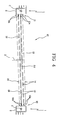
- the upright 1 comprises a main body 2 having a prevalent direction of development "A".
- the main body 2 is a substantially longitudinal body which in use is meant to protrude from the ground.
- the upright 1 comprises an anchoring body fastened to the main body 2, preferably at a lower portion 2a of the main body 2.
- the anchoring body is anchored to the ground, using a log bolt or another system, or to another upright 1 to enable the main body 2 to maintain an erect position and support the acoustic barrier.
- the main body 2 comprises a first 3 and a second lateral surface 4.
- said first 3 and second lateral surface 4 are substantially opposite.
- first 3 and the second lateral surface 3 are connected to each other by a third lateral surface 5.
- the third lateral surface 5 connects the first one 3 to the second lateral surface 4 at respective ends 3a, 4a thereof.
- the main body 2 also comprises a fourth lateral surface 6 that connects the first lateral surface 3 to the second lateral surface 4.
- the fourth lateral surface 6 connects the first lateral surface 3 to the second lateral surface 4 at additional ends 3b, 4b thereof, opposite to the aforesaid ends 3a, 4a.
- each of the lateral surfaces 3, 4, 5, 6 is defined by substantially planar wall 7, 8, 9,10.
- the main body 2 presents a polygonal closed and hollow cross section, combining excellent torsional strength and a limited mass of the upright 1.
- cross section means a section perpendicular to the prevalent direction of development "A" of the main body 2.
- the first lateral surface 3 presents a first array 11 of fins 11 a that develop away from the first lateral surface 3 along substantially parallel directions and with concurrent orientation.
- the second lateral surface 4 presents a second array 12 of fins 12a that develop away from the second lateral surface 4 along substantially parallel directions and with concurrent orientation.
- first 11 and the second array 12 present each at least three fins 11a, 12a, substantially equidistant from each other, in such a way as to define at least two mutually parallel channels 13 for receiving sound absorbing panels 14.
- the first 11 and the second array 12 present four fins 11a, 12a in such a way as to define three channels 13, allowing to increase the number of panels 14 that can be inserted and consequently a greater number of combination between them.
- each fin 11a, 12a develops longitudinally throughout the longitudinal extension of the main body 2.
- this enables to obtain channels 13 for receiving the sound-absorbing panels 14 that guide each panel 14 from an upper position of insertion to a final position, lower than the position of insertion.
- the first 3 and the second lateral surface 4 present a first portion 3c, 4c and a second portion 3d, 4d adjacent to the first portion 3c, 4c.
- the first portion 3c of the first lateral surface 3 is occupied by the first array 11 of fins 11 a, whilst the second portion 3d of the first lateral surface 3 is free of the fins 11 a.
- the first portion 4c of the second lateral surface 4 is occupied by the second array 12 of fins 12a, whilst the second portion 4d of the second lateral surface 4 is free of the fins 12a.
- the first lateral surface 3 is opposite to the second lateral surface 4.
- first portion 3c of the first lateral surface 3 is at least partly opposite to the second portion 4d of the second lateral surface 4.
- the second portion 3d of the first lateral surface 3 is at least in part opposite to the first portion 4c of the second lateral surface 4.
- each fin 11a of the first array 11 is positioned symmetrically relative to a corresponding fin 12a of the second array 12 relative to a central longitudinal axis "B" of the main body.
- Said central longitudinal axis "B” develops along the prevalent direction of development "A" of the main body and, more specifically, it defines the centre "C" from which the alignment of two successive uprights is measured.
- the fins 11a of the first array 11 are substantially parallel to the fins 12a of the second array 12.
- both the fins 11a of the first array 11 and the fins 12a of the second array 12 are inclined by an angle "W” relative to a transverse axis of orientation "D" of the main body 2.
- transverse axis of orientation D means an axis that is substantially perpendicular to the prevalent direction of development "A" of the main body 2 and that intercepts two opposite and aligned points lying on the first 3 and on the second lateral surface 4.
- this enables to obtain the mounting of sound-absorbing panels 14 that are inclined relative to a direction of alignment of the uprights 1.
- the angle of inclination "W" is between 0.5 and 10 degrees.
- the angle of inclination "W" of the fins 11a, 12a is between 1.5 and 2.5 degrees.
- each fin presents at least one longitudinal notch 16 that defines a housing seat of a gasket.
- the uprights 1 of the present invention are made of aluminium to reduce their weight and facilitate its transportability.
- the present invention further relates to an acoustic barrier 17 constructed through the use of a plurality of uprights 1.
- the acoustic barrier 17 comprises at least two uprights 1 aligned in such a way that each channel 13 defined by the first array 11 of fins 11 a of an upright 1 faces a respective channel 13 defined by the second array 12 of fins 12a of the next upright 1.
- the acoustic barrier 17 comprises at least one panelling 14 made of sound-absorbing material inserted between a channel 13 of an upright and the respective channel 13 of the next upright.
- an operator can insert a panelling 14 for each pair of mutually facing channels 13 of two successive uprights 1 obtaining a series of multiple parallel panellings between an upright 1 and the next one.
- the number of channels 13 is equal to the number of fins 11 a, 12a minus one
- the number of panellings 14 that can be inserted by the operator between two successive uprights 1 is between one and the number of fins 11 a, 12a of a same array 11,12 minus one.
- said direction of alignment "E" is the line joining the two centres "C" of the two successive uprights 1.
- the panellings 14 are inclined by an angle "X" between 0.5 and 10 degrees.
- the panellings 14 are inclined by an angle "X" between 1.5 and 2.5 degrees.
- this enables to better disperse the sound waves reflected by the acoustic barrier 17.
- the direction of alignment "E" coincides with the transverse axis of orientation "D" of the upright.
- the thickness of the fins 11 a, 12a between two parallel panellings 14 defines an air gap 18 between a panelling 14 and the other, preventing their contact.
- the thickness of the air gap 18 is closely linked with the absorption of the sound wavelengths in the area of use.
- the presence in the air gap 18 allows to prevent the surfaces of the panellings 14 from freezing during the winter and the consequent occlusion of their porosity, which entails a substantial loss of efficiency of the acoustic barrier 17.
- the panellings 14 used are mainly made of Celenit®, a material composed by mineralised wood fibres and cement serving as binder, coupled with other high-density materials to optimize acoustic characteristics.
- Celenit® can be coupled are, for example, Fermacell® and Acquapanel®, depending on the applications and on the desired acoustic characteristics.
- the upright 1 is able to receive multiple panellings 14 set side by side, the operator can use all these types of panel in combination to adapt the barriers to the sound characteristics of the area of use.
- the panellings 14 are divided into multiple panels 19 made of sound absorbing material aligned in the channels 13 of the upright 1 in such a number as to occlude the gap that is created between one upright 1 and the next one.
- this allows to use panellings 14 divided into lighter, more easily handled panels 19.
- said panels 19 are substantially planar and they have two dimensions of prevalent development.
- a first dimension of prevalent development corresponds to the width of the panelling 14, i.e. to the distance between an upright 1 and the next one.
- a second dimension of prevalent development is variable according to the type of panel 19.
- the second dimension of prevalent development is linked to the weight of the panel 19 and to the length of the upright 1.
- said reinforcements are mounted using through holes or the like.
- locking elements 20 are used which are fastened to an upper portion of both uprights 1. More specifically, said locking elements 20 are brackets 20a that are positioned between one upright and the next one, above the last panel 19 of the panelling 14, to prevent the protrusion of said panel 14 from the appropriate channel 13.
- said brackets 20a have semi-cylindrical shape with length equal to the distance between the centres "C" of two successive uprights 1.
- the invention achieves the proposed objects and it provides important advantages.
- the presence of fins that define multiple channels for receiving the panellings allows to differentiate the sound-absorbing properties of the barriers according to the installation sectors by changing the number of panellings used or by changing their order.
- the presence of the fins allows to maintain the various panellings distanced from each other from an air gap, fundamental for sound absorption and for preventing the degradation of the efficiency of the acoustic barrier during the winter months.
- studying the thickness of the fins according to the area of utilization it is possible to obtain an air gap that allows the absorption of the most frequent sound waves in the area.
- the presence of multiple channels allows, for equal necessary sound-absorbing properties, a greater ease of handling of the panellings because, in the present invention, weight is subdivided into multiple parallel panellings and, unlike in the prior art, it is not concentrated in a single element.
- the inclination of the panellings allows to obtain a better dispersion of the sound waves reflected by the barrier, and consequently it favours the optimisation of their performance.
Landscapes
- Engineering & Computer Science (AREA)
- Architecture (AREA)
- Civil Engineering (AREA)
- Structural Engineering (AREA)
- Life Sciences & Earth Sciences (AREA)
- Sustainable Development (AREA)
- Building Environments (AREA)
- Devices Affording Protection Of Roads Or Walls For Sound Insulation (AREA)
- Electromechanical Clocks (AREA)
Applications Claiming Priority (1)
| Application Number | Priority Date | Filing Date | Title |
|---|---|---|---|
| ITRM2009A000542A IT1396273B1 (it) | 2009-10-20 | 2009-10-20 | Montante per barriere acustiche e relativa barriera acustica. |
Publications (2)
| Publication Number | Publication Date |
|---|---|
| EP2314771A2 true EP2314771A2 (fr) | 2011-04-27 |
| EP2314771A3 EP2314771A3 (fr) | 2014-03-26 |
Family
ID=42153829
Family Applications (1)
| Application Number | Title | Priority Date | Filing Date |
|---|---|---|---|
| EP10425336.4A Withdrawn EP2314771A3 (fr) | 2009-10-20 | 2010-10-19 | Montants pour variateurs acoustiques et barrière acoustique associée |
Country Status (2)
| Country | Link |
|---|---|
| EP (1) | EP2314771A3 (fr) |
| IT (1) | IT1396273B1 (fr) |
Cited By (11)
| Publication number | Priority date | Publication date | Assignee | Title |
|---|---|---|---|---|
| CN107476211A (zh) * | 2017-09-29 | 2017-12-15 | 正升环境科技股份有限公司 | 一种屏障体无骨架的声屏障 |
| WO2020228845A3 (fr) * | 2020-07-28 | 2021-06-10 | 苏州讯如电子科技有限公司 | Appareil d'isolation acoustique et de réduction du bruit |
| CN114687305A (zh) * | 2022-04-26 | 2022-07-01 | 浙江交工集团股份有限公司 | 一种可叠合自锁声屏障结构 |
| CN115928618A (zh) * | 2022-11-23 | 2023-04-07 | 兰州交通大学 | 一种基于四复合十字型原胞的轨道交通声屏障 |
| CN116182954A (zh) * | 2023-03-13 | 2023-05-30 | 上海环境节能工程股份有限公司 | 一种用于声屏障屏体的监控系统 |
| WO2023114497A1 (fr) * | 2021-12-16 | 2023-06-22 | Onx, Inc. | Assemblage de cloisons modulaires acoustiquement absorbantes |
| US11795680B2 (en) | 2021-02-23 | 2023-10-24 | Renu, Inc. | Method and arrangement for constructing and interconnecting prefabricated building modules |
| US11873251B1 (en) | 2023-02-17 | 2024-01-16 | Onx, Inc. | Concrete composition for use in construction and methods of applying the same |
| DK202300144A1 (en) * | 2023-02-20 | 2024-08-30 | Tonax As | Panels for a partition wall or wall, and a system of such panels |
| US12094667B2 (en) | 2019-02-15 | 2024-09-17 | Onx, Inc. | Digital signaling device for signaling an electrical switch |
| US12244133B2 (en) | 2019-06-13 | 2025-03-04 | Onx, Inc. | Solid state circuit breaker |
Family Cites Families (5)
| Publication number | Priority date | Publication date | Assignee | Title |
|---|---|---|---|---|
| IT1293307B1 (it) * | 1997-07-09 | 1999-02-16 | Dieselbox Sa | Barriera antirumore a pannelli trasparenti,dotata di caratteristiche fonoisolanti e fonoassorbenti |
| FR2780075B1 (fr) * | 1998-06-19 | 2001-08-10 | Bernard Nakul | Ecrans anti-bruit et pare-vent presentes sous forme d'elements prets a monter |
| FR2783542B1 (fr) * | 1998-09-22 | 2001-06-22 | Pierre Verdiere | Poteaux en profiles reconstitues pour ecrans acoustiques constitues de panneaux |
| JP4121946B2 (ja) * | 2001-06-07 | 2008-07-23 | テレズィゴロジー インク | 調整装置及び建築部材 |
| ITPG20060027A1 (it) * | 2006-04-03 | 2007-10-04 | Vincenzo Tognaccini | Pannello fonoassorbente-fonoisolante-trasparente (p.f.f.t.)per realizzare barriere antirumore stradali o ferroviarie |
-
2009
- 2009-10-20 IT ITRM2009A000542A patent/IT1396273B1/it active
-
2010
- 2010-10-19 EP EP10425336.4A patent/EP2314771A3/fr not_active Withdrawn
Non-Patent Citations (1)
| Title |
|---|
| None |
Cited By (13)
| Publication number | Priority date | Publication date | Assignee | Title |
|---|---|---|---|---|
| CN107476211A (zh) * | 2017-09-29 | 2017-12-15 | 正升环境科技股份有限公司 | 一种屏障体无骨架的声屏障 |
| US12094667B2 (en) | 2019-02-15 | 2024-09-17 | Onx, Inc. | Digital signaling device for signaling an electrical switch |
| US12244133B2 (en) | 2019-06-13 | 2025-03-04 | Onx, Inc. | Solid state circuit breaker |
| WO2020228845A3 (fr) * | 2020-07-28 | 2021-06-10 | 苏州讯如电子科技有限公司 | Appareil d'isolation acoustique et de réduction du bruit |
| US11795680B2 (en) | 2021-02-23 | 2023-10-24 | Renu, Inc. | Method and arrangement for constructing and interconnecting prefabricated building modules |
| US12410602B2 (en) | 2021-02-23 | 2025-09-09 | Onx, Inc. | Method and arrangement for constructing and interconnecting prefabricated building modules |
| WO2023114497A1 (fr) * | 2021-12-16 | 2023-06-22 | Onx, Inc. | Assemblage de cloisons modulaires acoustiquement absorbantes |
| CN114687305A (zh) * | 2022-04-26 | 2022-07-01 | 浙江交工集团股份有限公司 | 一种可叠合自锁声屏障结构 |
| CN115928618A (zh) * | 2022-11-23 | 2023-04-07 | 兰州交通大学 | 一种基于四复合十字型原胞的轨道交通声屏障 |
| US11873251B1 (en) | 2023-02-17 | 2024-01-16 | Onx, Inc. | Concrete composition for use in construction and methods of applying the same |
| DK202300144A1 (en) * | 2023-02-20 | 2024-08-30 | Tonax As | Panels for a partition wall or wall, and a system of such panels |
| DK182270B1 (en) * | 2023-02-20 | 2026-01-29 | Tonax As | A partition wall system for open offices, divided offices, or meeting rooms |
| CN116182954A (zh) * | 2023-03-13 | 2023-05-30 | 上海环境节能工程股份有限公司 | 一种用于声屏障屏体的监控系统 |
Also Published As
| Publication number | Publication date |
|---|---|
| ITRM20090542A1 (it) | 2011-04-21 |
| IT1396273B1 (it) | 2012-11-16 |
| EP2314771A3 (fr) | 2014-03-26 |
Similar Documents
| Publication | Publication Date | Title |
|---|---|---|
| EP2314771A2 (fr) | Montants pour variateurs acoustiques et barrière acoustique associée | |
| US5426267A (en) | Highway and airport sound barriers | |
| CA2650172C (fr) | Systeme de ponts a pieds evases en beton precontraint | |
| US8733050B2 (en) | Compressive force transmitting connection element | |
| JP7462031B2 (ja) | コンクリート床版、コンクリート床版要素、ならびにコンクリート床版及びコンクリート床版要素を製造する方法 | |
| CN104594175B (zh) | 一种现代拱式竹质桥梁及其施工方法 | |
| RU2519314C1 (ru) | Несъемная опалубка | |
| KR100876679B1 (ko) | 교량용 방음 구조 및 그 시공방법 | |
| CN217896921U (zh) | 一种钢结构用双向密肋空腔楼盖模块 | |
| CN210658733U (zh) | 一种建筑装配式预制板 | |
| CN217517915U (zh) | 一种钢结构用双向密肋空腔楼盖模块 | |
| BRPI0921510B1 (pt) | elemento de placa de concreto protendido | |
| CN111075104A (zh) | 竹材与混凝土结合的墙板及其建造方法 | |
| NZ533319A (en) | Building system | |
| CN212656456U (zh) | 一种预制墙构件及其连接结构 | |
| AU2011101647A4 (en) | Mortarless masonry | |
| KR102351079B1 (ko) | 조립식 방음벽 | |
| CN104611997B (zh) | 一种具有减振降噪功能的分散支撑轨道结构 | |
| US20130295318A1 (en) | Reversible, thermo-acoustic panel for reversible, variable-geometry formwork | |
| CN213710226U (zh) | 一种风道分隔结构 | |
| RU2296198C2 (ru) | Сборная стеновая панель | |
| RU76656U1 (ru) | Связевая плита-распорка (варианты), узел соединения связевых плит-распорок (варианты) и рамно-связевый или связевый каркас сборного или сборно-монолитного здания со связевыми плитами-распорками | |
| KR20120066298A (ko) | 수직 기둥구조체를 이용한 개비온 방음벽 | |
| KR101188934B1 (ko) | 턱맞춤형 pc 보, 이를 구비한 pc 조립체 및 이를 이용한 pc 조립방법 | |
| EP1899543A1 (fr) | Assemblage de maçonnerie a l'epreuve des tremblements de terre |
Legal Events
| Date | Code | Title | Description |
|---|---|---|---|
| PUAI | Public reference made under article 153(3) epc to a published international application that has entered the european phase |
Free format text: ORIGINAL CODE: 0009012 |
|
| AK | Designated contracting states |
Kind code of ref document: A2 Designated state(s): AL AT BE BG CH CY CZ DE DK EE ES FI FR GB GR HR HU IE IS IT LI LT LU LV MC MK MT NL NO PL PT RO RS SE SI SK SM TR |
|
| AX | Request for extension of the european patent |
Extension state: BA ME |
|
| RIN1 | Information on inventor provided before grant (corrected) |
Inventor name: MITTERER, WITTFRIDA Inventor name: ZANINI, ALESSANDRO |
|
| PUAL | Search report despatched |
Free format text: ORIGINAL CODE: 0009013 |
|
| AK | Designated contracting states |
Kind code of ref document: A3 Designated state(s): AL AT BE BG CH CY CZ DE DK EE ES FI FR GB GR HR HU IE IS IT LI LT LU LV MC MK MT NL NO PL PT RO RS SE SI SK SM TR |
|
| AX | Request for extension of the european patent |
Extension state: BA ME |
|
| RIC1 | Information provided on ipc code assigned before grant |
Ipc: E01F 8/00 20060101AFI20140219BHEP Ipc: E04H 17/16 20060101ALI20140219BHEP |
|
| STAA | Information on the status of an ep patent application or granted ep patent |
Free format text: STATUS: THE APPLICATION IS DEEMED TO BE WITHDRAWN |
|
| 18D | Application deemed to be withdrawn |
Effective date: 20140927 |