EP2314827A2 - Appareil et procédé pour faciliter la connexion et la déconnexion d'éléments - Google Patents
Appareil et procédé pour faciliter la connexion et la déconnexion d'éléments Download PDFInfo
- Publication number
- EP2314827A2 EP2314827A2 EP11151012A EP11151012A EP2314827A2 EP 2314827 A2 EP2314827 A2 EP 2314827A2 EP 11151012 A EP11151012 A EP 11151012A EP 11151012 A EP11151012 A EP 11151012A EP 2314827 A2 EP2314827 A2 EP 2314827A2
- Authority
- EP
- European Patent Office
- Prior art keywords
- torque
- assembly
- engaging
- frame
- tubular
- Prior art date
- Legal status (The legal status is an assumption and is not a legal conclusion. Google has not performed a legal analysis and makes no representation as to the accuracy of the status listed.)
- Ceased
Links
Images


Classifications
-
- E—FIXED CONSTRUCTIONS
- E21—EARTH OR ROCK DRILLING; MINING
- E21B—EARTH OR ROCK DRILLING; OBTAINING OIL, GAS, WATER, SOLUBLE OR MELTABLE MATERIALS OR A SLURRY OF MINERALS FROM WELLS
- E21B19/00—Handling rods, casings, tubes or the like outside the borehole, e.g. in the derrick; Apparatus for feeding the rods or cables
- E21B19/16—Connecting or disconnecting pipe couplings or joints
- E21B19/161—Connecting or disconnecting pipe couplings or joints using a wrench or a spinner adapted to engage a circular section of pipe
-
- E—FIXED CONSTRUCTIONS
- E21—EARTH OR ROCK DRILLING; MINING
- E21B—EARTH OR ROCK DRILLING; OBTAINING OIL, GAS, WATER, SOLUBLE OR MELTABLE MATERIALS OR A SLURRY OF MINERALS FROM WELLS
- E21B19/00—Handling rods, casings, tubes or the like outside the borehole, e.g. in the derrick; Apparatus for feeding the rods or cables
- E21B19/16—Connecting or disconnecting pipe couplings or joints
- E21B19/161—Connecting or disconnecting pipe couplings or joints using a wrench or a spinner adapted to engage a circular section of pipe
- E21B19/163—Connecting or disconnecting pipe couplings or joints using a wrench or a spinner adapted to engage a circular section of pipe piston-cylinder actuated
-
- E—FIXED CONSTRUCTIONS
- E21—EARTH OR ROCK DRILLING; MINING
- E21B—EARTH OR ROCK DRILLING; OBTAINING OIL, GAS, WATER, SOLUBLE OR MELTABLE MATERIALS OR A SLURRY OF MINERALS FROM WELLS
- E21B19/00—Handling rods, casings, tubes or the like outside the borehole, e.g. in the derrick; Apparatus for feeding the rods or cables
- E21B19/18—Connecting or disconnecting drill bit and drilling pipe
Definitions
- the present invention relates to an apparatus and method for facilitating connecting and disconnecting members, such as, but not limited to threaded members such as casing, tubing, pipe, or drill pipe.
- connecting and disconnecting members such as, but not limited to threaded members such as casing, tubing, pipe, or drill pipe.
- threaded members such as casing, tubing, pipe, or drill pipe.
- One particular type of apparatus for connecting and disconnecting tubulars is commonly referred to as an iron roughneck.
- a drill bit is arranged on the end of a drill string and is rotated to bore the borehole.
- the drill string comprises a string of tubulars known as drill pipe sections.
- a drill pipe section comprises an upper and lower end. The upper end is provided with an enlarged section having a female thread, known as the box end; and the lower end is provided with an upstand and a male, known as the pin end.
- Sections of drill pipe are connected into stands of two or three sections. This may be carried out away from well centre using a mouse hole located in a floor of a drilling rig platform. The stand is then moved from the mouse hole to well centre and connected to a string of drill pipe in the well.
- a spinner To accomplish the connection between drill pipe, whether in the form of a section, stand or string, was carried out with two tools: a spinner; and a torque wrench.
- a pin of a section or stand of drill pipe is lowered into the box of a section or string retained in a mouse hole or well centre.
- the section or stand of drill pipe is lifted in an elevator to the muse hole or well centre.
- the pin end of the section or stand of drill pipe is lowered into the box of the drill pipe held in the mouse hole or well centre.
- the spinner is then removed and the torque wrench is offered up to the drill pipe.
- a back-up tong is used to inhibit the pipe retained in the mousehole or well centre from moving during torquing and may be used during spinning.
- the tong is activated to rotate the drill pipe section or stand and torque the connection to a required torque.
- the torque wrench and back-up tong are then removed from the drill pipe.
- An apparatus known as an iron roughneck combines a spinner with a tong and back-up tong.
- the box and the upstand "shoulder", such that, upon torquing the joint, a face of the upstand and a face of the box meet and there is a sharp rise in torque required to turn the upper drill pipe relative to the lower.
- This type of joint normally requires less than forty-five degrees of turn for the torquing step after the spinning step.
- some connections do not have shoulders and are continuous threads, such as Hydril Wedge Thread type connections.
- a string of pipe is lowered into the well in much the same way as for the drill string.
- the string is sometimes referred to as a tool string rather than a drill string.
- tubulars are used in the construction and maintenance of an oil or gas well, such as casing.
- Casing is usually screwed in single sections at the well centre and lowered into the well. The casing is then hung from the top of the well and may be cemented in place.
- Other tubulars known as liner is screwed together and lowered into the well. The liner is hung from the bottom of a section of casing and may be cemented in place.
- Downhole tools may also be connected into any of a: drill string; tool string; casing; or liner. These downhole tools may be connected with screwed threads and thus require spinning and torquing.
- FIG. 1 Various prior art iron roughnecks have a spinning wrench and a torque wrench mounted together on a carriage.
- a torque wrench For making or breaking threaded connections between two tubulars, for example joints of drill pipe, certain iron roughnecks have a torque wrench with two jaw levels.
- An upper jaw of the torque wrench is used to clamp onto a portion of an upper tubular, and a lower jaw clamps onto a portion of a lower tubular, for example upper and lower threadedly connected pieces of drill pipe. After clamping onto the connected tubulars, the upper and lower jaws are turned relative to each other to break a connection between the upper and lower tubulars.
- a spinning wrench mounted on the carriage above the torque wrench, engages the upper tubular and spins it until it is disconnected from the lower tubular.
- Certain prior art iron roughneck systems include a carriage for rolling on the surface of the rig floor along a predetermined path.
- a spinner and torque wrench are mounted for upward and downward movement relative to a carriage, for proper engagement with tubulars, and for tilting movement between a position in which their axis extends directly vertically for engagement with a vertical well pipe and a position in which the axis of the spinner and torque wrench is disposed at a slight angle to true vertical to engage and act against a pipe in an inclined mousehole.
- a spinner is movable vertically with respect to a torque wrench.
- non-shouldering connections including, but not limited to, wedge thread connections
- various prior art iron roughnecks are able to rotate a tubular through an arc ranging between about 28 degrees and 30 degrees.
- accurate full make up of a joint between two non-shouldering connections often requires that one tubular be rotated more than 30 degrees to form a good connection.
- these prior art systems have to unclamp, re-position jaws, clamp again, and rotate again (and, perhaps, do this several times).
- the prior art discloses a variety of tongs for use in wellbore operations, for example, but not limited to, as disclosed in and referred to in U.S. Patents 6,684,737 ; 6,971,283 ; 5,161,438 ; 5,159,860 ; 5,842,390 ; 5,245,877 ; 5,259,275 ; 5,390,568 ; 4,346,629 ; 5,044,232 ; 5,081,888 ; 5,167,173 ; 5,207,128 ; 5,409,280 ; 5,868,045 ; 6,966,385 ; 6,138,529 ; 4,082,017 ; 6,082,224 ; 6,213,216 ; 6,330,911 ; 6,668,684 ; 6,752,044 ; 6,318,214 ; and 6,142,041 .
- Several prior art tongs employ two opposed grippers which apply forces to a tubular in such a manner that the tubular can be distorted or damaged.
- an apparatus for facilitating connecting or disconnecting a first member to a second member comprising a frame and first and second engaging assemblies, each having three movable die carriers and powered movement apparatus for moving the die carriers simultaneously and in synchronisation.
- the three die carriers of the first engaging assembly may disengage and engage at the same time or at different times to the three die carriers of the second engaging assembly.
- the second torque assembly is operated, the second rocker arm moves outwardly moving the first torque assembly on the other first arm towards the frame and rotating or moving the first engaging apparatus a first amount to rotate and preferably torque the connection.
- the other of the first torque assembly is operated to extend to rotate the first engaging apparatus to rotate and preferably torque the connection a second amount.
- the first engaging apparatus can be rotated by the combined amount the first and second torque assemblies. This is carried out in a compact space.
- the apparatus is easy to handle and easily handled by mechanical handling equipment which may be remotely operated.
- the apparatus further comprises a piloting apparatus such that the first engaging assembly is rotatable with respect to the frame.
- the apparatus further comprises a piloting apparatus such that the second engaging assembly is rotatable with respect to the frame.
- the apparatus can rotate a tubular through an arc of about sixty degrees in one operation.
- the first engaging assembly is arranged on top of the second engaging assembly and preferably, in line with each other, such that the first and second members can align.
- the rocker assembly comprises a top rocker arm pivotably mounted to the frame, and a bottom rocker arm pivotably mounted to the frame.
- the first torque assembly comprises at least one extendible member.
- the at least one extendible member comprises a piston and cylinder.
- the extendible member is telescopic.
- the extendible member is hydraulic although may be pneumatic or mechanical, such as a rack and pinion or interlocking chain.
- the first torque assembly comprises at least two extendible members.
- the first engaging assembly has a housing with a throat for receiving the first member, each of the at least two extendible members arranged on each side of said throat.
- the at least first and second arms of the rocker assembly are movable about a pin or point with respect to the frame, one of said extendible members is arranged on said first arm and the other of the extendible members is arranged on a further arm.
- the further arm is on an opposing side of the pin to the first arm.
- the other of the additional extendible member is operated to extend to rotate the first engaging apparatus a second amount.
- the first engaging apparatus can be rotated by twice the amount a single additional extendible member could.
- the first arm is pushed back the further arm is pushed forward.
- the second torque assembly comprises at least two extendible members.
- the second engaging assembly has a housing having a throat, each of the at least two extendible members arranged on each side of said throat.
- the second engaging assembly has a housing with a throat for receiving the second member, each of the at least two extendible members arranged on each side of said throat.
- at least first and second arms of the rocker assembly are movable about a pin or point with respect to the frame, one of said extendible members is arranged on said second arm and the other of the extendible members is arranged on a further arm.
- the further arm is on an opposing side of the pin to the second arm.
- the frame comprises first and second plates, the first and second engaging assemblies arranged between the plates.
- the apparatus further comprises at least one link for selectively linking or fixing the frame to one of the first and second engaging assemblies.
- the apparatus further comprises at least one spacer fixed between the first and second plates, wherein the at least one link is fixed at one end to the spacer.
- the at least one link is slidably arranged on the spacer.
- the spacer is a bar or rod.
- a spacer is arranged on each side of the throat of the frame and each spacer is provided with a link.
- the first and second engaging assemblies are substantially identical or mirror images of each other.
- the first and second engaging assemblies comprise a housing.
- the housing comprises a first plate, a second plate and at least one spacer.
- the at least one comprises a spacer clevis.
- the first plate has a projection.
- the projection is in the form of an arc.
- the frame comprises a throat, the projection guided by a wall defining the shape of the throat.
- the first or second engaging assemblies each have a throat formed in the housing Preferably, for receiving one of the first and second member.
- the first or second engaging assembly comprises a die carrier.
- the first or second engaging assembly comprises a die.
- the first or second engaging apparatus comprises a movement assembly for moving the die or die carrier, such that in use, the die or die carrier are movable towards the first or second member for engagement therewith.
- the movement assembly is also for retracting the die or die carrier, such that in use, the die or die carrier are movable away from the first or second member for disengagement therewith.
- the movement assembly comprises a piston and cylinder.
- the piston and cylinder is arranged to rotate on or about a pin. The amount of rotation is limited by the torque link as described below.
- the die or die carrier is movable on a torque arm, wherein in use, the torque arm is connected to the housing, such that torsional loads are at least partly taken through the torque arm to the housing.
- the die or die carrier is guided by at least one spacer.
- the at least one spacer transfers torsional loads to the housing.
- two spacers are arranged on either side of the die and/or die carrier to guide the die or die carrier on the extendible. It is preferable to use a die carrier, so that the die can be removed for cleaning or replaced periodically. However, it is not essential and that the die can be integral with its carrier or for there to be no carrier at all.
- three movement apparatus are arranged about the throat in the housing.
- the three movement apparatus are arranged to centre the first or second member in the first or second engagement assembly respectively.
- the dies and/or movable die carriers of each engaging assembly are equally spaced apart to reduce distortion of the first or second member as the member is engaged.
- the member is gripped. The grip is preferably sufficient to hold the weight of the first member and sufficient to withstand a large torque as it is transferred from the apparatus to the first member and the reaction to the second member.
- the apparatus comprises a spinner such that in use the spinner rotates one of said first and second members.
- the spinner rotates the first or second member relative to the other at a relatively high speed of rotation to a relatively low torque.
- the spinner is located above the frame and may be rigidly connected there to.
- the present invention also provides the apparatus of the present invention and comprises a carriage and/or spinner.
- the present invention also provides a drilling rig comprising an apparatus of the invention and a carriage for moving the apparatus towards and away from a threaded members to be connected or disconnected.
- the carriage is arranged on a post located in a floor.
- the post is rotatable, such that the carriage and the appartus can be swung into and from the well centre or mousehole or rathole.
- the drilling rig further comprises a console for communication with the apparatus for rotating a tubular member.
- the threaded members comprise any one of: drill pipe, casing, liner, perforated liner, drill bit, mud motor, collars, downhole pump, liner hanger assembly parts; well tools; monitoring tools; well cleaning tool, cementing tool, coiled tubing and coiled tubing tools.
- the present invention also provides a method for connecting or disconnecting a first member to a second member, the apparatus comprising a frame, a rocker assembly connected to the frame, the rocker assembly having at least first and second arms, a first engaging assembly for engaging the first member and a second engaging assembly for engaging a second member, the first engaging assembly and second engaging assembly connected to the frame, a first torque assembly arranged between the first engaging assembly and said first arm of the rocker assembly, a second torque assembly arranged between the second engaging assembly and said second arm of the rocker assembly, the second engaging assembly fixed to the frame, the method comprising the steps of engaging a second member with the second engaging assembly, engaging a first member with the first engaging assembly and activating the first or second torque assembly to rotate the first engaging assembly such that, in use, torque generated by the first torque apparatus reacts through the rocker assembly, to the second engaging assembly.
- the second engaging assembly is selectively fixed to the frame.
- the second torque assembly is operated, the second rocker arm moves outwardly moving the first torque assembly on the other first arm towards the frame and rotating or moving the first engaging apparatus a first amount to rotate and preferably torque the first member to the second member, the first torque assembly is operated to rotate the first engaging apparatus to rotate and preferably torque the first member to the second member.
- the first torque assembly comprises an extendible member and second assembly comprises an extendible member the method comprising the steps of operating the second torque assembly to extend to move the second rocker arm outwardly moving the first torque assembly on the other first arm towards the frame and rotating or moving the first engaging apparatus a first amount, operating the first torque assembly to extend to rotate the first engaging apparatus to rotate and preferably torque the connection a second amount.
- method further comprises the steps of disengaging the first engaging assembly from the first member and disengaging the second assembly from the second member.
- the method further comprises the steps of unfixing the second engaging assembly from the frame, fixing the first engaging assembly to the frame activating the first or second torque assembly to rotate the second engaging assembly such that, in use, torque generated by the first torque apparatus reacts through the rocker assembly, to the first engaging assembly.
- this is carried out with a link slideable along a rod forming part of the frame between engagement with the first and the second engaging assemblies.
- the apparatus can be used to torque connections by rotating a lower member rather than the upper member.
- This is particularly useful when connecting drill bits to the tubular member, such as drill pipe, casing, a collar, mud motor or other item located in the bottom hole assembly.
- This is also useful for attaching tools located at the end of tool strings.
- This is also useful for making up stands of drill pipe.
- the lower drill pipe held in a rotatable mouse hole in the rig floor can be rotated and the upper section of drill pipe held stationary. This may improve safety for rig hands above deck.
- the present invention also provides an apparatus and method for connecting or disconnecting a first member to a second member, the apparatus comprising a frame and first and second engaging assemblies and a means for selectively fixing one of the first and second engaging assemblies to the frame, such that the other of the first and second assemblies can rotate, advantageously, to torque the connection between the first and second members.
- the means comprises a link
- the frame comprises first and second plates having a spacer therebetween, the link attached to the spacer.
- either the upper or the lower engaging assembly is securable to a frame that houses the engaging assemblies so that either engaging assembly can be used to rotate a tubular.
- a system in accordance with the present invention is useful for connection making and breaking as well as for bit breaking.
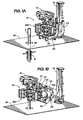
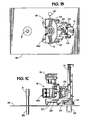
- FIGS 1A to 1D show a perspective view of part of an oil rig with an apparatus in accordance with the present invention, showing a first step in the operation of connecting drill pipe.
- the apparatus generally identified by reference numeral 10 is arranged on a carriage 20 which is movably connected for up/down vertical movement to a column 14 and which can also translate horizontally on a rig floor RF for movement toward and away from a drill pipe D of a drill string DS in a well W.
- the drill string D is at well centre.
- Support arms 22 each side of the apparatus 10 and two support arms 24 are pivotably connected at one end to a base 23 of the carriage 20 and at their other ends to a support 25.
- only one support arm is used or two arms in parallel are used.
- the dual arms move the spinner/wrench combination outwardly 60cm (24") from the column 14 which results in a 16.5cm (6.5”) rise vertically.
- the apparatus 10 in accordance with the present invention has a torque wrench 100 and a spinner 12 connected to a spin wrench carriage 27 and arranged on the support 25 and, are movable by a power mechanism PM toward and away from the column 14 by moving the support arms 22, 24.
- a known torque wrench may be used instead of a torque wrench in accordance with the present invention, for example instead of the torque wrench 100.
- Any suitable known spinner may be used, including, but not limited to, a spinner as disclosed in U.S. Patents 4,348,920 ; 6,776,070 ; 4,221,269 ; 5,660,087 ; 4,446,761 ; 3,892,148 ; 4,023,449 ; and as disclosed in the prior art references cited in these patents.
- the spinner 12 is movable up and down on the spin wrench carriage 25 toward and away from the torque wrench 100.
- a control console CS is shown schematically in Figure 1B .
- the console CS communicates by wire or wirelessly with the torque wrench 100, carriage 25 and spinner 12 and/or is located remotely from it.
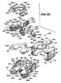
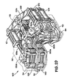
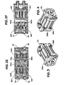
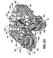
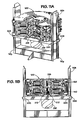
- FIGS 2A to 2F illustrate the torque wrench 100 in accordance with the present invention which has a frame 110 within which are a top jaw assembly 120 and a bottom jaw assembly 140. Gripping assemblies 170a, 170b, 170c, 180a, 180b, 180c in each jaw assembly are rotated by corresponding torque cylinders 101, 102, 103, 104. Each jaw assembly 120, 140 has torque cylinders 101, 102, 103, 104 for rotating a tubular gripped by the jaw assembly 120, 140. Torque cylinders 101 and 102 move upper gripping assemblies 170a, 170b, 170c, and torque cylinders 103, 104 move lower gripping assemblies 180a, 180b, 180c.
- a die carrier 127b is pivotably arranged on a proximal end of a torque link 128b.
- a distal end of the torque link 128b is pivotably connected to a spacer clevis 130b fixed between the upper and lower plates 122 and 124.
- the die carrier 127b is arranged in front of (and may be connected to) a rod of a clamping cylinder 126b.
- the rod is selectively extended or retracted, extending and retracting the die carrier 127b.
- the torque link 128b bears the load when the jaw assembly 120 is rotated or when it is stationary and is used to react forces from rotation of the lower jaw assembly 140, as described below.
- the rod of the power cylinder is thus substantially isolated from such loads.
- a shaft 101a of the torque cylinder 101 is pivotably connected to the spacer clevis 130b. Holes 128h in the torque link 128b receive pins 130p projecting from the spacer clevis 130b.
- a shaft 101a of the torque cylinder 101 has a hole 101h which receives a pin 130r projecting from the spacer clevis 130b for pivotably connecting the shaft 101a to the spacer clevis 130b.
- Each die carrier 127b, 127c is connected to each rod (for example the shaft 125b) that moves in and out of a power cylinder (see for example Figures 3 and 4 ).
- the die carriers 127b, 127c carry a die (or dies), which, in use, bite into a tubular allowing the force of the torque cylinders 101, 102, 103, 104 to impart a tangential load (torque) on the tubular.
- the external clamping cylinders 126a, 126b, 126c, 146a, 146b, 146c do not generate a tangential torque.
- the external clamping cylinders 126a, 126b, 126c, 146a, 146b, 146c push the dies into the tubular.
- the rear gripping assembly 170c is like the rear gripping assembly 180c.
- the rear gripping assembly 170c has a clamping cylinder 126a with a movable shaft 125a having connected thereto a die carrier 127c with a die (or dies) 132 held in place with a screw 131.
- the rear die carrier's movement is guided by abutting contact with edges 130e, 130f of the spacer clevis 130b and edges 130g, 130h of the spacer clevis 130c.
- Pins 126v on the top and the bottom of the power cylinder 126a (one pin 126v, the top pin, shown in Figure 2C ; the bottom pin is similarly located and projects from the bottom of the power cylinder 126a) project, respectively, into holes in the upper plate 122 and in the lower plate 124 for power cylinder 126a is fixed to the upper and lower plates 122, 124.
- the die carrier 127c bears the torque load on to the spacer clevis 130c when the jaw assembly 120 is rotated or when it is stationary and is used to react forces from rotation of the lower jaw assembly 140.
- the upper plate 122 has a groove 136 which receives centralizing pilot structure 134 which includes segment pieces 134a, 134b, and 134c connected to the upper jaw plate 122.
- the centralizing pilot structure 134 is used to maintain the top jaw assembly 120 in a desired central position in the frame 110.
- An upper part of the pieces 134a, 134b and 134c projects into a throat 116t of an upper frame plate 116 of the frame 110.
- Similar structure centres the lower jaw assembly 140, including a segment piece or pieces 144 (see Figure 2A ) and corresponding grooves in the lower jaw plate 124 and in an upper jaw plate 192 of the lower jaw assembly 140. Also a piece (or pieces) 145 in a groove 145a projecting down within a wall 118a of a throat 118t of a lower frame plate 118 of the wrench frame 110 centralize the lower jaw plate with respect to the wall 118a (as the pieces 134a - 134c centralize the upper jaw plate 122 with respect to the wall 116a).
- upper jaw assembly 120 can rotate with respect to the frame 110 and the lower jaw assembly 140.
- the lower jaw assembly 140 can rotate independently of upper jaw assembly 120.
- a rocker arm structure 108 has a main post 197 to which are connected an upper arm 195 and a lower arm 196.
- the torque cylinders 101, 102 are connected to the arm 195 and the torque cylinders 103, 104 are connected to the arm 196.
- Pins 198 are received in holes 115h in the upper and lower frame plates 116, 118 to pivotably secure the post 197 to the wrench frame 110.
- Rods 114 of the wrench frame 110 pass through holes 112h in grounding links 112.
- the grounding links 112 are movable up and down on the rods 114; rotatable with respect to the rods 114; and provide a connection between the wrench frame 110 and one of the jaw assemblies 120 or 140, for reasons described below.
- the grounding links 112 are pinned with pins 112p to corresponding spacer clevises 130b to selectively connect the lower jaw assembly 140 to the wrench frame 110; thus preventing the jaw assembly 140 from moving with respect to the wrench frame 110 and allowing the torque cylinders to turn an entire jaw plate with its gripping assemblies to rotate a tubular gripped by the gripping assemblies.
- the pin 112p passes through corresponding holes 130j in the spacer clevis 130b.
- the grounding links 112 can be disconnected from the spacer clevises 130b of the lower jaw assembly 140; raised on the rods 114; and then connected to the spacer clevises 130b of the upper jaw assembly 120 to render the upper jaw assembly 120 immobile with respect to the wrench frame 110 while freeing the lower jaw assembly 140 for movement.
- the wrench frame 110 has side members 117 and a rear member 113 connected to and between the upper and lower frame plate 116, 118 with mounting bodies 115 (top and bottom; one, shown, Figure 2C ) having the holes 115h.
- the wrench frame supports the jaw assemblies vertically, aligns their axes, and prevents rotation of either.
- the upper jaw assembly or the lower jaw assembly with the grounding links (which are attached to the lower jaw assembly in typical operations so only the upper jaw assembly can rotate). For bit breaking and similar operations, the grounding links are moved to the upper jaw assembly and connected thereto.
- a power cylinder PC (for example like the power cylinders used the upper and lower jaw assemblies 120, 140) has a port 199a through which fluid under pressure is provided to the power cylinder PC to extend a shaft 199d; a port 199b through which fluid is evacuated from the power cylinder to retract the power shaft 199d; and, optionally, a port 199c through which relatively high pressure fluid is provided, for example, in one aspect, at 350 bars (5000 psi), to increase clamping force and to further impress the dies onto a tubular.
- Typical known systems are used to provide fluid under pressure to the power cylinders PC of the jaw assemblies 120, 140.
- fluid under pressure for example ranging between 13 bars and 175 bars (200 and 2500 psi) is supplied from a fluid apparatus 10 or an existing source on, for example, a drilling rig), to a flow divider apparatus which has three positive displacement pumps, for example, but not limited to, three gear pumps, operated by a common shaft that provide power fluid to corresponding power cylinders.
- the apparatus 10 is initially positioned so that the rear power cylinders 126a and (not shown) and their dies contact a tubular to be gripped and rotated while one or both of the front dies of the front power cylinders may not yet be in contact with the tubular - and forces on the tubular from the three gripping assemblies of each jaw assembly 120, 140 are, therefore, unbalanced.
- the rear power cylinders 126a and (not shown) and their dies contact a tubular to be gripped and rotated while one or both of the front dies of the front power cylinders may not yet be in contact with the tubular - and forces on the tubular from the three gripping assemblies of each jaw assembly 120, 140 are, therefore, unbalanced.
- one or the other of the gripping assemblies moves so that the distances are equal and, in doing so, a tubular which is initially off-centre is pushed to the centre.
- the rear die then pushes off until the front dies contact the tubular, resulting in centering of the tub
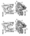
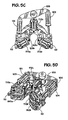
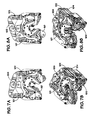
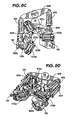
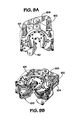
- FIGS 5A to 9B illustrate a variety of methods in accordance with the present invention which can be accomplished with a system 10 in accordance with the present invention and a torque wrench in accordance with the present invention, for example like the torque wrench 100.
- a system 10 in accordance with the present invention and a torque wrench in accordance with the present invention, for example like the torque wrench 100.
- the clamping forces of that jaw assembly's power cylinders are reacted through the power cylinders into the upper and lower jaw plates.
- Torquing loads on the dies are transmitted through the die carriers, torque links, spacer clevises, power cylinders and to the associated rocker arm, through the other rocker arm, to the jaw assembly at the other level. There are no external loads beyond the wrench frame.
- the upper and lower jaw assemblies 120, 140 of the torque wrench 100 are aligned and the die carriers are retracted.
- Fully stroking the upper and lower torque cylinders 101, 102, 103, 104 in the same direction results in the alignment of the upper and lower jaw assemblies 120, 140.
- This can be achieved in a first mode in which the torque cylinder 101 is retracted, the torque cylinder 102 is extended, the torque cylinder 103 is retracted, and the torque cylinder 104 is extended.
- this can be achieved in a second mode in which the torque cylinder 101 is extended, the torque cylinder 102 is retracted, the torque cylinder 103 is extended, and the torque cylinder 104 is retracted.
- Figures 7A and 7B illustrate the making of a threaded connected between two tubulars, (for example between two threadedly connected pieces of drill pipe, an upper piece and a lower piece).
- the spinner 12 (shown in Figure 1A ) spins the two pieces together to a certain extent without a final make-up torque so that the torque wrench's jaw assemblies 120, 140 can apply the final make-up torque.
- the spun-up connection is positioned so that the upper jaw assembly 120 can grip the upper drill pipe (not shown) and the lower jaw assembly 140 grips the lower piece (not shown).
- the lower jaw assembly 140 is grounded to the wrench frame 110 with the grounding links 112 and the upper jaw assembly 120 is rotated clockwise. This is accomplished by retracting torque cylinder 101, extending torque cylinder 102, extending torque cylinder 103, and retracting torque cylinder 104.
- the force applied to the pipe by the upper jaw assembly 120 is reacted to the lower jaw assembly 140 via the rocker arm apparatus 108.
- the torque reading drops to zero indicating make-up has not been effected.
- such a zero signal recycles and torquing would continue.
- An operator can then counter rotate prior to clamping onto the tubular for further rotation, i.e. the dies are retracted (unclamped) from engagement with the tubulars and stroked in the opposite direction, reclamped, and then torquing of the connection continues.
- FIGs 8A and 8B illustrate breaking a threaded connection between two threadedly connected tubulars (not shown), for example the two pieces of drill pipe made up in the method as shown in Figures 7A and 7B .
- the jaw assemblies 120, 140 are initially aligned as in Figure 5A and the threaded connection is received within the torque wrench 100.
- the torque cylinder 101 is extended, the torque cylinder 102 is retracted, the torque cylinder 103 is retracted, and the torque cylinder 104 is extended.
- the upper jaw plate 122 and its gripping assemblies 126a, 126b, 126c are rotated and the forces generated are reacted through the rocker apparatus 108 and to the lower jaw assembly 140 and its gripping assemblies.
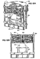
- Figures 10A, 10B , 11A and 11B illustrate an item breaking method in which a wellbore item, for example a bit or a connection for a device which is threadedly connected to a tubular member is disconnected therefrom.
- a wellbore item for example a bit or a connection for a device which is threadedly connected to a tubular member is disconnected therefrom.
- a breaking plate 204 is attached to the wrench frame 110a, for example part of the breaking plate 204 is inserted into an opening 206.
- the jaw assemblies 120, 140 of the torque wrench 100 are initially aligned as in Figure 5A .
- the grounding links 112 are switched to free the lower jaw assembly 140 and to connect the upper jaw assembly 120 to the wrench frame 110a so that the lower jaw assembly 140 can be used to break the connection.
- the threaded connection is received within the torque wrench (see Figures 10A, 10B ) and the die carriers of the lower jaw assembly are moved to grip the drill collar while the bit 200 (see Figures 10A and 10B ) is held within the breaking plate 204.
- the drill collar 202 is rotated counter clockwise (with the torque cylinder 103 extended, the torque cylinder 104 retracted, the torque cylinder 101 retracted, and the torque cylinder 102 extended).
- a bit or other item can be connected to a threaded tubular by reversing this method.
- a mud motor is disconnected from a drill collar by gripping the bottom of the mud motor with the system's lower jaw assembly and then rotating with the upper jaw assembly.
- the upper jaw 120 is pinned to the frame 110, thereby forcing the lower jaw 140 to rotate.
- the bit is installed in a torquing frame, which is grounded to the frame, thereby rotating the end of the mud motor into the stationary bit.
- FIGS 11A to 11C illustrate a system in accordance with the present invention like that of Figures 10A to 10C (like numerals indicate like parts) in which no breaking plate 204 is needed to make and break a connection between a bit and a tubular, for example a drill collar threadedly connected to the tubular.
- a PDC bit 210 has grip flats 212 which correspond to the shape of an opening 222 in a plate 220.
- the plate 220 is movable up and down on posts 110p of a wrench frame 110b (like the wrench frame 110a, Figure 10A ). Using pins 225, 226 the plate 220 is positioned as desired on the wrench frame 110b to accommodate bits of a particular height.
- an openable gate 230 provides access to the opening 222 (corresponding to grip flats on a bit) to accommodate larger bits.
- the PDC bit 210 is lowered into the opening 222 in the plate 220 and then the lower jaw assembly 140 of a torque wrench 100 grips the flats 212 of the bit.
- the upper jaw assembly 120 is then used to rotate a tubular, for example a drill collar, to make or break a connection with a threaded shaft 218 of the bit 210.
- a lip (not shown) on the plate 220 within the opening 222 may be used to support a bit.
- the bit is positioned in a breaker box or plate on top of a plate 220 (with any interior lip for a PDC bit removed) corresponding to the bit and the bit is torqued from below.
- a mud motor for example a rotor of a mud motor
- a torque wrench of a system in accordance with the present invention and a connection between the mud motor and a tubular threadedly connected thereto can be broken or made up.
- a jaw assembly of an apparatus in accordance with the present invention clamps on a tubular
- centralizing of the tubular with respect to the three dies of the die carriers and the biting of the dies into the tubular with equal force occurs.
- a rear die carrier and a front die carrier of an apparatus in accordance with the present invention contact and bite into a tubular.
- the flow of power fluid to each power cylinder associated with the dies is equal thereby causing the first two dies in contact with the tubular to push the tubular toward the third die as the third die also moves toward the tubular.
- Any tubular gripping system or apparatus disclosed herein may be incorporated into any suitable known tong or tubular gripper, including, but not limited to, the subject matter of the U.S. Patents listed by number above.
- Any tubular rotation system or apparatus disclosed herein may be incorporated into any suitable known tong or tubular gripper, including, but not limited to, the subject matter of the U.S. Patents listed by number above.
- both the upper and lower jaw assemblies can be unclamped from a lower tubular or the lower jaw assembly can be clamped to the lower tubular while the upper jaw assembly is unclamped.
- the present invention therefore, provides, in at least certain but not necessarily all embodiments, an apparatus for rotating a tubular, the apparatus having a frame; a rocker assembly connected to the frame, the rocker assembly including a top rocker arm pivotably mounted to the frame, and a bottom rocker arm pivotably mounted to the frame; top torque apparatus connected to the frame; upper gripper apparatus connected to the frame for gripping a primary tubular; lower gripper apparatus connected to the frame for gripping a secondary member; the upper gripper apparatus and lower gripper apparatus operable so that the lower gripper apparatus grips and holds the secondary member while the upper gripper apparatus grips and holds the primary tubular as the top torque apparatus is rotatable to rotate the primary tubular with respect to the secondary member; and torque generated by the top torque apparatus reacted through the upper gripper apparatus, through the top rocker arm, through the bottom rocker arm, and to the lower gripper apparatus.
- an apparatus for rotating a tubular including: a frame; a rocker assembly connected to the frame, the rocker assembly including a post, a top rocker arm, and a bottom rocker arm; the top rocker arm pivotably mounted to the post; the bottom rocker arm pivotably mounted to the post; top torque apparatus connected to the frame, including a first top torque cylinder apparatus and a second top torque cylinder apparatus; upper gripper apparatus connected to the frame for gripping a primary tubular, the upper gripper apparatus including a first upper gripper and a second upper gripper; the first upper gripper connected to the first top torque cylinder apparatus for movement thereby; the second upper gripper connected to the second top torque cylinder apparatus for movement thereby; bottom torque apparatus connected to the frame including a first bottom torque cylinder apparatus and a second bottom torque cylinder apparatus; lower gripper apparatus connected to the frame for gripping a secondary member, the lower gripper apparatus including a first lower gripper and a second lower
- Such an apparatus may have one or some, in any possible combination, of the following: the upper gripper apparatus including three movable die carriers spaced around the frame, each die carrier with dies for gripping a tubular, and the lower gripper apparatus including three movable die carriers spaced around the frame, each die carrier with dies for gripping a tubular; wherein the movable die carriers of each gripper apparatus are equally spaced apart to reduce distortion of a tubular gripped by the gripper apparatuses; wherein the three movable die carriers of each gripper apparatus are movable to facilitate centering of a tubular within the apparatus for rotating a tubular; wherein the bottom torque apparatus is operable to rotate the secondary member; at least one grounding link movably connected to the frame for selectively linking to the frame the upper gripper apparatus or the lower gripper apparatus; the three movable die carriers of the upper gripper apparatus are mounted between a first upper plate and a first lower plate, the first upper plate and the first lower plate each having a throat through which an item is movable for
- the present invention therefore, provides, in at least certain but not necessarily all embodiments, an apparatus for rotating a tubular, the apparatus having a frame; a rocker assembly connected to the frame, the rocker assembly including a post, a top rocker arm, and a bottom rocker arm; the top rocker arm pivotably mounted to the post; the bottom rocker arm pivotably mounted to the post; top torque apparatus connected to the frame, including a first top torque cylinder apparatus and a second top torque cylinder apparatus; upper gripper apparatus connected to the frame for gripping a primary tubular, the upper gripper apparatus including a first upper gripper and a second upper gripper; the first upper gripper connected to the first top torque cylinder apparatus for movement thereby; the second upper gripper connected to the second top torque cylinder apparatus for movement thereby; bottom torque apparatus connected to the frame including a first bottom torque cylinder apparatus and a second bottom torque cylinder apparatus; lower gripper apparatus connected to the frame for gripping a secondary member, the lower gripper apparatus including a first lower gripper and a second lower grip
- the present invention therefore, provides, in at least certain but not necessarily all embodiments, a method for rotating a primary tubular with respect to a secondary member, the method including gripping the primary tubular with an upper gripper apparatus of an apparatus for rotating a tubular in accordance with the present invention, gripping the secondary member with a lower gripper apparatus of an apparatus in accordance with the present invention, and with a top torque apparatus of an apparatus in accordance with the present invention rotating the primary tubular with respect to the secondary member.
Landscapes
- Engineering & Computer Science (AREA)
- Geology (AREA)
- Mining & Mineral Resources (AREA)
- Life Sciences & Earth Sciences (AREA)
- General Life Sciences & Earth Sciences (AREA)
- Fluid Mechanics (AREA)
- Mechanical Engineering (AREA)
- Environmental & Geological Engineering (AREA)
- Physics & Mathematics (AREA)
- Geochemistry & Mineralogy (AREA)
- Earth Drilling (AREA)
- Automatic Assembly (AREA)
- Current-Collector Devices For Electrically Propelled Vehicles (AREA)
- Manufacturing Of Electrical Connectors (AREA)
- Punching Or Piercing (AREA)
Applications Claiming Priority (3)
| Application Number | Priority Date | Filing Date | Title |
|---|---|---|---|
| US11/317,627 US7062991B1 (en) | 2005-12-23 | 2005-12-23 | Tubular connect/disconnect apparatus |
| US11/449,140 US7188547B1 (en) | 2005-12-23 | 2006-06-08 | Tubular connect/disconnect apparatus |
| EP06808777A EP1963611A1 (fr) | 2005-12-23 | 2006-11-24 | Appareil et procede pour faciliter le couplage et le decouplage d'elements |
Related Parent Applications (2)
| Application Number | Title | Priority Date | Filing Date |
|---|---|---|---|
| EP06808777.4 Division | 2006-11-24 | ||
| EP06808777A Division EP1963611A1 (fr) | 2005-12-23 | 2006-11-24 | Appareil et procede pour faciliter le couplage et le decouplage d'elements |
Publications (2)
| Publication Number | Publication Date |
|---|---|
| EP2314827A2 true EP2314827A2 (fr) | 2011-04-27 |
| EP2314827A3 EP2314827A3 (fr) | 2017-04-19 |
Family
ID=37684946
Family Applications (2)
| Application Number | Title | Priority Date | Filing Date |
|---|---|---|---|
| EP06808777A Withdrawn EP1963611A1 (fr) | 2005-12-23 | 2006-11-24 | Appareil et procede pour faciliter le couplage et le decouplage d'elements |
| EP11151012.9A Ceased EP2314827A3 (fr) | 2005-12-23 | 2006-11-24 | Appareil et procédé pour faciliter la connexion et la déconnexion d'éléments |
Family Applications Before (1)
| Application Number | Title | Priority Date | Filing Date |
|---|---|---|---|
| EP06808777A Withdrawn EP1963611A1 (fr) | 2005-12-23 | 2006-11-24 | Appareil et procede pour faciliter le couplage et le decouplage d'elements |
Country Status (5)
| Country | Link |
|---|---|
| US (2) | US7188547B1 (fr) |
| EP (2) | EP1963611A1 (fr) |
| CA (2) | CA2718014C (fr) |
| NO (2) | NO342265B1 (fr) |
| WO (1) | WO2007072071A1 (fr) |
Cited By (4)
| Publication number | Priority date | Publication date | Assignee | Title |
|---|---|---|---|---|
| WO2015031672A1 (fr) * | 2013-08-28 | 2015-03-05 | Hauk Thomas D | Combinaison de roue de tige de forage et de dispositif de clé de serrage |
| AU2012216863B2 (en) * | 2012-09-14 | 2015-11-19 | Metso Finland Oy | Head bolt tightening tool for a cone crusher head assembly |
| US9393678B2 (en) | 2012-09-14 | 2016-07-19 | Metso Minerals (France) S.A. | Head bolt tightening tool for a cone crusher head assembly |
| WO2025037987A1 (fr) * | 2023-08-17 | 2025-02-20 | Canrig Robotic Technologies As | Élément foreur en fer à actionneur rotatif |
Families Citing this family (63)
| Publication number | Priority date | Publication date | Assignee | Title |
|---|---|---|---|---|
| US7509722B2 (en) * | 1997-09-02 | 2009-03-31 | Weatherford/Lamb, Inc. | Positioning and spinning device |
| US7431550B2 (en) * | 2002-10-04 | 2008-10-07 | Technologies Alliance | Pipe handling apparatus for pick-up and lay-down machine |
| US7350587B2 (en) * | 2004-11-30 | 2008-04-01 | Varco I/P, Inc. | Pipe guide |
| US7552775B2 (en) * | 2005-05-02 | 2009-06-30 | Weatherford/Lamb, Inc. | Tailing in and stabbing device and method |
| US7926576B2 (en) * | 2006-03-27 | 2011-04-19 | Schlumberger Technology Corporation | Coiled tubing rig |
| US20080060818A1 (en) * | 2006-09-07 | 2008-03-13 | Joshua Kyle Bourgeois | Light-weight single joint manipulator arm |
| US20090211404A1 (en) * | 2008-02-25 | 2009-08-27 | Jan Erik Pedersen | Spinning wrench systems |
| US7841415B2 (en) * | 2007-03-22 | 2010-11-30 | National Oilwell Varco, L.P. | Iron roughneck extension systems |
| US7997166B2 (en) * | 2007-06-15 | 2011-08-16 | Longyear Tm, Inc. | Methods and apparatus for joint disassembly |
| US7699098B2 (en) * | 2007-08-08 | 2010-04-20 | Blohm & Voss Oil Tools, Llc | Apparatus for stabbing pipe when using an iron roughneck |
| US7997167B2 (en) * | 2007-08-30 | 2011-08-16 | Longyear Tm, Inc. | Clamping and breaking device |
| WO2009031166A1 (fr) * | 2007-09-03 | 2009-03-12 | Sgolastra & Giampaoli S.R.L. | Équipement utilisé pour dévisser des tiges de forage du type constitué d'une paire de presses superposées |
| US9297223B2 (en) | 2008-02-12 | 2016-03-29 | Warrior Rig Ltd. | Top drive with slewing power transmission |
| US8109179B2 (en) * | 2008-02-12 | 2012-02-07 | Allan Stewart Richardson | Power tong |
| US20090272235A1 (en) * | 2008-05-01 | 2009-11-05 | Joe Berry | Tubular handling system |
| EP2274498A2 (fr) * | 2008-05-12 | 2011-01-19 | Longyear TM, Inc. | Dispositif decouvert de vissage de tiges |
| US7849929B2 (en) * | 2008-05-12 | 2010-12-14 | Longyear Tm, Inc. | Drill rod spinner device |
| US20100050407A1 (en) * | 2008-08-28 | 2010-03-04 | Buck David A | Method of Repairing Tong Jaw |
| WO2011017610A1 (fr) * | 2009-08-06 | 2011-02-10 | Frank's International, Inc. | Appareil de jonction de tubulures |
| US20110214917A1 (en) * | 2009-09-12 | 2011-09-08 | Professional Wireline Rentals, Llc | Power Swivel Stand Having Pivoting Positioning Arms |
| CN102822442B (zh) * | 2010-01-15 | 2015-09-09 | 维米尔制造公司 | 钻机和钻孔方法 |
| WO2011133821A2 (fr) * | 2010-04-21 | 2011-10-27 | National Oilwell Varco, L.P. | Appareil pour suspendre une rame de puits de fond de trou |
| CN101832115B (zh) * | 2010-04-30 | 2013-04-17 | 中国地质大学(武汉) | 用于外平钻杆拧卸的大扭矩液压拧管机 |
| CN102031939B (zh) * | 2010-12-01 | 2013-01-23 | 武汉金地探矿机械有限公司 | 用于外平钻杆拧卸的可让开孔口的液压拧管机 |
| US8967278B2 (en) | 2011-01-19 | 2015-03-03 | Nabors Canada | Collar assembly for breaking tubing hanger connections |
| NO333115B1 (no) * | 2011-08-09 | 2013-03-04 | Robotic Drilling Systems As | Anordning ved aktivering av klembakker i en kontinuerlig roterende momenttang til bruk ved tiltrekking og apning av gjengeforbindelser |
| EP2753782B1 (fr) * | 2011-09-09 | 2016-05-18 | National Oilwell Varco Norway AS | Système de guidage et son procédé de fonctionnement |
| US9144894B2 (en) | 2011-11-11 | 2015-09-29 | Target Drilling, Inc. | Drill pipe breakout machine |
| GB2498190A (en) | 2012-01-04 | 2013-07-10 | Nat Oilwell Varco Lp | Apparatus and method for positioning and connecting equipment on a drilling rig |
| US9447645B2 (en) | 2012-03-29 | 2016-09-20 | Black Dog Industries Llc | Breakout wrench assemblies and methods |
| US8733213B2 (en) * | 2012-04-03 | 2014-05-27 | Rangeland Drilling Automation Inc. | Power tong apparatus |
| US20130340572A1 (en) * | 2012-06-21 | 2013-12-26 | Complete Production Services, Inc. | Long lateral completion system pipe tong and method of using the same |
| US9708860B2 (en) | 2012-06-21 | 2017-07-18 | Superior Energy Services-North America Services, Inc | Ground level rig and method |
| US9267328B2 (en) | 2012-06-21 | 2016-02-23 | Superior Energy Services-North America Services, Inc. | Methods for real time control of a mobile rig |
| US9540878B2 (en) | 2012-06-21 | 2017-01-10 | Superior Energy Services—North America Services, Inc | Method and apparatus for inspecting and tallying pipe |
| CN103132931B (zh) * | 2013-02-25 | 2015-12-09 | 吉林大学 | 一种铁钻工 |
| CN103132930B (zh) * | 2013-02-25 | 2016-06-08 | 吉林大学 | 一种铁钻工的旋扣装置 |
| US9452535B2 (en) | 2013-05-31 | 2016-09-27 | National Oilwell Varco, L.P. | Self-aligning pipe gripping assembly and method of making and using the same |
| US9366097B2 (en) * | 2013-11-25 | 2016-06-14 | Honghua America, Llc | Power tong for turning pipe |
| CN105874152B (zh) | 2013-12-30 | 2018-03-06 | 长年Tm公司 | 用于将钻杆移至和移出操作位置的钻杆处理系统 |
| US9551193B2 (en) | 2014-03-25 | 2017-01-24 | Schramm, Inc. | Drill pipe handling apparatus having improved pipe gripping mechanism |
| US10081991B2 (en) | 2014-11-05 | 2018-09-25 | Weatherford Technology Holdings, Llc | Modular adapter for tongs |
| NO340895B1 (no) * | 2014-12-19 | 2017-07-10 | Quality Technical Group As | Apparat og framgangsmåte for sammensetting og oppbrekking av borestrengelementer |
| KR101631960B1 (ko) * | 2015-06-03 | 2016-06-20 | 은광산업 주식회사 | 시추용 파이프의 체결 및 해체를 위한 토크 렌치 |
| KR101631965B1 (ko) * | 2015-06-03 | 2016-06-20 | 은광산업 주식회사 | 3-Roller 구조형 토크 렌치 시스템 |
| KR101691076B1 (ko) * | 2015-08-12 | 2016-12-29 | 삼성중공업 주식회사 | 드릴 비트 교체 장치 |
| AU2016379380B2 (en) | 2015-12-22 | 2021-10-21 | Boart Longyear Manufacturing And Distribution Inc. | Drill rod clamping system and methods of using same |
| AU2017200880B2 (en) * | 2016-02-12 | 2022-01-20 | Joy Global Surface Mining Inc | Mechanism for retaining bits on a blasthole drill |
| US10619429B2 (en) * | 2016-05-12 | 2020-04-14 | Odfjell Well Services Norway As | Integrated flush-mount spider and power-tong apparatus and method of use |
| US10337264B2 (en) * | 2016-11-21 | 2019-07-02 | Weatherford Technology Holdings, Llc | Movable tong assembly |
| CN106812481B (zh) * | 2017-02-22 | 2019-01-04 | 吉林大学 | 铁钻工旋扣机构 |
| US10808468B2 (en) | 2017-05-31 | 2020-10-20 | Forum Us, Inc. | Spinner tool with floating carriage device |
| US10808469B2 (en) * | 2017-05-31 | 2020-10-20 | Forum Us, Inc. | Wrench assembly with floating torque bodies |
| US10808470B2 (en) | 2017-05-31 | 2020-10-20 | Forum Us, Inc. | Spinner assembly with four bar linkage device |
| CN107386997B (zh) * | 2017-07-26 | 2018-12-21 | 西南石油大学 | 一种换钻头更换装置 |
| US10605016B2 (en) * | 2017-11-16 | 2020-03-31 | Weatherford Technology Holdings, Llc | Tong assembly |
| US11078733B2 (en) * | 2018-08-22 | 2021-08-03 | Weatherford Technology Holdings, Llc | Apparatus and methods for determining operational mode of tong assembly |
| CN109403892B (zh) * | 2018-09-19 | 2020-06-05 | 亨通海洋工程有限公司 | 一种钻机钻杆快速拆装工艺 |
| CN109332008B (zh) * | 2018-11-06 | 2020-12-01 | 岳欣 | 一种方便对试管进行固定的血液检测用离心机 |
| US11592346B2 (en) | 2020-02-26 | 2023-02-28 | Weatherford Technology Holdings, Llc | Multi-range load cell |
| US11136838B1 (en) | 2020-04-22 | 2021-10-05 | Weatherford Technology Holdings, Llc | Load cell for a tong assembly |
| CA3118648C (fr) * | 2020-05-20 | 2026-05-19 | Nabors Drilling Technologies Usa, Inc. | Cle dynamometrique |
| US12473784B1 (en) | 2025-01-02 | 2025-11-18 | TCI Casing Specialties, LLC | Casing pipe coupling systems and methods of coupling casing pipes |
Citations (33)
| Publication number | Priority date | Publication date | Assignee | Title |
|---|---|---|---|---|
| US3892148A (en) | 1974-08-01 | 1975-07-01 | Byron Jackson Inc | Adjustable power spinning tong |
| US4023449A (en) | 1975-02-18 | 1977-05-17 | Varco International, Inc. | Tool for connecting and disconnecting well pipe |
| US4082017A (en) | 1975-01-07 | 1978-04-04 | Eckel Manufacturing Co. | Power operated drill pipe tongs |
| US4221269A (en) | 1978-12-08 | 1980-09-09 | Hudson Ray E | Pipe spinner |
| US4346629A (en) | 1980-05-02 | 1982-08-31 | Weatherford/Lamb, Inc. | Tong assembly |
| US4348920A (en) | 1980-07-31 | 1982-09-14 | Varco International, Inc. | Well pipe connecting and disconnecting apparatus |
| US4446761A (en) | 1981-04-24 | 1984-05-08 | Varco International, Inc. | Pipe spinning tool |
| US4765401A (en) | 1986-08-21 | 1988-08-23 | Varco International, Inc. | Apparatus for handling well pipe |
| US5044232A (en) | 1988-12-01 | 1991-09-03 | Weatherford U.S., Inc. | Active jaw for a power tong |
| US5081888A (en) | 1988-12-01 | 1992-01-21 | Weatherford, U.S., Inc. | Apparatus for connecting and disconnecting threaded members |
| US5159860A (en) | 1991-04-12 | 1992-11-03 | Weatherford/Lamb, Inc. | Rotary for a power tong |
| US5161438A (en) | 1991-04-12 | 1992-11-10 | Weatherford/Lamb, Inc. | Power tong |
| US5167173A (en) | 1991-04-12 | 1992-12-01 | Weatherford/Lamb, Inc. | Tong |
| US5207128A (en) | 1992-03-23 | 1993-05-04 | Weatherford-Petco, Inc. | Tong with floating jaws |
| US5245877A (en) | 1991-03-12 | 1993-09-21 | Weatherford U.S., Inc. | Tong load cell assembly |
| US5259275A (en) | 1992-06-16 | 1993-11-09 | Weatherford/Lamb, Inc. | Apparatus for connecting and disconnecting threaded members |
| US5390568A (en) | 1992-03-11 | 1995-02-21 | Weatherford/Lamb, Inc. | Automatic torque wrenching machine |
| US5409280A (en) | 1993-09-03 | 1995-04-25 | Weatherford/Lamb, Inc. | Pipe clamp |
| US5660087A (en) | 1995-08-08 | 1997-08-26 | Rae; Donald David | Drill pipe spinner |
| US5842390A (en) | 1996-02-28 | 1998-12-01 | Frank's Casing Crew And Rental Tools Inc. | Dual string backup tong |
| US5868045A (en) | 1993-05-26 | 1999-02-09 | Hawk Industries, Inc. | Apparatus for making and breaking joints in drill pipe strings |
| US6082224A (en) | 1997-01-29 | 2000-07-04 | Weatherford/Lamb, Inc. | Power tong |
| US6138529A (en) | 1997-02-07 | 2000-10-31 | Weatherford/Lamb, Inc. | Apparatus for gripping a tubular member |
| US6142041A (en) | 1998-12-01 | 2000-11-07 | Buck; David A. | Power tong support assembly |
| US6213216B1 (en) | 1999-03-05 | 2001-04-10 | Tommie L Rogers | Snubbing unit tong apparatus |
| US6318214B1 (en) | 1998-12-01 | 2001-11-20 | David A. Buck | Power tong positioning apparatus |
| US6330911B1 (en) | 1999-03-12 | 2001-12-18 | Weatherford/Lamb, Inc. | Tong |
| US6668684B2 (en) | 2000-03-14 | 2003-12-30 | Weatherford/Lamb, Inc. | Tong for wellbore operations |
| US6684737B1 (en) | 1999-01-28 | 2004-02-03 | Weatherford/Lamb, Inc. | Power tong |
| US6752044B2 (en) | 2002-05-06 | 2004-06-22 | Frank's International, Inc. | Power tong assembly and method |
| US6776070B1 (en) | 1999-05-02 | 2004-08-17 | Varco I/P, Inc | Iron roughneck |
| US6966385B2 (en) | 2003-02-03 | 2005-11-22 | Eckel Manufacturing Co., Inc. | Tong positioning system and method |
| US6971283B2 (en) | 2002-09-12 | 2005-12-06 | National-Oilwell, L.P. | Jaw insert for gripping a cylindrical member and method of manufacture |
Family Cites Families (61)
| Publication number | Priority date | Publication date | Assignee | Title |
|---|---|---|---|---|
| US2453369A (en) | 1945-05-15 | 1948-11-09 | Donovan B Grable | Pipe tongs |
| US3021739A (en) | 1957-12-23 | 1962-02-20 | Joy Mfg Co | Hydraulically controlled and operated power tong |
| US3131586A (en) | 1960-05-11 | 1964-05-05 | Wilson John Hart | Mechanism for making up and breaking out screw threaded joints of drill stem and pipe |
| GB1087137A (en) | 1963-10-25 | 1967-10-11 | F N R D Ltd | Improvements relating to twist joints |
| BE757087A (fr) | 1969-12-03 | 1971-04-06 | Gardner Denver Co | Mecanisme de devissage de tiges de forage commande a distance |
| US3808916A (en) | 1970-09-24 | 1974-05-07 | Robbins & Ass J | Earth drilling machine |
| US3722331A (en) | 1971-06-21 | 1973-03-27 | Ipcur Inst De Proiectari Cerce | Torque-controlled pipe-thread tightener |
| US3796418A (en) | 1972-02-17 | 1974-03-12 | Byron Jackson Inc | Hydraulic pipe tong apparatus |
| US4069879A (en) | 1976-10-15 | 1978-01-24 | Brown Cicero C | Pipe handler |
| US4126348A (en) | 1977-05-05 | 1978-11-21 | Bj-Hughes, Inc. | Universal handling head for a pipe racker |
| US4128135A (en) | 1977-07-13 | 1978-12-05 | Gardner-Denver Company | Drill pipe handling mechanism |
| US4334444A (en) | 1978-06-26 | 1982-06-15 | Bob's Casing Crews | Power tongs |
| US4402239A (en) | 1979-04-30 | 1983-09-06 | Eckel Manufacturing Company, Inc. | Back-up power tongs and method |
| US4401000A (en) * | 1980-05-02 | 1983-08-30 | Weatherford/Lamb, Inc. | Tong assembly |
| US4445403A (en) * | 1982-03-29 | 1984-05-01 | Larry D. Kliewer | Power tongs |
| FR2526080A1 (fr) | 1982-04-30 | 1983-11-04 | Brissonneau & Lotz | Procede et dispositif de blocage et de liberation d'une tige de forage a axe sensiblement vertical |
| US4442892A (en) | 1982-08-16 | 1984-04-17 | Domenico Delesandri | Apparatus for stabbing and threading a safety valve into a well pipe |
| US5049020A (en) | 1984-01-26 | 1991-09-17 | John Harrel | Device for positioning and stabbing casing from a remote selectively variable location |
| US4648292A (en) | 1984-03-19 | 1987-03-10 | Joy Manufacturing Company | Tong assembly |
| US4649777A (en) | 1984-06-21 | 1987-03-17 | David Buck | Back-up power tongs |
| US4574664A (en) | 1984-07-23 | 1986-03-11 | Eckel Manufacturing Co., Inc. | Powered back-up tongs |
| US4603464A (en) | 1985-03-11 | 1986-08-05 | Hughes Tool Company | Stand jumping and stabbing guide device and method |
| US4667752A (en) | 1985-04-11 | 1987-05-26 | Hughes Tool Company | Top head drive well drilling apparatus with stabbing guide |
| US4712284A (en) | 1986-07-09 | 1987-12-15 | Bilco Tools Inc. | Power tongs with hydraulic friction grip for speciality tubing |
| US4843945A (en) | 1987-03-09 | 1989-07-04 | National-Oilwell | Apparatus for making and breaking threaded well pipe connections |
| US5000065A (en) | 1987-09-08 | 1991-03-19 | Martin-Decker, Inc. | Jaw assembly for power tongs and like apparatus |
| US4800968A (en) | 1987-09-22 | 1989-01-31 | Triten Corporation | Well apparatus with tubular elevator tilt and indexing apparatus and methods of their use |
| US4811635A (en) | 1987-09-24 | 1989-03-14 | Falgout Sr Thomas E | Power tong improvement |
| NO163973C (no) | 1988-04-19 | 1990-08-15 | Maritime Hydraulics As | Momenttanganordning. |
| US5092399A (en) | 1990-05-07 | 1992-03-03 | Master Metalizing And Machining Inc. | Apparatus for stabbing and threading a drill pipe safety valve |
| FR2679593B1 (fr) * | 1991-07-23 | 1997-04-25 | Gazel Anthoine G | Machine a visser et devisser, notamment pour train de tiges, d'une installation de forage. |
| US5294228A (en) | 1991-08-28 | 1994-03-15 | W-N Apache Corporation | Automatic sequencing system for earth drilling machine |
| US6082225A (en) | 1994-01-31 | 2000-07-04 | Canrig Drilling Technology, Ltd. | Power tong wrench |
| US5671961A (en) | 1995-10-13 | 1997-09-30 | Buck; David A. | Back-up power tongs |
| US5845549A (en) * | 1995-12-20 | 1998-12-08 | Frank's Casing Crew And Rental Tools, Inc. | Power tong gripping ring mechanism |
| FR2761683B1 (fr) * | 1997-04-02 | 1999-05-28 | Inst Francais Du Petrole | Procede de production d'ether et d'olefine a partir de coupe hydrocarbonee contenant au moins une olefine tertiaire par synthese puis decomposition d'ether comportant une premiere etape de purification d'olefine par fractionnement |
| US6536520B1 (en) | 2000-04-17 | 2003-03-25 | Weatherford/Lamb, Inc. | Top drive casing system |
| GB9718543D0 (en) | 1997-09-02 | 1997-11-05 | Weatherford Lamb | Method and apparatus for aligning tubulars |
| US6070500A (en) | 1998-04-20 | 2000-06-06 | White Bear Energy Serives Ltd. | Rotatable die holder |
| US6065372A (en) | 1998-06-02 | 2000-05-23 | Rauch; Vernon | Power wrench for drill pipe |
| US6116118A (en) | 1998-07-15 | 2000-09-12 | Wesch, Jr.; William E. | Gripping apparatus for power tongs and backup tools |
| US6223629B1 (en) | 1999-07-08 | 2001-05-01 | Daniel S. Bangert | Closed-head power tongs |
| US6814149B2 (en) | 1999-11-26 | 2004-11-09 | Weatherford/Lamb, Inc. | Apparatus and method for positioning a tubular relative to a tong |
| KR100747819B1 (ko) | 2000-01-13 | 2007-08-08 | 아케르 바르너 엠에이치 에이에스 | 수평 파이프 취급 장치 |
| NO311539B1 (no) | 2000-04-28 | 2001-12-03 | Hitec Asa | Anordning ved spinner |
| US6722231B2 (en) * | 2001-03-19 | 2004-04-20 | Hawk Industries, Inc. | Pipe make/break apparatus with gripping jaws and adjustable pipe spinner with oiling system |
| CA2487120A1 (fr) | 2002-05-30 | 2003-12-11 | Gray Eot, Inc. | Appareil de connexion et de deconnexion de tige de forage |
| US6994176B2 (en) | 2002-07-29 | 2006-02-07 | Weatherford/Lamb, Inc. | Adjustable rotating guides for spider or elevator |
| US6868923B2 (en) | 2002-08-30 | 2005-03-22 | The Regents Of The University Of California | Portable apparatus and method for assisting in the removal and emplacement of pipe strings in boreholes |
| US7114235B2 (en) | 2002-09-12 | 2006-10-03 | Weatherford/Lamb, Inc. | Automated pipe joining system and method |
| WO2004065753A1 (fr) * | 2003-01-14 | 2004-08-05 | Tt Technologies, Inc. | Dispositif et procede de prise de trepan |
| US6793021B1 (en) | 2003-02-03 | 2004-09-21 | Robert P. Fanguy | Screen table tong assembly and method |
| US7413398B2 (en) | 2003-04-01 | 2008-08-19 | Mccoy Corporation | Power tong positioner |
| US20040211297A1 (en) | 2003-04-23 | 2004-10-28 | Bangert Daniel S. | Tong piston and cylinder assembly |
| US7040411B2 (en) | 2003-05-02 | 2006-05-09 | National-Oilwell, L.P. | BOP handling system |
| US7017450B2 (en) | 2003-08-11 | 2006-03-28 | Bangert Daniel S | Tong jaw and a method for constructing the tong jaw |
| US7000502B2 (en) | 2003-09-05 | 2006-02-21 | National-Ollwell | Drillpipe spinner |
| US7000503B2 (en) | 2004-04-27 | 2006-02-21 | Mccoy Bros. Inc. | Support system for power tong assembly |
| US7121166B2 (en) | 2004-04-29 | 2006-10-17 | National-Oilwell, L.P. | Power tong assembly |
| US7013759B1 (en) | 2005-08-31 | 2006-03-21 | Access Oil Tools, Inc. | Apparatus for handling tubulars and method |
| US7062991B1 (en) * | 2005-12-23 | 2006-06-20 | Varco I/P, Inc. | Tubular connect/disconnect apparatus |
-
2006
- 2006-06-08 US US11/449,140 patent/US7188547B1/en not_active Expired - Lifetime
- 2006-11-24 CA CA2718014A patent/CA2718014C/fr active Active
- 2006-11-24 WO PCT/GB2006/050413 patent/WO2007072071A1/fr not_active Ceased
- 2006-11-24 EP EP06808777A patent/EP1963611A1/fr not_active Withdrawn
- 2006-11-24 EP EP11151012.9A patent/EP2314827A3/fr not_active Ceased
- 2006-11-24 CA CA2631665A patent/CA2631665C/fr active Active
-
2007
- 2007-03-10 US US11/716,987 patent/US7313986B2/en not_active Expired - Lifetime
-
2008
- 2008-05-20 NO NO20082267A patent/NO342265B1/no unknown
-
2018
- 2018-02-28 NO NO20180305A patent/NO348810B1/no unknown
Patent Citations (33)
| Publication number | Priority date | Publication date | Assignee | Title |
|---|---|---|---|---|
| US3892148A (en) | 1974-08-01 | 1975-07-01 | Byron Jackson Inc | Adjustable power spinning tong |
| US4082017A (en) | 1975-01-07 | 1978-04-04 | Eckel Manufacturing Co. | Power operated drill pipe tongs |
| US4023449A (en) | 1975-02-18 | 1977-05-17 | Varco International, Inc. | Tool for connecting and disconnecting well pipe |
| US4221269A (en) | 1978-12-08 | 1980-09-09 | Hudson Ray E | Pipe spinner |
| US4346629A (en) | 1980-05-02 | 1982-08-31 | Weatherford/Lamb, Inc. | Tong assembly |
| US4348920A (en) | 1980-07-31 | 1982-09-14 | Varco International, Inc. | Well pipe connecting and disconnecting apparatus |
| US4446761A (en) | 1981-04-24 | 1984-05-08 | Varco International, Inc. | Pipe spinning tool |
| US4765401A (en) | 1986-08-21 | 1988-08-23 | Varco International, Inc. | Apparatus for handling well pipe |
| US5044232A (en) | 1988-12-01 | 1991-09-03 | Weatherford U.S., Inc. | Active jaw for a power tong |
| US5081888A (en) | 1988-12-01 | 1992-01-21 | Weatherford, U.S., Inc. | Apparatus for connecting and disconnecting threaded members |
| US5245877A (en) | 1991-03-12 | 1993-09-21 | Weatherford U.S., Inc. | Tong load cell assembly |
| US5159860A (en) | 1991-04-12 | 1992-11-03 | Weatherford/Lamb, Inc. | Rotary for a power tong |
| US5161438A (en) | 1991-04-12 | 1992-11-10 | Weatherford/Lamb, Inc. | Power tong |
| US5167173A (en) | 1991-04-12 | 1992-12-01 | Weatherford/Lamb, Inc. | Tong |
| US5390568A (en) | 1992-03-11 | 1995-02-21 | Weatherford/Lamb, Inc. | Automatic torque wrenching machine |
| US5207128A (en) | 1992-03-23 | 1993-05-04 | Weatherford-Petco, Inc. | Tong with floating jaws |
| US5259275A (en) | 1992-06-16 | 1993-11-09 | Weatherford/Lamb, Inc. | Apparatus for connecting and disconnecting threaded members |
| US5868045A (en) | 1993-05-26 | 1999-02-09 | Hawk Industries, Inc. | Apparatus for making and breaking joints in drill pipe strings |
| US5409280A (en) | 1993-09-03 | 1995-04-25 | Weatherford/Lamb, Inc. | Pipe clamp |
| US5660087A (en) | 1995-08-08 | 1997-08-26 | Rae; Donald David | Drill pipe spinner |
| US5842390A (en) | 1996-02-28 | 1998-12-01 | Frank's Casing Crew And Rental Tools Inc. | Dual string backup tong |
| US6082224A (en) | 1997-01-29 | 2000-07-04 | Weatherford/Lamb, Inc. | Power tong |
| US6138529A (en) | 1997-02-07 | 2000-10-31 | Weatherford/Lamb, Inc. | Apparatus for gripping a tubular member |
| US6142041A (en) | 1998-12-01 | 2000-11-07 | Buck; David A. | Power tong support assembly |
| US6318214B1 (en) | 1998-12-01 | 2001-11-20 | David A. Buck | Power tong positioning apparatus |
| US6684737B1 (en) | 1999-01-28 | 2004-02-03 | Weatherford/Lamb, Inc. | Power tong |
| US6213216B1 (en) | 1999-03-05 | 2001-04-10 | Tommie L Rogers | Snubbing unit tong apparatus |
| US6330911B1 (en) | 1999-03-12 | 2001-12-18 | Weatherford/Lamb, Inc. | Tong |
| US6776070B1 (en) | 1999-05-02 | 2004-08-17 | Varco I/P, Inc | Iron roughneck |
| US6668684B2 (en) | 2000-03-14 | 2003-12-30 | Weatherford/Lamb, Inc. | Tong for wellbore operations |
| US6752044B2 (en) | 2002-05-06 | 2004-06-22 | Frank's International, Inc. | Power tong assembly and method |
| US6971283B2 (en) | 2002-09-12 | 2005-12-06 | National-Oilwell, L.P. | Jaw insert for gripping a cylindrical member and method of manufacture |
| US6966385B2 (en) | 2003-02-03 | 2005-11-22 | Eckel Manufacturing Co., Inc. | Tong positioning system and method |
Cited By (5)
| Publication number | Priority date | Publication date | Assignee | Title |
|---|---|---|---|---|
| AU2012216863B2 (en) * | 2012-09-14 | 2015-11-19 | Metso Finland Oy | Head bolt tightening tool for a cone crusher head assembly |
| US9393678B2 (en) | 2012-09-14 | 2016-07-19 | Metso Minerals (France) S.A. | Head bolt tightening tool for a cone crusher head assembly |
| WO2015031672A1 (fr) * | 2013-08-28 | 2015-03-05 | Hauk Thomas D | Combinaison de roue de tige de forage et de dispositif de clé de serrage |
| WO2025037987A1 (fr) * | 2023-08-17 | 2025-02-20 | Canrig Robotic Technologies As | Élément foreur en fer à actionneur rotatif |
| US12540517B2 (en) | 2023-08-17 | 2026-02-03 | Canrig Robotic Technologies As | Iron roughneck with rotary actuator |
Also Published As
| Publication number | Publication date |
|---|---|
| NO348810B1 (no) | 2025-06-10 |
| EP1963611A1 (fr) | 2008-09-03 |
| US7313986B2 (en) | 2008-01-01 |
| CA2631665C (fr) | 2011-10-04 |
| US20070193417A1 (en) | 2007-08-23 |
| US7188547B1 (en) | 2007-03-13 |
| WO2007072071A1 (fr) | 2007-06-28 |
| CA2718014A1 (fr) | 2007-06-28 |
| CA2631665A1 (fr) | 2007-06-28 |
| EP2314827A3 (fr) | 2017-04-19 |
| NO20082267L (no) | 2008-08-19 |
| NO20180305A1 (no) | 2018-08-19 |
| NO342265B1 (no) | 2018-04-30 |
| CA2718014C (fr) | 2013-02-12 |
Similar Documents
| Publication | Publication Date | Title |
|---|---|---|
| CA2631665C (fr) | Appareil et procede pour faciliter le couplage et le decouplage d'elements | |
| CN101346529B (zh) | 一种便于连接和断开部件的装置和方法 | |
| CA2798377C (fr) | Appareil et procede pour positionner un equipement de liaison sur un appareil de forage | |
| CN101611215B (zh) | 顶部驱动设备和移除与顶部驱动器连接的器件的方法 | |
| US7707914B2 (en) | Apparatus and methods for connecting tubulars | |
| US7055594B1 (en) | Pipe gripper and top drive systems | |
| RU2435929C2 (ru) | Способ и устройство для проведения операций в подземных буровых скважинах | |
| EP0199664A2 (fr) | Machine pour la manipulation de tiges de puits | |
| US6505531B2 (en) | Oil tool connection breaker and method | |
| WO2003102350A2 (fr) | Appareil de connexion et de deconnexion de tige de forage | |
| WO2008114064A1 (fr) | Appareil et procédé pour déplacer un équipement de liaison sur un appareil de forage | |
| EP1159508B1 (fr) | Appareil a cles a tiges d'un dispositif de forage pour intervention sous pression | |
| US20090211404A1 (en) | Spinning wrench systems | |
| EP3615763B1 (fr) | Appareil de forage comprenant un système de manipulation de support tubulaire | |
| WO1999010130A1 (fr) | Cle double pour tige de forage | |
| EP1819896B1 (fr) | Unite d'entrainement par le haut, dispositif de prise de tube et procede de forage de puits | |
| CA2714327A1 (fr) | Procede et dispositif de forage avec cuvelage |
Legal Events
| Date | Code | Title | Description |
|---|---|---|---|
| PUAI | Public reference made under article 153(3) epc to a published international application that has entered the european phase |
Free format text: ORIGINAL CODE: 0009012 |
|
| AC | Divisional application: reference to earlier application |
Ref document number: 1963611 Country of ref document: EP Kind code of ref document: P |
|
| AK | Designated contracting states |
Kind code of ref document: A2 Designated state(s): GB NL |
|
| PUAL | Search report despatched |
Free format text: ORIGINAL CODE: 0009013 |
|
| AK | Designated contracting states |
Kind code of ref document: A3 Designated state(s): GB NL |
|
| RIC1 | Information provided on ipc code assigned before grant |
Ipc: E21B 19/18 20060101ALI20170315BHEP Ipc: E21B 19/16 20060101AFI20170315BHEP |
|
| STAA | Information on the status of an ep patent application or granted ep patent |
Free format text: STATUS: REQUEST FOR EXAMINATION WAS MADE |
|
| 17P | Request for examination filed |
Effective date: 20170905 |
|
| RBV | Designated contracting states (corrected) |
Designated state(s): GB NL |
|
| STAA | Information on the status of an ep patent application or granted ep patent |
Free format text: STATUS: EXAMINATION IS IN PROGRESS |
|
| 17Q | First examination report despatched |
Effective date: 20171116 |
|
| STAA | Information on the status of an ep patent application or granted ep patent |
Free format text: STATUS: THE APPLICATION HAS BEEN REFUSED |
|
| 18R | Application refused |
Effective date: 20210305 |