EP2314867A2 - Darrieus-windrad mit vertikaler welle - Google Patents
Darrieus-windrad mit vertikaler welle Download PDFInfo
- Publication number
- EP2314867A2 EP2314867A2 EP09803186A EP09803186A EP2314867A2 EP 2314867 A2 EP2314867 A2 EP 2314867A2 EP 09803186 A EP09803186 A EP 09803186A EP 09803186 A EP09803186 A EP 09803186A EP 2314867 A2 EP2314867 A2 EP 2314867A2
- Authority
- EP
- European Patent Office
- Prior art keywords
- primary
- primary shaft
- shaft
- blades
- darrieus windmill
- Prior art date
- Legal status (The legal status is an assumption and is not a legal conclusion. Google has not performed a legal analysis and makes no representation as to the accuracy of the status listed.)
- Withdrawn
Links
Images



Classifications
-
- F—MECHANICAL ENGINEERING; LIGHTING; HEATING; WEAPONS; BLASTING
- F03—MACHINES OR ENGINES FOR LIQUIDS; WIND, SPRING, OR WEIGHT MOTORS; PRODUCING MECHANICAL POWER OR A REACTIVE PROPULSIVE THRUST, NOT OTHERWISE PROVIDED FOR
- F03D—WIND MOTORS
- F03D3/00—Wind motors with rotation axis substantially perpendicular to the air flow entering the rotor
- F03D3/06—Rotors
-
- F—MECHANICAL ENGINEERING; LIGHTING; HEATING; WEAPONS; BLASTING
- F03—MACHINES OR ENGINES FOR LIQUIDS; WIND, SPRING, OR WEIGHT MOTORS; PRODUCING MECHANICAL POWER OR A REACTIVE PROPULSIVE THRUST, NOT OTHERWISE PROVIDED FOR
- F03D—WIND MOTORS
- F03D3/00—Wind motors with rotation axis substantially perpendicular to the air flow entering the rotor
- F03D3/06—Rotors
- F03D3/061—Rotors characterised by their aerodynamic shape, e.g. aerofoil profiles
-
- F—MECHANICAL ENGINEERING; LIGHTING; HEATING; WEAPONS; BLASTING
- F03—MACHINES OR ENGINES FOR LIQUIDS; WIND, SPRING, OR WEIGHT MOTORS; PRODUCING MECHANICAL POWER OR A REACTIVE PROPULSIVE THRUST, NOT OTHERWISE PROVIDED FOR
- F03D—WIND MOTORS
- F03D3/00—Wind motors with rotation axis substantially perpendicular to the air flow entering the rotor
- F03D3/02—Wind motors with rotation axis substantially perpendicular to the air flow entering the rotor having a plurality of rotors
-
- F—MECHANICAL ENGINEERING; LIGHTING; HEATING; WEAPONS; BLASTING
- F03—MACHINES OR ENGINES FOR LIQUIDS; WIND, SPRING, OR WEIGHT MOTORS; PRODUCING MECHANICAL POWER OR A REACTIVE PROPULSIVE THRUST, NOT OTHERWISE PROVIDED FOR
- F03D—WIND MOTORS
- F03D3/00—Wind motors with rotation axis substantially perpendicular to the air flow entering the rotor
- F03D3/06—Rotors
- F03D3/062—Rotors characterised by their construction elements
-
- F—MECHANICAL ENGINEERING; LIGHTING; HEATING; WEAPONS; BLASTING
- F03—MACHINES OR ENGINES FOR LIQUIDS; WIND, SPRING, OR WEIGHT MOTORS; PRODUCING MECHANICAL POWER OR A REACTIVE PROPULSIVE THRUST, NOT OTHERWISE PROVIDED FOR
- F03D—WIND MOTORS
- F03D3/00—Wind motors with rotation axis substantially perpendicular to the air flow entering the rotor
- F03D3/06—Rotors
- F03D3/062—Rotors characterised by their construction elements
- F03D3/064—Fixing wind engaging parts to rest of rotor
-
- F—MECHANICAL ENGINEERING; LIGHTING; HEATING; WEAPONS; BLASTING
- F05—INDEXING SCHEMES RELATING TO ENGINES OR PUMPS IN VARIOUS SUBCLASSES OF CLASSES F01-F04
- F05B—INDEXING SCHEME RELATING TO WIND, SPRING, WEIGHT, INERTIA OR LIKE MOTORS, TO MACHINES OR ENGINES FOR LIQUIDS COVERED BY SUBCLASSES F03B, F03D AND F03G
- F05B2240/00—Components
- F05B2240/20—Rotors
- F05B2240/21—Rotors for wind turbines
- F05B2240/211—Rotors for wind turbines with vertical axis
- F05B2240/212—Rotors for wind turbines with vertical axis of the Darrieus type
-
- F—MECHANICAL ENGINEERING; LIGHTING; HEATING; WEAPONS; BLASTING
- F05—INDEXING SCHEMES RELATING TO ENGINES OR PUMPS IN VARIOUS SUBCLASSES OF CLASSES F01-F04
- F05B—INDEXING SCHEME RELATING TO WIND, SPRING, WEIGHT, INERTIA OR LIKE MOTORS, TO MACHINES OR ENGINES FOR LIQUIDS COVERED BY SUBCLASSES F03B, F03D AND F03G
- F05B2240/00—Components
- F05B2240/20—Rotors
- F05B2240/21—Rotors for wind turbines
- F05B2240/211—Rotors for wind turbines with vertical axis
- F05B2240/213—Rotors for wind turbines with vertical axis of the Savonius type
-
- F—MECHANICAL ENGINEERING; LIGHTING; HEATING; WEAPONS; BLASTING
- F05—INDEXING SCHEMES RELATING TO ENGINES OR PUMPS IN VARIOUS SUBCLASSES OF CLASSES F01-F04
- F05B—INDEXING SCHEME RELATING TO WIND, SPRING, WEIGHT, INERTIA OR LIKE MOTORS, TO MACHINES OR ENGINES FOR LIQUIDS COVERED BY SUBCLASSES F03B, F03D AND F03G
- F05B2240/00—Components
- F05B2240/20—Rotors
- F05B2240/21—Rotors for wind turbines
- F05B2240/211—Rotors for wind turbines with vertical axis
- F05B2240/214—Rotors for wind turbines with vertical axis of the Musgrove or "H"-type
-
- F—MECHANICAL ENGINEERING; LIGHTING; HEATING; WEAPONS; BLASTING
- F05—INDEXING SCHEMES RELATING TO ENGINES OR PUMPS IN VARIOUS SUBCLASSES OF CLASSES F01-F04
- F05B—INDEXING SCHEME RELATING TO WIND, SPRING, WEIGHT, INERTIA OR LIKE MOTORS, TO MACHINES OR ENGINES FOR LIQUIDS COVERED BY SUBCLASSES F03B, F03D AND F03G
- F05B2240/00—Components
- F05B2240/20—Rotors
- F05B2240/30—Characteristics of rotor blades, i.e. of any element transforming dynamic fluid energy to or from rotational energy and being attached to a rotor
-
- F—MECHANICAL ENGINEERING; LIGHTING; HEATING; WEAPONS; BLASTING
- F05—INDEXING SCHEMES RELATING TO ENGINES OR PUMPS IN VARIOUS SUBCLASSES OF CLASSES F01-F04
- F05B—INDEXING SCHEME RELATING TO WIND, SPRING, WEIGHT, INERTIA OR LIKE MOTORS, TO MACHINES OR ENGINES FOR LIQUIDS COVERED BY SUBCLASSES F03B, F03D AND F03G
- F05B2240/00—Components
- F05B2240/20—Rotors
- F05B2240/30—Characteristics of rotor blades, i.e. of any element transforming dynamic fluid energy to or from rotational energy and being attached to a rotor
- F05B2240/301—Cross-section characteristics
-
- F—MECHANICAL ENGINEERING; LIGHTING; HEATING; WEAPONS; BLASTING
- F05—INDEXING SCHEMES RELATING TO ENGINES OR PUMPS IN VARIOUS SUBCLASSES OF CLASSES F01-F04
- F05B—INDEXING SCHEME RELATING TO WIND, SPRING, WEIGHT, INERTIA OR LIKE MOTORS, TO MACHINES OR ENGINES FOR LIQUIDS COVERED BY SUBCLASSES F03B, F03D AND F03G
- F05B2250/00—Geometry
- F05B2250/20—Geometry three-dimensional
- F05B2250/25—Geometry three-dimensional helical
-
- F—MECHANICAL ENGINEERING; LIGHTING; HEATING; WEAPONS; BLASTING
- F05—INDEXING SCHEMES RELATING TO ENGINES OR PUMPS IN VARIOUS SUBCLASSES OF CLASSES F01-F04
- F05B—INDEXING SCHEME RELATING TO WIND, SPRING, WEIGHT, INERTIA OR LIKE MOTORS, TO MACHINES OR ENGINES FOR LIQUIDS COVERED BY SUBCLASSES F03B, F03D AND F03G
- F05B2260/00—Function
- F05B2260/85—Starting
-
- Y—GENERAL TAGGING OF NEW TECHNOLOGICAL DEVELOPMENTS; GENERAL TAGGING OF CROSS-SECTIONAL TECHNOLOGIES SPANNING OVER SEVERAL SECTIONS OF THE IPC; TECHNICAL SUBJECTS COVERED BY FORMER USPC CROSS-REFERENCE ART COLLECTIONS [XRACs] AND DIGESTS
- Y02—TECHNOLOGIES OR APPLICATIONS FOR MITIGATION OR ADAPTATION AGAINST CLIMATE CHANGE
- Y02E—REDUCTION OF GREENHOUSE GAS [GHG] EMISSIONS, RELATED TO ENERGY GENERATION, TRANSMISSION OR DISTRIBUTION
- Y02E10/00—Energy generation through renewable energy sources
- Y02E10/70—Wind energy
- Y02E10/74—Wind turbines with rotation axis perpendicular to the wind direction
Definitions
- the present invention relates to a Drarrieus windmill, in more detail a vertical axis type Drarrieus windmill that can self-start in a low air speed range.
- windmills convert rotational energy of blades rotated by natural wind into electricity by an electric generator.
- HAWT horizontal axis wind turbine
- VAWT vertical axis wind turbine
- the wind turbines can be classified into two types, as lift type and drag type.
- lift type the blades are turned with the tangential components of lift forces generated on the blades, as the Darrieus type or the gyromill type.
- drag type the blades are turned by the drag forces, as a paddle type or Savonius type.
- Such a hybrid type windmill is disclosed in Japanese Patent Publication No. 2003-314432 .
- the above mentioned windmill is achieved by integrally connect a Savonius windmill, that is a drag type, to the shaft of a Darrieus windmill, that is a lift type, such that rotation is started by the Savonius windmill and then high rotation speed is reached by the Darriues windmill.
- the present invention has been made to solve the above mentioned problems and it is an object of the present invention to provide a Darrieus windmill that can start by itself at a low wind speed range while maintaining the advantages of the Darrieus windmill's high efficiency of power generation, due to its excellent aerodynamics characteristics at high wind speed range.
- the present invention provides a Darrieus windmill equipped with a primary vertical shaft and a plurality of primary blades fixed to the primary shaft, generating rotating moment by means of lift force, in which the starting means are provided by means of wind force.
- above mentioned starting means are provided by drag forces generated at the cut-off section provided on the primary shaft-facing surface of the primary blades, or by drag forces generated by the secondary blades attached to supporting arms which are extended radially from the primary shaft and attached to the outer surface of the primary shaft.
- the second blades have airfoil sections and have cut-off sections formed by cutting off portion of the primary shaft-facing surfaces, and that the above-mentioned starting means are provided by the combined rotating forces of the primary and secondary shafts at low wind speed, and that at higher wind speed, two shafts are separated and rotate independently from each other.
- the primary shaft is disposed coaxially in the secondary shaft, which is a hollow member, and a one-way clutch is disposed between the secondary shaft and the primary shaft, and the above-mentioned starting means are provided by the drag forces generated by the secondary blades formed helically around the primary shaft and attached to supporting arms which are extended radially from the primary shaft and attached to the outer surface of the primary.
- starting means may further have a plurality of the secondary blades attached to supporting arms which are extended radially from the primary shaft and attached to the outer surface of the primary shaft.
- the present invention provides a Darrieus windmill equipped with a vertical primary shaft and primary blades, having airfoil section, symmetrically disposed around the primary shaft, having the upper and the lower ends fixed to fixing portions disposed at the upper and the lower portion of the primary shaft, and having formed arc, in which starting means are included which is provided by drag forces generated at the cut-off section provided on the primary shaft-facing surface of the primary blades.
- the present invention can self-start at low wind speed by the drag forces generated at the blades and can generate electricity.
- the windmill can easily operate in city areas where wind speed is very low and wind directions vary rapidly, and can generate electricity in a wide range of wind speeds.
- the present invention can exploit the advantages of the Darrieus windmill having excellent aerodynamics characteristics in high wind speed region with high speed rotation made possible by means of lift forces.
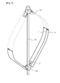
- FIG. 1 is a perspective view showing a Darrieus windmill according to an embodiment of the present invention
- FIG. 2 is a perspective view showing a Darrieus windmill according to another embodiment of the present invention.
- FIG. 3 is a view showing pressure distribution around a cross second of the blade used in FIG. 2 ;
- FIG. 4 is a view showing rotation of the secondary blade used in FIG. 2 ;
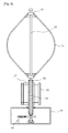
- FIG. 5 is a cross-sectional view showing a Darrieus windmill according to another embodiment of the present invention.
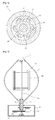
- FIG. 6 is a cross-sectional view showing the structure of a one-way clutch used in FIG. 5 ;
- FIG. 7 is a cross-sectional view showing a Darrieus windmill according to another embodiment of the present invention.
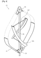
- FIGS. 8 and 9 are perspective views showing a Darrieus windmill according to another embodiment of the present invention.
- FIG. 1 is a perspective view showing a Darrieus windmill according to an embodiment of the present invention
- FIG. 2 is a perspective view showing a Darrieus windmill according to another embodiment of the present invention
- FIG. 3 is a view showing pressure distribution around a secondary blade used in FIG. 2
- FIG. 4 is a view showing rotation of the secondary blades used in FIG. 2
- FIG. 5 is a cross-sectional view showing a Darrieus windmill according to another embodiment of the present invention
- FIG. 6 is a cross-sectional view showing the structure of a one-way clutch used in FIG. 5
- FIG. 7 is a cross-sectional view showing a Darrieus windmill according to another embodiment of the present invention
- FIGS. 8 and 9 are perspective views showing a Darrieus windmill according to another embodiment of the present invention.
- the most important feature of the Darrieus windmill of the present invention is to have a starting means for self-starting at low wind speed.
- a Darrieus windmill having a starting means according to an embodiment of the present invention is described with reference to FIGS. 2 to 4 first.
- the present invention has a hybrid type windmill structure where a secondary windmill assisting the primary windmill is combined with a primary windmill, the Darrieus windmill.
- the primary windmill is a conventional Darrieus windmill.
- the shown primary windmill for example, is composed of a vertical primary shaft 35 and two primary blades 31 connected to the primary shaft 35.
- the upper and the lower end of the primary blade 31 are fixed to the fixing portions 39 disposed at the upper and lower end portions of the primary shaft 35.
- the number of primary blades 31 may be three, unlike those shown in the figures.
- the primary blades are arranged symmetrically about the primary shaft 35. Further, though not shown, the lower end of the primary shaft 35 is connected with a power generator.
- the primary blade 31 has a generally arc shape and a streamlined airfoil cross-section such that the primary shaft 35 is rotated by lift forces generated on the blade surfaces.
- the primary blade 31 used for the primary windmill can rotate with high number of revolution, because aerodynamics characteristics of the windmill are improved in a high wind speed range above a tip speed ratio (ratio of tangential speed of blade and natural wind speed, TSP) of one. Further, the primary shaft 35 is not affected by wind directions, because it is vertical.
- the primary blade 31 cannot start by itself below a tip speed ratio of 1, such that it cannot rotate the primary shaft. Therefore, the problem is that it is impossible to generate electricity in a low wind speed range.
- the secondary blades are provided as starting means for the primary shaft 35 in the present invention.
- the secondary blades generate rotating moment by means of drag at low wind speed and also generate rotating moment by means of lift at high wind speed.
- the secondary blades exert almost no load to the primary blades 31 rotating at high speed at high wind speed, by starting the primary shaft 35 by means of drag at low wind speed and rotating at high speed by means of lift at high wind speed, such that it is possible to use the advantages of the primary blades having excellent aerodynamics characteristics in a high wind speed range.
- a plurality of support arms 27 radially extending and perpendicular to the primary shaft 35 is formed on the outer circumference of the upper and lower portions of the primary shaft 35, and is in the rotational range of the primary blades 31. Further, the secondary blades 20 are attached to the ends of the four support arms 27, respectively, along a circumference having a predetermined radius in a plan perpendicular to the primary shaft 35.
- the secondary blade 20 is manufactured by press-forming a thin metal plate, such as an aluminum alloy, or extrusion-molding resin.
- the secondary blade 20 has a cross-section of a streamlined airfoil shape used for airplanes typically a 4-number series airfoil, an RAF airfoil, and a Geottingen airfoil, and it has a cut-off portion 25 formed on the lower surface B facing the primary shaft 35.
- the cut-off portion 25 is formed from the leading edge (a) to the trailing edge (b) at a position of 35% to 45% of the chord from the leading edge (a).
- the secondary blade 20 has an airfoil having a large lift coefficient at a low Reynolds number.
- Pressure distribution caused by the wind from the frontal area is formed around the secondary blade 20 as shown in FIG. 3 . That is, in the airfoil used for the secondary blade 20, pressure larger than the external atmospheric pressure is distributed at the front portion of the secondary blade 20, pressure substantially the same as the external atmospheric pressure is distributed at the rear portion, and negative pressure is distributed on the upper surface, because the flow speed is increased on the upper surface according to the shape of the air foil and accordingly the pressure is reduced. Therefore, the aerodynamics characteristics of the airfoil is affected little, even if the cut-off section 25 is formed at the rear portion of the lower surface of the secondary blade 20.
- lift is generated when the secondary blade 20 is attacked by wind from the frontal area (in the direction of an arrow C), such that the secondary blade 20 is rotated clockwise by the tangential component of the lift generated on the secondary blade 20.
- the moment generates rotation by being added to the tangential component of the lift generated on the secondary blade 20 attacked by the wind in the direction of an arrow C of FIG. 4 , and the secondary blade 20 is rotated by the lift generated on the secondary blade in a high wind speed range above a tip speed ratio of 1. That is, since the secondary blade 20 has the airfoil having a high lift coefficient at a low Reynolds number, the secondary blade 20 can be rotated at low wind speed below 1m/sec, such that it is possible to efficiently generate electricity. Further, since the secondary blade is made of a light material, such as an aluminum alloy, the entire weight of the secondary blade decreases and the load exerted on the secondary blades 20 by the centrifugal force is reduced.
- the embodiment uses the secondary blade type having a high lift coefficient at a low Reynolds number, the air resistance and lift force are generated in the secondary blade 20 and the secondary blade 20 is rotated by those forces. Therefore, it is possible to obtain rotating moment required to generate electricity from the secondary blade 20 even at any wind direction and speed. As a result, it is possible to rotate the secondary blade 20 in a wide wind speed range.
- the number of secondary blades 20 is not limited thereto, and three or less, five or more blades may be used and it is possible to achieve the same operation and effect as the embodiment described above even in those cases.
- the primary shaft 35 is rotated by starting the secondary blades at low wind speed. Further, when the wind speed increases and reaches a high wind speed range, the shaft can be rotated at high speed by the lift-typed primary blades 31. In this case, since the secondary blades 20 can be rotated at high speed by the lift, they give very little load to the first blades rotating at high speed in the high speed region, such that the efficiency of generating electricity is not much reduced.
- the secondary blades 20 are vertically disposed in the embodiment described above, the secondary blades 105 may be helically twisted about the primary shaft 35, as shown in FIG. 8 .
- the helical secondary blades 105 are fixed to the supports 107 horizontally attached to the outer circumference of the primary shaft 35.
- the aerodynamic characteristics are spirally exerted in the secondary blades 105, such that the secondary blades 105 can easily rotate against various wind directions and the starting performance of the primary shaft 35 can be improved.
- a secondary shaft 45 equipped with the secondary blades 20 is separately installed coaxially with the primary shaft.
- the secondary shaft 45 rotates with the primary shaft 35 at low wind speed, while it is detached from the primary shaft 35 and independently rotates from the primary shaft at a high wind speed.
- the primary shaft 35 having the lower portion connected with a power generator 93 is vertically disposed and lift-typed primary blades 31 are fixed to the primary shaft 35.
- the secondary shaft 45 surrounding the outer circumference of the primary shaft 35 which is positioned at the lower portion in the rotational region of the primary blades 31 is disposed coaxially with the primary shaft 35.
- the secondary shaft 45 is supported by a housing 91 which enables the secondary shaft 45 to rotate.
- the primary shaft 35 is inserted through the center of the secondary shaft 45, which is a hollow member, in which the inner circumference of the secondary shaft has a clearance from the outer circumference of the primary shaft.
- a one-way clutch 80 that can rotate in only one direction is disposed between the inner circumference of the secondary shaft 45 and the outer circumference of the primary shaft 35.
- An inner rotator 83 of the one-way clutch 80 is engaged with the primary shaft 35 and an outer rotator 81 is engaged with the secondary shaft 45.
- the primary and secondary shafts have different rotational speed at the high wind speed range, particularly, when the rotational speed of the primary shaft 35 is higher than that of the secondary shaft 45, the load of the primary shaft 35 for rotating the secondary shaft 45 is removed, such that the efficiency of generating electricity of the primary shaft 35 is not reduced.
- the secondary blades 20 are positioned within the rotational region of primary blades 31.
- a primary shaft 35 where the lower ends of the primary blades 31 are fixed is rotatably and vertically disposed in a housing 91.
- a secondary shaft 45 where the secondary blades 20 are fixed is coaxially disposed through the center of the primary shaft 35, which is a hollow member, and extends at a predetermined distance from both ends of the primary shaft 35.
- Power generators 95, 97 are connected to the lower portions of the primary shaft 35 and the secondary shaft 45, respectively, and the secondary blades 20 supported by support arms 27 are connected to the secondary shaft 45.
- a circular-plate shape rotary bracket 75 that can rotate individually from the secondary shaft 45 is disposed on the top of the secondary shaft 45, and the upper ends of the primary blades 31 are fixed to the rotary bracket 75 and the lower ends are fixed to the outer circumference of the primary shaft 35.
- a one-way clutch 70 is combined with the primary shaft 35 and the secondary shaft 45.
- the primary shaft is separated from the secondary shaft 45 and generates electricity while independently rotating. Further, since the individual power generator 97 is connected to the secondary shaft 45, the present invention can considerably improve the power generation capacity, because the primary shaft 35 and the secondary shaft 45 generate electricity independently.
- FIG. 1 shows a Darrieus windmill according to another embodiment of the present invention.
- the present invention is characterized by improvement of the conventional Darrieus blades to implement self-starting function in a low wind speed range.
- Both ends of the primary blades 5 are fixed to fixing portions 39 formed at the upper and lower portions of a vertical primary shaft 35.
- Other than two, three or four primary blades 5 may be disposed.
- the primary blade 5 has a cross-section of a streamlined airfoil and a cut-off portion 7 formed on the inner surface facing the primary shaft 35. Since the cut-off portion 7 has the same operation and effect as the secondary blades shown in FIG. 2 , the detailed description is omitted.
- secondary blades 20 with cut-off potions 7 attached to primary shaft 35 may be further included as starting means.
- the configuration of the secondary blade 20 is the same as that of the secondary blade shown in FIG. 2 .
- the windmill can start by itself by means of drag exerted on the blades in a low wind speed range.
Landscapes
- Engineering & Computer Science (AREA)
- Life Sciences & Earth Sciences (AREA)
- Sustainable Development (AREA)
- Sustainable Energy (AREA)
- Chemical & Material Sciences (AREA)
- Combustion & Propulsion (AREA)
- Mechanical Engineering (AREA)
- General Engineering & Computer Science (AREA)
- Physics & Mathematics (AREA)
- Fluid Mechanics (AREA)
- Wind Motors (AREA)
Applications Claiming Priority (2)
| Application Number | Priority Date | Filing Date | Title |
|---|---|---|---|
| KR1020080075358A KR100933790B1 (ko) | 2008-07-31 | 2008-07-31 | 수직축형 다리우스 풍차 |
| PCT/KR2009/004313 WO2010013981A2 (ko) | 2008-07-31 | 2009-07-31 | 수직축형 다리우스 풍차 |
Publications (2)
| Publication Number | Publication Date |
|---|---|
| EP2314867A2 true EP2314867A2 (de) | 2011-04-27 |
| EP2314867A4 EP2314867A4 (de) | 2014-03-05 |
Family
ID=41610874
Family Applications (1)
| Application Number | Title | Priority Date | Filing Date |
|---|---|---|---|
| EP09803186.7A Withdrawn EP2314867A4 (de) | 2008-07-31 | 2009-07-31 | Darrieus-windrad mit vertikaler welle |
Country Status (6)
| Country | Link |
|---|---|
| US (1) | US9284944B2 (de) |
| EP (1) | EP2314867A4 (de) |
| KR (1) | KR100933790B1 (de) |
| CN (1) | CN102099571A (de) |
| AU (1) | AU2009277220B2 (de) |
| WO (1) | WO2010013981A2 (de) |
Cited By (3)
| Publication number | Priority date | Publication date | Assignee | Title |
|---|---|---|---|---|
| AT12642U1 (de) * | 2011-08-17 | 2012-09-15 | Zsb Ag | Vorrichtung zur verwandlung einer fluidströmung in nutzbare antriebskraft |
| WO2013038215A1 (en) * | 2011-09-15 | 2013-03-21 | Macher Gépészeti És Elektronikai Kft. | Dual-turbine wind power station placed on a vertical axis |
| CN104160144A (zh) * | 2012-03-06 | 2014-11-19 | 艾克瑟斯能源集团有限公司 | 一种带有纵向和斜面螺纹刀片的交叉流涡轮机 |
Families Citing this family (35)
| Publication number | Priority date | Publication date | Assignee | Title |
|---|---|---|---|---|
| US20110049894A1 (en) * | 2006-10-06 | 2011-03-03 | Green William M | Electricity Generating Assembly |
| US20110027084A1 (en) * | 2009-07-31 | 2011-02-03 | Andrew Rekret | Novel turbine and blades |
| GR1007431B (el) * | 2010-01-08 | 2011-10-12 | Μυρων Ιωαννη Νουρης | Ανεμογεννητρια κατακορυφου αξονα με πτερυγια αναστολης υπερβολικης ταχυτητας |
| CH702753B1 (de) * | 2010-02-17 | 2013-11-29 | Zsb Ag | Doppelter Darrieus-Rotor. |
| CO6460078A1 (es) * | 2010-12-02 | 2012-06-15 | Ecopetrol Sa | Sistema para la generacion electrica a partir de energia eolica de baja velocidad con dos sistemas de ala impulsadora |
| EP2541048A3 (de) * | 2011-06-29 | 2014-06-25 | Fraunhofer-Gesellschaft zur Förderung der angewandten Forschung e.V. | Tragfläche, Windrotor und Windrotoranordnung |
| US9404474B2 (en) * | 2011-07-26 | 2016-08-02 | Wing Power Energy, Inc. | System and method for efficient wind power generation |
| RU2485345C1 (ru) * | 2012-02-02 | 2013-06-20 | Александр Владимирович Губанов | Турбина дарье модифицированная |
| KR101157389B1 (ko) * | 2012-02-03 | 2012-06-18 | 주식회사 한림메카트로닉스 | 저풍속 풍력발전장치 |
| CN103835889A (zh) * | 2012-11-23 | 2014-06-04 | 宁定光 | 一种风力发电机叶片 |
| JP5963146B2 (ja) * | 2013-05-25 | 2016-08-03 | 吉二 玉津 | 風切羽開閉翼システムを用いた垂直軸式水風車原動機 |
| CN103527401A (zh) * | 2013-10-15 | 2014-01-22 | 沈阳航空航天大学 | 垂直轴风力机使用开槽技术提高风能利用的方法 |
| US20150115607A1 (en) * | 2013-10-27 | 2015-04-30 | Lev Stepanov | Method of increasing of sensitivity and productivity of the wind generator with vertical axis at weak winds and device for his realization |
| CN103527403A (zh) * | 2013-11-08 | 2014-01-22 | 唐山海港中产新能源有限公司 | 一种垂直轴风轮 |
| CN104747375B (zh) * | 2013-12-30 | 2019-09-27 | 上海稳得新能源科技有限公司 | 改进的特大型垂直轴风力涡轮发电机系统 |
| CN104832372B (zh) * | 2014-02-12 | 2019-09-27 | 上海稳得新能源科技有限公司 | 10mw级空气动力制动的垂直轴风电系统 |
| CN103939297B (zh) * | 2014-05-06 | 2016-08-17 | 深圳邦忠风力发电科技股份有限公司 | 用于风电机组的风叶 |
| GB2527329B (en) | 2014-06-18 | 2018-09-12 | Abu Al Rubb Khalil | Turbine blade arrangement |
| CN104153944B (zh) * | 2014-08-06 | 2016-08-24 | 华北电力大学 | 一种大型海上垂直轴风力发电机组 |
| CN106032791A (zh) * | 2015-03-11 | 2016-10-19 | 安徽省伟德莱特新能源设备科技有限公司 | 一种升力互补型垂直轴风力发电机 |
| EP3311025A1 (de) * | 2015-06-18 | 2018-04-25 | New World Energy Enterprises Limited | Windturbine mit rotierendem augmentor |
| CN104976052B (zh) * | 2015-06-29 | 2018-04-06 | 东北农业大学 | 一种自适应式风力机 |
| EP4421323B1 (de) | 2015-10-30 | 2026-01-28 | Industrial Technologies and Services, LLC | Komplexe schraubenrotoren |
| CN105257469A (zh) * | 2015-11-23 | 2016-01-20 | 上海僖舜莱机电设备制造有限公司 | 混合动力型垂直轴风力发电机 |
| WO2019050408A1 (en) | 2017-09-08 | 2019-03-14 | Vervent B.V. | WIND TURBINE WITH VERTICAL AXIS |
| US10648452B1 (en) | 2019-01-23 | 2020-05-12 | Viktor Galstyan | Vertical axis wind turbine |
| IT202000009916A1 (it) * | 2020-05-05 | 2021-11-05 | He Powergreen S R L | Rotore per turbina idrodinamica |
| WO2021231106A1 (en) * | 2020-05-11 | 2021-11-18 | XFlow Energy Company | Separable fluid turbine rotor |
| AU2021324958A1 (en) * | 2020-08-10 | 2023-03-09 | Velocity Wind Turbines Llc | Configurable multi-purpose cross-flow wind turbine with performance enhancements |
| WO2022153338A1 (en) * | 2021-01-16 | 2022-07-21 | Maini Swati | Rotating airfoil for sustaining lift and method for generating lift |
| FR3119870B1 (fr) * | 2021-02-18 | 2024-04-19 | Collaborative Energy | Eolienne à flux transverse à pales jumelles, et à axes de rotation inclinés |
| JP7799987B2 (ja) * | 2021-03-15 | 2026-01-16 | 株式会社明電舎 | らせん型翼およびマイクロ水力発電装置。 |
| KR102845837B1 (ko) | 2023-06-01 | 2025-08-12 | 한국수력원자력 주식회사 | 다리우스형 수직축 풍력발전장치 |
| US12460615B2 (en) | 2024-02-23 | 2025-11-04 | Wattmakers LLC | Wind turbine with two sets of blades and aerogenerator |
| WO2025179174A1 (en) * | 2024-02-23 | 2025-08-28 | Wattmakers LLC | Wind turbine and aerogenerator |
Family Cites Families (31)
| Publication number | Priority date | Publication date | Assignee | Title |
|---|---|---|---|---|
| FR604390A (fr) * | 1925-10-09 | 1926-05-03 | Leblanc Vickers Maurice Sa | Turbine à axe de rotation transversal à la direction du courant |
| ES454192A1 (es) * | 1976-12-13 | 1977-12-01 | Zapata Martinez Valentin | Sistema para la obtencion y regulacion de energia a partir de corrientes aereas, maritimas o fluviales. |
| DE2829716A1 (de) * | 1977-07-07 | 1979-01-25 | Univ Gakko Hojin Tokai | Windkraftmaschine mit vertikaler achse |
| JPS5581280A (en) * | 1978-11-15 | 1980-06-19 | Agency Of Ind Science & Technol | Vertical shaft wind mill |
| US4449053A (en) * | 1981-07-27 | 1984-05-15 | Aluminum Company Of America | Vertical axis wind turbine |
| US4551631A (en) * | 1984-07-06 | 1985-11-05 | Trigilio Gaetano T | Wind and solar electric generating plant |
| DE3626917A1 (de) * | 1986-06-03 | 1987-12-10 | Erich Herter | Windturbine |
| GR910200234U (en) * | 1990-05-31 | 1992-07-30 | Mihail Valsamidis | Turbine wind machine with a vertical axis |
| US5463257A (en) * | 1993-11-23 | 1995-10-31 | Yea; Ton A. | Wind power machine |
| US5664418A (en) * | 1993-11-24 | 1997-09-09 | Walters; Victor | Whirl-wind vertical axis wind and water turbine |
| JPH09287549A (ja) * | 1996-04-23 | 1997-11-04 | Mitsubishi Heavy Ind Ltd | ハイブリッド形風力タービン |
| US6787934B2 (en) * | 2002-02-05 | 2004-09-07 | Pentti Henrik Parviainen | Turbine system |
| JP4037158B2 (ja) | 2002-04-25 | 2008-01-23 | 株式会社イーアンドイー | ダリウスロータ及びそれを用いた風力発電装置 |
| AU2003256960A1 (en) * | 2002-07-31 | 2004-02-16 | The Board Of Trustees Of The University Of Illinois | Wind turbine device |
| JP3451085B1 (ja) * | 2002-09-20 | 2003-09-29 | 常夫 野口 | 風力発電用の風車 |
| US7362004B2 (en) * | 2003-07-29 | 2008-04-22 | Becker William S | Wind turbine device |
| JPWO2005116446A1 (ja) * | 2004-05-27 | 2008-04-03 | 株式会社アイ・ピー・ビー | 垂直軸風車用ブレードおよび垂直軸風車 |
| JP2006161797A (ja) * | 2004-12-08 | 2006-06-22 | Takashuu:Kk | 風力発電装置 |
| JP4668673B2 (ja) * | 2005-04-25 | 2011-04-13 | 鳥海工業株式会社 | 風力回転装置 |
| US20070029807A1 (en) * | 2005-08-08 | 2007-02-08 | Clayton Kass | Methods and systems for generating wind energy |
| KR100774309B1 (ko) * | 2006-11-28 | 2007-11-08 | 한국해양연구원 | 헬리컬 터빈 발전시스템 |
| GB2448138B (en) * | 2007-04-02 | 2009-07-08 | Quiet Revolution Ltd | Improvements in or relating to wind turbines |
| US20090140528A1 (en) * | 2007-04-20 | 2009-06-04 | Bri Energy Solutions Limited | Wind and Updraft Turbine |
| HUP0700705A2 (en) * | 2007-10-30 | 2009-10-28 | Viktor Dr Gyoergyi | Vertical axis wind turbine and power station |
| US20090116968A1 (en) * | 2007-11-05 | 2009-05-07 | Mohle Robert E | Blade for wind turbines & an improved wind turbine |
| US8215897B2 (en) * | 2007-12-17 | 2012-07-10 | Douglass Karl J | Cylindrical wind turbine |
| CN100587259C (zh) * | 2008-01-18 | 2010-02-03 | 李益安 | 平板风车 |
| US20110037271A1 (en) * | 2008-04-21 | 2011-02-17 | Coriolis-Wind Inc | Wind turbine system and modular wind turbine unit therefor |
| US8096773B2 (en) * | 2009-03-11 | 2012-01-17 | Chin-Feng Chang | Vertical axis wind turbine |
| US8030792B2 (en) * | 2009-03-12 | 2011-10-04 | Eastern Wind Power | Vertical axis wind turbine system |
| ITCO20090026A1 (it) * | 2009-07-28 | 2011-01-28 | Windesign S R L | "turbina ibrida ad albero verticale per aerogeneratori di energia elettrica" |
-
2008
- 2008-07-31 KR KR1020080075358A patent/KR100933790B1/ko not_active Expired - Fee Related
-
2009
- 2009-07-31 US US12/989,956 patent/US9284944B2/en not_active Expired - Fee Related
- 2009-07-31 EP EP09803186.7A patent/EP2314867A4/de not_active Withdrawn
- 2009-07-31 WO PCT/KR2009/004313 patent/WO2010013981A2/ko not_active Ceased
- 2009-07-31 AU AU2009277220A patent/AU2009277220B2/en not_active Ceased
- 2009-07-31 CN CN2009801277589A patent/CN102099571A/zh active Pending
Cited By (5)
| Publication number | Priority date | Publication date | Assignee | Title |
|---|---|---|---|---|
| AT12642U1 (de) * | 2011-08-17 | 2012-09-15 | Zsb Ag | Vorrichtung zur verwandlung einer fluidströmung in nutzbare antriebskraft |
| WO2013038215A1 (en) * | 2011-09-15 | 2013-03-21 | Macher Gépészeti És Elektronikai Kft. | Dual-turbine wind power station placed on a vertical axis |
| CN104160144A (zh) * | 2012-03-06 | 2014-11-19 | 艾克瑟斯能源集团有限公司 | 一种带有纵向和斜面螺纹刀片的交叉流涡轮机 |
| EP2823181A4 (de) * | 2012-03-06 | 2015-06-24 | Axis Energy Group Pty Ltd | Querstromturbine mit vertikalen geraden und helikalen geneigten blättern |
| US10024168B2 (en) | 2012-03-06 | 2018-07-17 | Axis Energy Group Pty Ltd | Cross flow turbine with straight vertical and helical slanted blades |
Also Published As
| Publication number | Publication date |
|---|---|
| WO2010013981A3 (ko) | 2010-06-17 |
| KR100933790B1 (ko) | 2009-12-24 |
| AU2009277220A1 (en) | 2010-02-04 |
| EP2314867A4 (de) | 2014-03-05 |
| US20110042962A1 (en) | 2011-02-24 |
| AU2009277220B2 (en) | 2012-07-05 |
| US9284944B2 (en) | 2016-03-15 |
| WO2010013981A2 (ko) | 2010-02-04 |
| CN102099571A (zh) | 2011-06-15 |
Similar Documents
| Publication | Publication Date | Title |
|---|---|---|
| US9284944B2 (en) | Vertical shaft type darius windmill | |
| JP3451085B1 (ja) | 風力発電用の風車 | |
| US9989033B2 (en) | Horizontal axis wind or water turbine with forked or multi-blade upper segments | |
| EP1757806A1 (de) | Flügel für windrad mit vertikaler welle und windrad mit vertikaler welle | |
| JP5924125B2 (ja) | 垂直軸風車用ブレード及び垂直軸風車 | |
| EP2402592B1 (de) | Windenergieanlage | |
| WO2009072116A2 (en) | Turbine blade constructions particular useful in vertical-axis wind turbines | |
| KR100940013B1 (ko) | 저풍속 실속제어/정속운전용 풍력발전기 블레이드 | |
| CN102022259A (zh) | 升阻融合翼板型垂直轴风轮 | |
| KR20120139154A (ko) | 양력과 항력을 융합한 수직축 풍력발전기 | |
| KR20120061264A (ko) | 다중 종속 블레이드를 갖는 수직축형 터빈 | |
| JP4184847B2 (ja) | 風車装置及びそれを用いた風力発電装置 | |
| JP2005090332A (ja) | ダリウス形風車 | |
| CN103890381A (zh) | 组合全方向流动的涡轮机系统 | |
| JP2001065446A (ja) | 垂直軸型風車用翼列構造および垂直軸型風車 | |
| KR20090051669A (ko) | 풍력발전용 집풍형 풍차 | |
| KR101073096B1 (ko) | 수직축형 다리우스 풍차 | |
| JP2005171868A (ja) | 複合風車 | |
| CN220909892U (zh) | 立式风动机系统及立式风力发电系统 | |
| JP2012122477A (ja) | 抗力型風車および風力発電装置 | |
| GB2476830A (en) | Vertical axis wind powered generator | |
| KR101418674B1 (ko) | 루버유도형 풍력발전기 | |
| JP2011231759A (ja) | 揚力型垂直軸風車、揚力型垂直軸風車の翼、および揚力型垂直軸風車のローター | |
| CN221683103U (zh) | 一种空间流线叶尖半体长弦变桨风力发电叶片 | |
| GB2447913A (en) | Lift and drag driven wind turbine |
Legal Events
| Date | Code | Title | Description |
|---|---|---|---|
| PUAI | Public reference made under article 153(3) epc to a published international application that has entered the european phase |
Free format text: ORIGINAL CODE: 0009012 |
|
| 17P | Request for examination filed |
Effective date: 20101215 |
|
| AK | Designated contracting states |
Kind code of ref document: A2 Designated state(s): AT BE BG CH CY CZ DE DK EE ES FI FR GB GR HR HU IE IS IT LI LT LU LV MC MK MT NL NO PL PT RO SE SI SK SM TR |
|
| AX | Request for extension of the european patent |
Extension state: AL BA RS |
|
| DAX | Request for extension of the european patent (deleted) | ||
| A4 | Supplementary search report drawn up and despatched |
Effective date: 20140204 |
|
| RIC1 | Information provided on ipc code assigned before grant |
Ipc: F03D 3/06 20060101AFI20140129BHEP |
|
| STAA | Information on the status of an ep patent application or granted ep patent |
Free format text: STATUS: THE APPLICATION IS DEEMED TO BE WITHDRAWN |
|
| 18D | Application deemed to be withdrawn |
Effective date: 20140201 |