EP2314901A2 - Ebauche de boîtier de soupape et ensemble de soupape - Google Patents
Ebauche de boîtier de soupape et ensemble de soupape Download PDFInfo
- Publication number
- EP2314901A2 EP2314901A2 EP20100013868 EP10013868A EP2314901A2 EP 2314901 A2 EP2314901 A2 EP 2314901A2 EP 20100013868 EP20100013868 EP 20100013868 EP 10013868 A EP10013868 A EP 10013868A EP 2314901 A2 EP2314901 A2 EP 2314901A2
- Authority
- EP
- European Patent Office
- Prior art keywords
- feed channels
- longitudinal axis
- ventilgehäuserohling
- receiving space
- feed
- Prior art date
- Legal status (The legal status is an assumption and is not a legal conclusion. Google has not performed a legal analysis and makes no representation as to the accuracy of the status listed.)
- Granted
Links
Images

Classifications
-
- F—MECHANICAL ENGINEERING; LIGHTING; HEATING; WEAPONS; BLASTING
- F16—ENGINEERING ELEMENTS AND UNITS; GENERAL MEASURES FOR PRODUCING AND MAINTAINING EFFECTIVE FUNCTIONING OF MACHINES OR INSTALLATIONS; THERMAL INSULATION IN GENERAL
- F16K—VALVES; TAPS; COCKS; ACTUATING-FLOATS; DEVICES FOR VENTING OR AERATING
- F16K27/00—Construction of housing; Use of materials therefor
- F16K27/003—Housing formed from a plurality of the same valve elements
-
- F—MECHANICAL ENGINEERING; LIGHTING; HEATING; WEAPONS; BLASTING
- F16—ENGINEERING ELEMENTS AND UNITS; GENERAL MEASURES FOR PRODUCING AND MAINTAINING EFFECTIVE FUNCTIONING OF MACHINES OR INSTALLATIONS; THERMAL INSULATION IN GENERAL
- F16K—VALVES; TAPS; COCKS; ACTUATING-FLOATS; DEVICES FOR VENTING OR AERATING
- F16K27/00—Construction of housing; Use of materials therefor
- F16K27/02—Construction of housing; Use of materials therefor of lift valves
- F16K27/0263—Construction of housing; Use of materials therefor of lift valves multiple way valves
-
- Y—GENERAL TAGGING OF NEW TECHNOLOGICAL DEVELOPMENTS; GENERAL TAGGING OF CROSS-SECTIONAL TECHNOLOGIES SPANNING OVER SEVERAL SECTIONS OF THE IPC; TECHNICAL SUBJECTS COVERED BY FORMER USPC CROSS-REFERENCE ART COLLECTIONS [XRACs] AND DIGESTS
- Y10—TECHNICAL SUBJECTS COVERED BY FORMER USPC
- Y10T—TECHNICAL SUBJECTS COVERED BY FORMER US CLASSIFICATION
- Y10T137/00—Fluid handling
- Y10T137/1624—Destructible or deformable element controlled
- Y10T137/1632—Destructible element
-
- Y—GENERAL TAGGING OF NEW TECHNOLOGICAL DEVELOPMENTS; GENERAL TAGGING OF CROSS-SECTIONAL TECHNOLOGIES SPANNING OVER SEVERAL SECTIONS OF THE IPC; TECHNICAL SUBJECTS COVERED BY FORMER USPC CROSS-REFERENCE ART COLLECTIONS [XRACs] AND DIGESTS
- Y10—TECHNICAL SUBJECTS COVERED BY FORMER USPC
- Y10T—TECHNICAL SUBJECTS COVERED BY FORMER US CLASSIFICATION
- Y10T137/00—Fluid handling
- Y10T137/5109—Convertible
-
- Y—GENERAL TAGGING OF NEW TECHNOLOGICAL DEVELOPMENTS; GENERAL TAGGING OF CROSS-SECTIONAL TECHNOLOGIES SPANNING OVER SEVERAL SECTIONS OF THE IPC; TECHNICAL SUBJECTS COVERED BY FORMER USPC CROSS-REFERENCE ART COLLECTIONS [XRACs] AND DIGESTS
- Y10—TECHNICAL SUBJECTS COVERED BY FORMER USPC
- Y10T—TECHNICAL SUBJECTS COVERED BY FORMER US CLASSIFICATION
- Y10T137/00—Fluid handling
- Y10T137/598—With repair, tapping, assembly, or disassembly means
- Y10T137/6007—Assembling or disassembling multi way valve
-
- Y—GENERAL TAGGING OF NEW TECHNOLOGICAL DEVELOPMENTS; GENERAL TAGGING OF CROSS-SECTIONAL TECHNOLOGIES SPANNING OVER SEVERAL SECTIONS OF THE IPC; TECHNICAL SUBJECTS COVERED BY FORMER USPC CROSS-REFERENCE ART COLLECTIONS [XRACs] AND DIGESTS
- Y10—TECHNICAL SUBJECTS COVERED BY FORMER USPC
- Y10T—TECHNICAL SUBJECTS COVERED BY FORMER US CLASSIFICATION
- Y10T137/00—Fluid handling
- Y10T137/8593—Systems
- Y10T137/87249—Multiple inlet with multiple outlet
Definitions
- the invention relates to a Ventilge Reifenohling and a valve assembly from the invention Ventilge Reifenohlingen.
- Ventilge Reifenohling is already known, which is produced inexpensively as a casting and high flexibility in assembling a valve assembly allows, as it can be reworked with very little effort and then assembled into a variety of valve kits.
- this VentilgeNeillohling two parallel receiving spaces for two valve inserts with a total of ten incoming or outgoing lines are coupled, which are closed in the initial state mainly by thin partition walls to the receiving space.
- various intermediate walls are removed.
- the valve housing blank according to the invention has a receiving space for a valve insert, which has a longitudinal axis, wherein at least two opposite to the longitudinal axis first pair of feed channels from the outside of the blank laterally, in particular radially, to the receiving space extend, wherein the pairs of feed channels in the direction of the longitudinal axis considered offset from each other and wherein only one of the feed channels to the receiving space is open and the other feed channels are closed by a destructible partition to the receiving space.
- a plurality of feed channels to the receiving space is provided in the housing blank according to the invention.
- the valve housing blank may in particular be designed as a precision casting, for example as a stainless steel investment casting.
- the two first pairs of feed channels should lie in a common plane with respect to their axes.
- this plane is also perpendicular to the longitudinal axis of the receiving space. It is therefore preferable to feed four channels to the receiving space, namely four feed channels, which lie in a plane.
- supply channels is to emphasize that this term is not limited to the subsequent use of the channels as an inlet, but of course should also include channels that serve as fluid drainage channels in later use.
- a further embodiment of the invention provides that a plurality of axially superimposed double pairs of feed channels, which lie opposite one another with respect to the longitudinal axis and extend laterally from the outside of the blank, in particular radially, to the receiving space.
- the other pairs of double feed channels are offset in the direction of the longitudinal axis to each other. Only one of the feed channels per double pair is open to the receiving space, whereas the other feed channels are closed by a destructible partition to the receiving space.
- double pair is to be understood in the following two pairs of feed channels, each pair with respect to the longitudinal axis has opposite feed channels and the two pairs in the longitudinal direction seen offset from each other.
- the aforementioned first pairs also form a double pair.
- the other pairs of feed channels should be in a common plane with respect to their respective axes.
- this plane may preferably extend perpendicular to the longitudinal axis, so that each double pair forms a plane so to speak and the planes axially spaced from each other (axially with respect to the longitudinal axis) and parallel to each other.
- the feed channels of the various planes in the direction of the longitudinal axis should lie in groups one behind the other, that is not to be circumferentially offset from each other. That is, the orientation of the feed channels in the circumferential direction is the same at the supply channels of the different levels. This increases the variability of the Ventilge Reifenohlinge.
- the Ventilge Reifenohling is a pure casting, in particular metal or plastic injection molded part, but also a sintered part would be possible.
- the feed channels are designed as tubular extensions.
- the Ventilge Reifenohling is not a block-like part, but a filigree, easy-to-build part, which is composed, so to speak, only of thin channel walls.
- ribs which connect axially superimposed projections together and preferably merge integrally into the extensions.
- These ribs can run radially to the longitudinal axis.
- Recesses, preferably in the form of holes, in the ribs represent fastening recesses over which a plurality of housing blanks can be clamped or screwed together.
- the associated pairs of feed channels are intended to be perpendicular to one another. This means that the already aligned axes of the two each forming a pair, opposite feed channels intersect the axes of the other pair at 90 ° and, in addition, in the longitudinal axis.
- valve housing blank according to the invention is not designed as a block, but as a filigree part with thin channel walls, there would be the danger that they can not be stably clamped together when fitting and securing several valve housings.
- laterally outwardly projecting spacers are formed on the blanks side of the feed channels.
- spacers should preferably extend to the radially outer ends of the feed channels. This means that the spacers together with the feed channels act as a support surface when several valve housings are placed against one another.
- each spacer can extend into the two planes of planar end faces of adjacent feed channels (ie in the circumferential direction of directly adjacent feed channels) and terminate there to form a contact surface. This means that such a spacer acts in two directions, so to speak, since it has two contact surfaces, which are aligned differently.
- the end faces of the feed channels and / or the contact surfaces should, viewed in the longitudinal direction, lie on the sides of a square, so that the valve housing blank has an envelope in the form of a square in the longitudinal direction. This facilitates the composition of several valve housings to a valve assembly.
- the spacers are in particular designed as radial ribs.
- the rib thickness is preferably not greater than the thickness of the channel walls forming the supply channels, so that no accumulation of material takes place and injection molding or casting is not impeded by increased material accumulations.
- first pairs of feed channels and / or the at least other double pair have their own spacers, which preferably each lie in the plane of the double pair spanned by the axes of the associated feed channels.
- the at least one open feed channel can end at its outer end with a cross-sectional widening, so that under certain circumstances a seal, in particular of graphite or the like, can be used.
- the receiving space ends according to an embodiment of an end wall, which is a destructible partition, on the opposite side of an axial feed channel ends.
- an axial feed channel ends according to an embodiment of an end wall, which is a destructible partition, on the opposite side of an axial feed channel ends.
- the receiving space may terminate outwardly in a flat flange surface, and also on the opposite side of the blank there may be a flange surface parallel thereto.
- the flange surfaces, the end faces and the contact surfaces lie on / in the surfaces of a cube or cuboid, in particular a cuboid with a square base.
- the intermediate wall directly adjoins the receiving space.
- a valve seat is cast in at least one channel, which is not reworked.
- the invention also relates to a valve assembly having a plurality of contiguous valve housings of valve blanks according to the invention, wherein a plurality of intermediate walls are at least partially removed to form continuous channels and to bring a plurality of feed channels in fluid communication with each other.
- the individual valve housings can of course also have obliquely inwardly extending receiving spaces or feed channels extending at an angle to one another, for example, six or eight feed channels could also run into the receiving space in one plane.
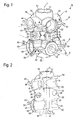
- FIG. 1 a Ventilge Reifenohling 10 is shown, which is integrally molded from plastic or metal, in particular aluminum or stainless steel, especially by investment casting.
- the Ventilge Reifenohling 10, as shown, is not post-machined.
- the blank 10 has one, also in FIG. 2 easily recognizable receiving space 12, which has several heels with increasing depth and is getting narrower from the cross section.
- the receiving space 12 has a longitudinal axis L.
- feed channels 14 which are formed by thin walls which have a tubular shape.
- An upper double pair of feed channels 14 to 20 and an axially offset thereto arranged lower double pair of feed channels 22 to 28 extend in the embodiment shown with their axes A all to the longitudinal axis L.
- the upper double pair of feed channels 14 to 20, also called first pairs of feed channels 14 to 20, has a first pair with respect to the longitudinal axis of diametrically opposite feed channels 14, 16 and a second pair, also with respect to the longitudinal axis of diametrically opposed feed channels 18, 20.
- the axes A of both pairs are perpendicular to the longitudinal axis L and span a plane which is also perpendicular to the longitudinal axis L.
- the lower double pair has feed channels 22 to 28, which are aligned as well as those of the upper double pair, that is, extend as far radially outward, seen in the direction of the longitudinal axis L below the corresponding feed channels 14 to 20 are, that is without angular offset to These are arranged and also with their axes A span a plane which is perpendicular to the longitudinal axis L and thus parallel to the upper level.
- Pro double pair of feed channels is, as in FIG. 2 can be seen, only one feed channel 16 and 22 to the receiving space 12 towards open. All other supply channels are separated by a thin intermediate wall 30, which preferably directly adjoins the receiving space 12.
- valve seat 33 When pouring the valve housing blank 10 at the same time at least at a feed channel (here at the channel 12) a valve seat 33 is cast with.
- the valve seat 33 is an annular shoulder, which is designed in particular with an axially outwardly extending bead. The bead should improve the tightness.
- the valve seat 33 is not reworked.
- radially extending integrally molded ribs 36 are provided which connect the tubular walls formed as axially superimposed walls of the feed channels 14 to 28 together.
- the ribs 36 have a wall thickness which corresponds at most to the thickness of the wall of the feed channels 14 to 28.
- the ribs 36 extend as in FIG. 1 is clearly visible in two mutually perpendicular planes and in planes which are defined by exactly axially superimposed axes A.
- the ribs 36 have fastening recesses 38 in the form of holes. These holes are already excluded, in particular during casting, that is, that no machining is required for their production.
- spacers 40 are integrally formed on the valve housing blank 10.
- spacers 40 are in the preferred embodiment, but are not intended to be limiting, thin ribs having a wall thickness thinner than the walls of the feed channels 14 to 28.
- the spacers 40 are preferably arranged lying in the plane of a double pair of feed channels 14 to 20 or 22 to 28.
- the spacers 40 project laterally outwardly with respect to the longitudinal axis L and, according to the illustrated preferred embodiment, extend to the radially outer ends of the feed channels 14 to 28, that is, to the corresponding tube wall, as will be explained in more detail below.
- the tube walls of the feed channels 14 to 28 each end in particular in a planar end face 42 to 48. These end faces 42 to 48 form a pair of axially superimposed feed channels 14 to 28 a total of four levels, E1 to E4 (see Fig. 3 ) which form pairwise parallel planes, the planes E1, E2 of one pair being perpendicular to the planes E3, E4 of the other.
- the spacers 40 extend up to these, defined by the end faces 40 to 48 levels E1 to E4, preferably each spacer 40 extends into two perpendicular planes E1 to E4 and is executed, so to speak as a corner rib.
- the spacers 40 have plane contact surfaces 50, 52, which terminate in the aforementioned, defined by the end faces 42 to 48 levels E1 to E4.
- each pair of double feed channels 14 to 20 and 22 to 28 each have their own spacers 40, for the illustrated embodiment four spacers 40, which also serve as connecting ribs between adjacent walls of feed channels 14 to 28.
- VentilgeNeillohlinge can be provided, which in the axial direction, based on FIG. 1 , so to speak, are halved and have only a double pair of feed channels.
- FIG. 2 can also be seen that the two feed channels 16, 22 in the two superimposed planes, which are open from the house to the receiving space 12, viewed in the longitudinal direction on diagonally opposite sides of the longitudinal axis L and, so to speak, only axially offset from one another.
- These feed channels 16, 22 terminate radially outwardly with a cross-sectional enlargement 60, which has already been formed during spraying, and which is stepped.
- this extension 60 for example, a seal or a connecting pipe can be accommodated.
- FIG. 3 shows that a plurality of valve housing, which from the Ventilge Reifenohlingen 10 after the Figures 1 and 2 are made, very simple and modular to any valve assembly (also called valve block) are composable.
- the connection is preferably via clamping elements, in particular threaded rods 70 which extend through the recesses 38 in the ribs 36 and fasten adjacent valve housing together.
- valve inserts 80 which project into receiving spaces 12 and the supply channels 14 to 28 opposite each other after actuation flow-connect with each other or separate to allow different flow patterns.
- the valve bodies 81 can be pressed against a valve seat to close a channel.
- valve housing 80 for receiving a valve insert 80, but that there are valve housings which merely serve as a conduit.
- a receiving space 12 may be closed by a plug in the region of its free end, if necessary.
- any valve assembly can be put together, which can also be arbitrarily complex.
- the basic structure remains the same. This means that you can assemble extremely complex valve kits with a kind of Ventilge Reifenohlingen and also has to apply very little machining.
- each feed channel 14 to 28 has an individual shape or inscription, here in the form of numbers 90.
- other valve inserts 80 can of course be installed in the valve housing, for example, check valves, filters or chokes.
Landscapes
- Engineering & Computer Science (AREA)
- General Engineering & Computer Science (AREA)
- Mechanical Engineering (AREA)
- Valve Housings (AREA)
- Check Valves (AREA)
- Sliding Valves (AREA)
- Braking Systems And Boosters (AREA)
Applications Claiming Priority (1)
| Application Number | Priority Date | Filing Date | Title |
|---|---|---|---|
| DE200920014234 DE202009014234U1 (de) | 2009-10-21 | 2009-10-21 | Ventilgehäuserohling sowie Ventilbausatz |
Publications (3)
| Publication Number | Publication Date |
|---|---|
| EP2314901A2 true EP2314901A2 (fr) | 2011-04-27 |
| EP2314901A3 EP2314901A3 (fr) | 2013-11-20 |
| EP2314901B1 EP2314901B1 (fr) | 2017-06-28 |
Family
ID=41429222
Family Applications (1)
| Application Number | Title | Priority Date | Filing Date |
|---|---|---|---|
| EP10013868.4A Active EP2314901B1 (fr) | 2009-10-21 | 2010-10-21 | Ebauche de boîtier de soupape et ensemble de soupape |
Country Status (4)
| Country | Link |
|---|---|
| US (1) | US8505576B2 (fr) |
| EP (1) | EP2314901B1 (fr) |
| CN (1) | CN102042433B (fr) |
| DE (1) | DE202009014234U1 (fr) |
Families Citing this family (10)
| Publication number | Priority date | Publication date | Assignee | Title |
|---|---|---|---|---|
| US10533485B2 (en) * | 2014-01-13 | 2020-01-14 | Coldfire, Inc. | Control valve |
| DE112016003576T5 (de) * | 2015-08-06 | 2018-05-03 | Dana Heavy Vehicle Systems Group, Llc | Steuer- und zuführungsventilandordnung für ein reifendruck-managementsystem |
| WO2017024216A1 (fr) * | 2015-08-06 | 2017-02-09 | Dana Heavy Vehicle Systems Group, Llc | Ensemble valve pour un système de gestion de la pression des pneus |
| US10214059B2 (en) | 2015-10-16 | 2019-02-26 | Dana Heavy Vehicle Systems Group, Llc | Tire pressure management system and method of decreasing tire pressure |
| ITUB20161092A1 (it) * | 2016-02-26 | 2017-08-26 | Bonomi Ind S R L | Valvola a sfera e metodo di fabbricazione |
| BE1024953B1 (fr) * | 2017-01-31 | 2018-08-30 | Out And Out Chemistry Sprl | Méthode pour connecter au moins deux vannes fluidiques et le système de communication fluidique mis en œuvre |
| CN206723534U (zh) * | 2017-05-04 | 2017-12-08 | 浙江三花汽车零部件有限公司 | 调温阀 |
| USD923753S1 (en) * | 2019-11-01 | 2021-06-29 | TSI Products, Inc. | Valve housing |
| CN114087400B (zh) * | 2021-12-10 | 2025-04-25 | 日丰企业(佛山)有限公司 | 一种分水器 |
| US20240052613A1 (en) * | 2022-08-09 | 2024-02-15 | Kohler Co. | Electromechanical shower valve |
Citations (1)
| Publication number | Priority date | Publication date | Assignee | Title |
|---|---|---|---|---|
| DE202008004672U1 (de) | 2008-04-04 | 2008-07-17 | Bürkert Werke GmbH & Co. KG | Ventilgehäuserohling, Ventilbausatz sowie Ventilgruppe |
Family Cites Families (10)
| Publication number | Priority date | Publication date | Assignee | Title |
|---|---|---|---|---|
| US2399515A (en) * | 1943-10-01 | 1946-04-30 | Thompson Prod Inc | Multiple quick disconnect coupling |
| US3572369A (en) * | 1969-02-07 | 1971-03-23 | William C Kaufman | Removable seat engaging element |
| US3572368A (en) * | 1969-09-02 | 1971-03-23 | Honeywell Inc | Pneumatic control system manifold means |
| DE3422336A1 (de) | 1984-06-15 | 1985-12-19 | Abig Werke Carry Gross GmbH & Co KG, 7770 Überlingen | Ventilgehaeuse fuer den anschluss eines heizkoerpers |
| DE4214009C1 (de) | 1992-04-29 | 1993-10-21 | Kaiser Gmbh & Co Kg | Elektrische Unterputz-Abzweigdose, insbesondere für den Installationsbus |
| US5441079A (en) * | 1994-04-22 | 1995-08-15 | Tri-Clover, Inc. | Manifold valve assemblies |
| WO1996036829A1 (fr) * | 1995-05-19 | 1996-11-21 | Bürkert Werke GmbH & Co. | Structure modulaire de soupape |
| CA2182259C (fr) * | 1996-07-29 | 2002-01-29 | Silvano Breda | Valve a levier unique et cartouche avec chambre de melange incorporee et canalisation separee |
| US6240941B1 (en) * | 1998-07-23 | 2001-06-05 | Laars, Inc. | Modular, interconnectable valve |
| CA2742081A1 (fr) * | 2008-10-31 | 2010-05-06 | Jacob Telepciak | Bloc collecteur pour systemes d'osmose inverse |
-
2009
- 2009-10-21 DE DE200920014234 patent/DE202009014234U1/de not_active Expired - Lifetime
-
2010
- 2010-10-20 US US12/908,236 patent/US8505576B2/en active Active
- 2010-10-21 CN CN201010526269.5A patent/CN102042433B/zh active Active
- 2010-10-21 EP EP10013868.4A patent/EP2314901B1/fr active Active
Patent Citations (1)
| Publication number | Priority date | Publication date | Assignee | Title |
|---|---|---|---|---|
| DE202008004672U1 (de) | 2008-04-04 | 2008-07-17 | Bürkert Werke GmbH & Co. KG | Ventilgehäuserohling, Ventilbausatz sowie Ventilgruppe |
Also Published As
| Publication number | Publication date |
|---|---|
| EP2314901B1 (fr) | 2017-06-28 |
| CN102042433A (zh) | 2011-05-04 |
| US8505576B2 (en) | 2013-08-13 |
| DE202009014234U1 (de) | 2009-12-24 |
| US20110089361A1 (en) | 2011-04-21 |
| EP2314901A3 (fr) | 2013-11-20 |
| CN102042433B (zh) | 2015-06-03 |
Similar Documents
| Publication | Publication Date | Title |
|---|---|---|
| EP2314901B1 (fr) | Ebauche de boîtier de soupape et ensemble de soupape | |
| DE2357671C2 (de) | Durchflußbegrenzungsventil | |
| DE102015121351A1 (de) | Mischereinsatz, statischer Mischer sowie Herstellverfahren | |
| DE102021111839A1 (de) | Vorrichtung zur Handhabung von Fluid eines zumindest teilweise elektrisch angetriebenen Fahrzeugs | |
| EP2107284B1 (fr) | Ebauche de boîtier de soupape, kit de soupape et groupe de soupape | |
| EP2530365A1 (fr) | Garniture de soupape pour une armature sanitaire | |
| DE1134659B (de) | Kopfstueck an einem Filtergehaeuse | |
| EP2639364B1 (fr) | Corps de base pour une robinetterie sanitaire | |
| EP3982028A1 (fr) | Module de distribution, en particulier pour une unité de séparation d'un agencement de dispositif de processus modulaire | |
| DE102018221689B4 (de) | Hydraulikventilsystem mit einem Ventilgehäuse | |
| EP1321698B1 (fr) | Dipositif pour connecter plusieurs composants hydrauliques ou pneumatiques, en particulier soupapes électromagnétiques | |
| DE69715111T2 (de) | Durchflussregelventil | |
| DE68910431T2 (de) | Fluidsteuerventil. | |
| EP1614944B1 (fr) | Vanne à voies multiples ou vanne de distribution | |
| DE20211696U1 (de) | Modulares Filtergehäuse | |
| EP0103564B1 (fr) | Boîtier pour un robinet à piston | |
| DE102014009831A1 (de) | Mehrteiliger, konzentrischer Verteiler und Verfahren zur Herstellung des Verteilers | |
| EP1761722B1 (fr) | Soupape de commutation | |
| DE3038460A1 (de) | Kombinierter vorlaufverteiler und ruecklaufsammler, insbesondere fuer warmwasser-fussbodenheizung | |
| EP2746631A1 (fr) | Élément de garniture de soupape | |
| DE2308191A1 (de) | Druckmittelverteiler | |
| DE4020754A1 (de) | Waermetauscher fuer zwei fluessige medien | |
| EP1088581A2 (fr) | Dispositif de filtration avec au moins deux chambres de filtration | |
| DE102012001968A1 (de) | Fluiddurchströmbare Baugruppe | |
| DE19748345C2 (de) | Schieberventil |
Legal Events
| Date | Code | Title | Description |
|---|---|---|---|
| PUAI | Public reference made under article 153(3) epc to a published international application that has entered the european phase |
Free format text: ORIGINAL CODE: 0009012 |
|
| AK | Designated contracting states |
Kind code of ref document: A2 Designated state(s): AL AT BE BG CH CY CZ DE DK EE ES FI FR GB GR HR HU IE IS IT LI LT LU LV MC MK MT NL NO PL PT RO RS SE SI SK SM TR |
|
| AX | Request for extension of the european patent |
Extension state: BA ME |
|
| RAP1 | Party data changed (applicant data changed or rights of an application transferred) |
Owner name: BUERKERT WERKE GMBH |
|
| PUAL | Search report despatched |
Free format text: ORIGINAL CODE: 0009013 |
|
| AK | Designated contracting states |
Kind code of ref document: A3 Designated state(s): AL AT BE BG CH CY CZ DE DK EE ES FI FR GB GR HR HU IE IS IT LI LT LU LV MC MK MT NL NO PL PT RO RS SE SI SK SM TR |
|
| AX | Request for extension of the european patent |
Extension state: BA ME |
|
| RIC1 | Information provided on ipc code assigned before grant |
Ipc: F16K 27/00 20060101AFI20131016BHEP Ipc: F16K 27/02 20060101ALI20131016BHEP |
|
| 17P | Request for examination filed |
Effective date: 20140509 |
|
| RBV | Designated contracting states (corrected) |
Designated state(s): AL AT BE BG CH CY CZ DE DK EE ES FI FR GB GR HR HU IE IS IT LI LT LU LV MC MK MT NL NO PL PT RO RS SE SI SK SM TR |
|
| GRAP | Despatch of communication of intention to grant a patent |
Free format text: ORIGINAL CODE: EPIDOSNIGR1 |
|
| STAA | Information on the status of an ep patent application or granted ep patent |
Free format text: STATUS: GRANT OF PATENT IS INTENDED |
|
| INTG | Intention to grant announced |
Effective date: 20170130 |
|
| GRAS | Grant fee paid |
Free format text: ORIGINAL CODE: EPIDOSNIGR3 |
|
| GRAA | (expected) grant |
Free format text: ORIGINAL CODE: 0009210 |
|
| STAA | Information on the status of an ep patent application or granted ep patent |
Free format text: STATUS: THE PATENT HAS BEEN GRANTED |
|
| AK | Designated contracting states |
Kind code of ref document: B1 Designated state(s): AL AT BE BG CH CY CZ DE DK EE ES FI FR GB GR HR HU IE IS IT LI LT LU LV MC MK MT NL NO PL PT RO RS SE SI SK SM TR |
|
| REG | Reference to a national code |
Ref country code: GB Ref legal event code: FG4D Free format text: NOT ENGLISH |
|
| REG | Reference to a national code |
Ref country code: CH Ref legal event code: EP |
|
| REG | Reference to a national code |
Ref country code: AT Ref legal event code: REF Ref document number: 905168 Country of ref document: AT Kind code of ref document: T Effective date: 20170715 |
|
| REG | Reference to a national code |
Ref country code: IE Ref legal event code: FG4D Free format text: LANGUAGE OF EP DOCUMENT: GERMAN |
|
| REG | Reference to a national code |
Ref country code: DE Ref legal event code: R096 Ref document number: 502010013800 Country of ref document: DE |
|
| PG25 | Lapsed in a contracting state [announced via postgrant information from national office to epo] |
Ref country code: GR Free format text: LAPSE BECAUSE OF FAILURE TO SUBMIT A TRANSLATION OF THE DESCRIPTION OR TO PAY THE FEE WITHIN THE PRESCRIBED TIME-LIMIT Effective date: 20170929 Ref country code: HR Free format text: LAPSE BECAUSE OF FAILURE TO SUBMIT A TRANSLATION OF THE DESCRIPTION OR TO PAY THE FEE WITHIN THE PRESCRIBED TIME-LIMIT Effective date: 20170628 Ref country code: FI Free format text: LAPSE BECAUSE OF FAILURE TO SUBMIT A TRANSLATION OF THE DESCRIPTION OR TO PAY THE FEE WITHIN THE PRESCRIBED TIME-LIMIT Effective date: 20170628 Ref country code: LT Free format text: LAPSE BECAUSE OF FAILURE TO SUBMIT A TRANSLATION OF THE DESCRIPTION OR TO PAY THE FEE WITHIN THE PRESCRIBED TIME-LIMIT Effective date: 20170628 Ref country code: NO Free format text: LAPSE BECAUSE OF FAILURE TO SUBMIT A TRANSLATION OF THE DESCRIPTION OR TO PAY THE FEE WITHIN THE PRESCRIBED TIME-LIMIT Effective date: 20170928 |
|
| REG | Reference to a national code |
Ref country code: NL Ref legal event code: MP Effective date: 20170628 |
|
| REG | Reference to a national code |
Ref country code: LT Ref legal event code: MG4D |
|
| PG25 | Lapsed in a contracting state [announced via postgrant information from national office to epo] |
Ref country code: LV Free format text: LAPSE BECAUSE OF FAILURE TO SUBMIT A TRANSLATION OF THE DESCRIPTION OR TO PAY THE FEE WITHIN THE PRESCRIBED TIME-LIMIT Effective date: 20170628 Ref country code: RS Free format text: LAPSE BECAUSE OF FAILURE TO SUBMIT A TRANSLATION OF THE DESCRIPTION OR TO PAY THE FEE WITHIN THE PRESCRIBED TIME-LIMIT Effective date: 20170628 Ref country code: SE Free format text: LAPSE BECAUSE OF FAILURE TO SUBMIT A TRANSLATION OF THE DESCRIPTION OR TO PAY THE FEE WITHIN THE PRESCRIBED TIME-LIMIT Effective date: 20170628 Ref country code: NL Free format text: LAPSE BECAUSE OF FAILURE TO SUBMIT A TRANSLATION OF THE DESCRIPTION OR TO PAY THE FEE WITHIN THE PRESCRIBED TIME-LIMIT Effective date: 20170628 Ref country code: BG Free format text: LAPSE BECAUSE OF FAILURE TO SUBMIT A TRANSLATION OF THE DESCRIPTION OR TO PAY THE FEE WITHIN THE PRESCRIBED TIME-LIMIT Effective date: 20170928 |
|
| PG25 | Lapsed in a contracting state [announced via postgrant information from national office to epo] |
Ref country code: SK Free format text: LAPSE BECAUSE OF FAILURE TO SUBMIT A TRANSLATION OF THE DESCRIPTION OR TO PAY THE FEE WITHIN THE PRESCRIBED TIME-LIMIT Effective date: 20170628 Ref country code: EE Free format text: LAPSE BECAUSE OF FAILURE TO SUBMIT A TRANSLATION OF THE DESCRIPTION OR TO PAY THE FEE WITHIN THE PRESCRIBED TIME-LIMIT Effective date: 20170628 Ref country code: RO Free format text: LAPSE BECAUSE OF FAILURE TO SUBMIT A TRANSLATION OF THE DESCRIPTION OR TO PAY THE FEE WITHIN THE PRESCRIBED TIME-LIMIT Effective date: 20170628 Ref country code: CZ Free format text: LAPSE BECAUSE OF FAILURE TO SUBMIT A TRANSLATION OF THE DESCRIPTION OR TO PAY THE FEE WITHIN THE PRESCRIBED TIME-LIMIT Effective date: 20170628 |
|
| PG25 | Lapsed in a contracting state [announced via postgrant information from national office to epo] |
Ref country code: IT Free format text: LAPSE BECAUSE OF FAILURE TO SUBMIT A TRANSLATION OF THE DESCRIPTION OR TO PAY THE FEE WITHIN THE PRESCRIBED TIME-LIMIT Effective date: 20170628 Ref country code: IS Free format text: LAPSE BECAUSE OF FAILURE TO SUBMIT A TRANSLATION OF THE DESCRIPTION OR TO PAY THE FEE WITHIN THE PRESCRIBED TIME-LIMIT Effective date: 20171028 Ref country code: SM Free format text: LAPSE BECAUSE OF FAILURE TO SUBMIT A TRANSLATION OF THE DESCRIPTION OR TO PAY THE FEE WITHIN THE PRESCRIBED TIME-LIMIT Effective date: 20170628 Ref country code: PL Free format text: LAPSE BECAUSE OF FAILURE TO SUBMIT A TRANSLATION OF THE DESCRIPTION OR TO PAY THE FEE WITHIN THE PRESCRIBED TIME-LIMIT Effective date: 20170628 Ref country code: ES Free format text: LAPSE BECAUSE OF FAILURE TO SUBMIT A TRANSLATION OF THE DESCRIPTION OR TO PAY THE FEE WITHIN THE PRESCRIBED TIME-LIMIT Effective date: 20170628 |
|
| REG | Reference to a national code |
Ref country code: DE Ref legal event code: R097 Ref document number: 502010013800 Country of ref document: DE |
|
| PG25 | Lapsed in a contracting state [announced via postgrant information from national office to epo] |
Ref country code: DK Free format text: LAPSE BECAUSE OF FAILURE TO SUBMIT A TRANSLATION OF THE DESCRIPTION OR TO PAY THE FEE WITHIN THE PRESCRIBED TIME-LIMIT Effective date: 20170628 |
|
| PLBE | No opposition filed within time limit |
Free format text: ORIGINAL CODE: 0009261 |
|
| STAA | Information on the status of an ep patent application or granted ep patent |
Free format text: STATUS: NO OPPOSITION FILED WITHIN TIME LIMIT |
|
| PG25 | Lapsed in a contracting state [announced via postgrant information from national office to epo] |
Ref country code: MC Free format text: LAPSE BECAUSE OF FAILURE TO SUBMIT A TRANSLATION OF THE DESCRIPTION OR TO PAY THE FEE WITHIN THE PRESCRIBED TIME-LIMIT Effective date: 20170628 |
|
| REG | Reference to a national code |
Ref country code: CH Ref legal event code: PL |
|
| 26N | No opposition filed |
Effective date: 20180329 |
|
| GBPC | Gb: european patent ceased through non-payment of renewal fee |
Effective date: 20171021 |
|
| REG | Reference to a national code |
Ref country code: IE Ref legal event code: MM4A |
|
| REG | Reference to a national code |
Ref country code: FR Ref legal event code: ST Effective date: 20180629 |
|
| PG25 | Lapsed in a contracting state [announced via postgrant information from national office to epo] |
Ref country code: LU Free format text: LAPSE BECAUSE OF NON-PAYMENT OF DUE FEES Effective date: 20171021 Ref country code: LI Free format text: LAPSE BECAUSE OF NON-PAYMENT OF DUE FEES Effective date: 20171031 Ref country code: CH Free format text: LAPSE BECAUSE OF NON-PAYMENT OF DUE FEES Effective date: 20171031 Ref country code: GB Free format text: LAPSE BECAUSE OF NON-PAYMENT OF DUE FEES Effective date: 20171021 |
|
| REG | Reference to a national code |
Ref country code: BE Ref legal event code: MM Effective date: 20171031 |
|
| PG25 | Lapsed in a contracting state [announced via postgrant information from national office to epo] |
Ref country code: FR Free format text: LAPSE BECAUSE OF NON-PAYMENT OF DUE FEES Effective date: 20171031 Ref country code: BE Free format text: LAPSE BECAUSE OF NON-PAYMENT OF DUE FEES Effective date: 20171031 Ref country code: SI Free format text: LAPSE BECAUSE OF FAILURE TO SUBMIT A TRANSLATION OF THE DESCRIPTION OR TO PAY THE FEE WITHIN THE PRESCRIBED TIME-LIMIT Effective date: 20170628 |
|
| PG25 | Lapsed in a contracting state [announced via postgrant information from national office to epo] |
Ref country code: MT Free format text: LAPSE BECAUSE OF FAILURE TO SUBMIT A TRANSLATION OF THE DESCRIPTION OR TO PAY THE FEE WITHIN THE PRESCRIBED TIME-LIMIT Effective date: 20170628 |
|
| PG25 | Lapsed in a contracting state [announced via postgrant information from national office to epo] |
Ref country code: IE Free format text: LAPSE BECAUSE OF NON-PAYMENT OF DUE FEES Effective date: 20171021 |
|
| REG | Reference to a national code |
Ref country code: AT Ref legal event code: MM01 Ref document number: 905168 Country of ref document: AT Kind code of ref document: T Effective date: 20171021 |
|
| PG25 | Lapsed in a contracting state [announced via postgrant information from national office to epo] |
Ref country code: AT Free format text: LAPSE BECAUSE OF NON-PAYMENT OF DUE FEES Effective date: 20171021 |
|
| PG25 | Lapsed in a contracting state [announced via postgrant information from national office to epo] |
Ref country code: HU Free format text: LAPSE BECAUSE OF FAILURE TO SUBMIT A TRANSLATION OF THE DESCRIPTION OR TO PAY THE FEE WITHIN THE PRESCRIBED TIME-LIMIT; INVALID AB INITIO Effective date: 20101021 |
|
| PG25 | Lapsed in a contracting state [announced via postgrant information from national office to epo] |
Ref country code: CY Free format text: LAPSE BECAUSE OF NON-PAYMENT OF DUE FEES Effective date: 20170628 |
|
| PG25 | Lapsed in a contracting state [announced via postgrant information from national office to epo] |
Ref country code: MK Free format text: LAPSE BECAUSE OF FAILURE TO SUBMIT A TRANSLATION OF THE DESCRIPTION OR TO PAY THE FEE WITHIN THE PRESCRIBED TIME-LIMIT Effective date: 20170628 |
|
| PG25 | Lapsed in a contracting state [announced via postgrant information from national office to epo] |
Ref country code: TR Free format text: LAPSE BECAUSE OF FAILURE TO SUBMIT A TRANSLATION OF THE DESCRIPTION OR TO PAY THE FEE WITHIN THE PRESCRIBED TIME-LIMIT Effective date: 20170628 |
|
| PG25 | Lapsed in a contracting state [announced via postgrant information from national office to epo] |
Ref country code: PT Free format text: LAPSE BECAUSE OF FAILURE TO SUBMIT A TRANSLATION OF THE DESCRIPTION OR TO PAY THE FEE WITHIN THE PRESCRIBED TIME-LIMIT Effective date: 20170628 |
|
| PG25 | Lapsed in a contracting state [announced via postgrant information from national office to epo] |
Ref country code: AL Free format text: LAPSE BECAUSE OF FAILURE TO SUBMIT A TRANSLATION OF THE DESCRIPTION OR TO PAY THE FEE WITHIN THE PRESCRIBED TIME-LIMIT Effective date: 20170628 |
|
| P01 | Opt-out of the competence of the unified patent court (upc) registered |
Effective date: 20230523 |
|
| PGFP | Annual fee paid to national office [announced via postgrant information from national office to epo] |
Ref country code: DE Payment date: 20251024 Year of fee payment: 16 |