EP2314907A1 - Dispositif d'éclairage - Google Patents
Dispositif d'éclairage Download PDFInfo
- Publication number
- EP2314907A1 EP2314907A1 EP10013759A EP10013759A EP2314907A1 EP 2314907 A1 EP2314907 A1 EP 2314907A1 EP 10013759 A EP10013759 A EP 10013759A EP 10013759 A EP10013759 A EP 10013759A EP 2314907 A1 EP2314907 A1 EP 2314907A1
- Authority
- EP
- European Patent Office
- Prior art keywords
- diffuser body
- diaphragm
- diffuser
- lighting lamp
- leds
- Prior art date
- Legal status (The legal status is an assumption and is not a legal conclusion. Google has not performed a legal analysis and makes no representation as to the accuracy of the status listed.)
- Withdrawn
Links
- 238000005286 illumination Methods 0.000 title 1
- 238000012216 screening Methods 0.000 claims abstract description 5
- 229920002994 synthetic fiber Polymers 0.000 claims description 5
- 239000004744 fabric Substances 0.000 claims description 3
- 238000005192 partition Methods 0.000 claims 3
- 229920000515 polycarbonate Polymers 0.000 claims 2
- 239000004417 polycarbonate Substances 0.000 claims 2
- 238000004519 manufacturing process Methods 0.000 description 4
- 229910052736 halogen Inorganic materials 0.000 description 3
- 150000002367 halogens Chemical class 0.000 description 3
- 241000238631 Hexapoda Species 0.000 description 2
- 239000000428 dust Substances 0.000 description 2
- 230000000694 effects Effects 0.000 description 2
- 230000004907 flux Effects 0.000 description 2
- 239000002184 metal Substances 0.000 description 2
- 230000035515 penetration Effects 0.000 description 2
- 229910000831 Steel Inorganic materials 0.000 description 1
- 238000004140 cleaning Methods 0.000 description 1
- 239000003086 colorant Substances 0.000 description 1
- 238000005520 cutting process Methods 0.000 description 1
- 230000001419 dependent effect Effects 0.000 description 1
- 238000011161 development Methods 0.000 description 1
- 230000018109 developmental process Effects 0.000 description 1
- 238000009792 diffusion process Methods 0.000 description 1
- 238000003780 insertion Methods 0.000 description 1
- 230000037431 insertion Effects 0.000 description 1
- 238000003698 laser cutting Methods 0.000 description 1
- 229910001234 light alloy Inorganic materials 0.000 description 1
- 239000000463 material Substances 0.000 description 1
- 238000012986 modification Methods 0.000 description 1
- 230000004048 modification Effects 0.000 description 1
- 239000010959 steel Substances 0.000 description 1
- 239000012780 transparent material Substances 0.000 description 1
Images
Classifications
-
- F—MECHANICAL ENGINEERING; LIGHTING; HEATING; WEAPONS; BLASTING
- F21—LIGHTING
- F21V—FUNCTIONAL FEATURES OR DETAILS OF LIGHTING DEVICES OR SYSTEMS THEREOF; STRUCTURAL COMBINATIONS OF LIGHTING DEVICES WITH OTHER ARTICLES, NOT OTHERWISE PROVIDED FOR
- F21V11/00—Screens not covered by groups F21V1/00, F21V3/00, F21V7/00 or F21V9/00
- F21V11/08—Screens not covered by groups F21V1/00, F21V3/00, F21V7/00 or F21V9/00 using diaphragms containing one or more apertures
- F21V11/12—Screens not covered by groups F21V1/00, F21V3/00, F21V7/00 or F21V9/00 using diaphragms containing one or more apertures of slot type
-
- F—MECHANICAL ENGINEERING; LIGHTING; HEATING; WEAPONS; BLASTING
- F21—LIGHTING
- F21S—NON-PORTABLE LIGHTING DEVICES; SYSTEMS THEREOF; VEHICLE LIGHTING DEVICES SPECIALLY ADAPTED FOR VEHICLE EXTERIORS
- F21S4/00—Lighting devices or systems using a string or strip of light sources
- F21S4/20—Lighting devices or systems using a string or strip of light sources with light sources held by or within elongate supports
-
- F—MECHANICAL ENGINEERING; LIGHTING; HEATING; WEAPONS; BLASTING
- F21—LIGHTING
- F21Y—INDEXING SCHEME ASSOCIATED WITH SUBCLASSES F21K, F21L, F21S and F21V, RELATING TO THE FORM OR THE KIND OF THE LIGHT SOURCES OR OF THE COLOUR OF THE LIGHT EMITTED
- F21Y2103/00—Elongate light sources, e.g. fluorescent tubes
- F21Y2103/10—Elongate light sources, e.g. fluorescent tubes comprising a linear array of point-like light-generating elements
-
- F—MECHANICAL ENGINEERING; LIGHTING; HEATING; WEAPONS; BLASTING
- F21—LIGHTING
- F21Y—INDEXING SCHEME ASSOCIATED WITH SUBCLASSES F21K, F21L, F21S and F21V, RELATING TO THE FORM OR THE KIND OF THE LIGHT SOURCES OR OF THE COLOUR OF THE LIGHT EMITTED
- F21Y2115/00—Light-generating elements of semiconductor light sources
- F21Y2115/10—Light-emitting diodes [LED]
Definitions
- the present invention refers to a lighting lamp according to the preamble of claim 1.
- lamps are known in various embodiments. Besides the tubular lighting lamps, lamps with incandescence or halogen bulbs have the common characteristic of comprising a diffuser body, lighting means housed in said diffuser body, hanging means or a supporting base, as well as the required circuital components.
- the diffuser body may be provided transparent, or opaque, for example bell-shaped, delimiting the outgoing light beam, wherein the lamp is freely visible.
- Such lamps may have hanging means, for example in form of a chain or tube which can be hooked to a hook fixed onto the ceiling or, for example in case of floor lamps or desk lamps they may have a base, wherein interposed between said base and diffuser body are supporting elements, for example in form of a tube, for example curved (in case of floor lamps or desk lamps) or several rods or tubes articulated to each other like arms, with springs or counterweights interposed, for the desired positioning of the diffuser body (for example in the case of desk lamps).
- hanging means for example in form of a chain or tube which can be hooked to a hook fixed onto the ceiling or, for example in case of floor lamps or desk lamps they may have a base, wherein interposed between said base and diffuser body are supporting elements, for example in form of a tube, for example curved (in case of floor lamps or desk lamps) or several rods or tubes articulated to each other like arms, with springs or counterweights interposed, for the desired positioning of the diffuser body (for example in the case of desk lamps
- a variation of the intensity of the luminous flux may occur, with halogen lamps, generally with two different voltages, for example of 25 and 50 W, using a transformer, generally housed in the base.
- the intensity of the light flux may also be varied through a converter or trimmer.
- lamps, headlights and downlights with lighting means in form of incandescence, halogen, fluorescent and low consumption lamps reveal practical limits.
- lamps with a light dimmer practically absorb the same amount of power regardless of the set variation.
- a variation of the position of the emitted light beam requires an articulated support for the diffuser body and, as a consequence, higher reproduction costs with respect to a fixed diffuser body.
- the diffuser body generally has only one large opening for the outgoing of the light. Furthermore, providing for a plurality of exposed lamps arranged spaced on a strip-like support - such solution being definitely suitable for industrial lighting, shops, shop-windows and the like, but less suitable for household lighting where less strong and preferably more diffused lighting is required - for the diffusion of light along a relevant length is also known.
- the production of the openings for the outgoing of the light may be provided in a simple, controlled and quick manner through laser beam cutting.
- the lamps may be assembled in a simple, automatable and quick manner given that the lamp is made up of a limited number of components.
- advantageously used as lighting means are LEDs, which currently have good lighting performance, occupy little space and are easily available, for example, on a tape-like support, for example a fabric, which in turn can be easily fixed on a stiff strip-like support, for example made of metal or synthetic material, which can be easily inserted or fixed in the tubular diffuser body.
- Said stiff support may divide, for example diametrically, the tubular body into two chambers, in which the LEDs are arranged towards the chamber with the openings for the outgoing of the light.
- LEDs emitting light of respectively different colours.
- the use of LEDs also allows eliminating the prior art transformers and allows power supply by means of conventional AC adapters which can be inserted directly into the power supply sockets.
- the diffuser body may be fixed directly to a base, in which intermediate supports - for floor lamps - and articulated arms, springs and so and so forth - for desk lamps - may be eliminated.
- the provided screening diaphragm protects the diffuser body against penetration of dust, insects and dirt and facilitates the cleaning of the diffuser body. It may also be tubular, for example made of synthetic and transparent material, with a longitudinal slot which allows, when closed, an easy insertion thereof into the diffuser body and, when released, a self-locking positioning thereof into the diffuser body. This also facilitates the assembly of the lamp.
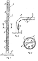
- the lighting lamp according to the invention is indicated in its entirety with 1 and, according to a first aspect of the proposed disclosure, it has a tubular diffuser body 2 which does not require any supporting element but it can be directly fixed to a base 3, shaped at will.
- the opening for the outgoing of the light is not provided for solely at the opening 4 of the diffuser body opposite to the base 3, such opening 4 possibly being provided for closable by a cover element, for example removable, not illustrated, but it may be divided into a plurality of openings 5, shaped at will, for example rectangular, circular, and so on and so forth, which are distributed along the diffuser body 2 at will.
- said openings 5 are provided for on and along half of the surface of the diffuser body 2, which may have a circular or polygonal cross section at will. This allows obtaining a stabilised light emission at will, depending on the desired lighting results and effects.
- the openings 5 are easily obtainable through laser cutting in the diffuser body 2, preferably made of metal, for example steel, light alloy and so on and so forth.
- LEDs - monochrome or coloured at which are provided for in a number suitable for the geometric dimensions of the diffuser body 2 and the light to be emitted - are preferably provided for as lighting means 6.
- Said LEDs 6 may, for example, be fixed to a flexible tape-like support 7, for example consisting of a fabric, in turn fixed to a stiff strip-like supporting element 8 inserted into the diffuser body 2, for example as a diametral diaphragm and forming two internal chambers 9 and 10, as illustrated in figure 2 , the chamber 10 in the illustrated example representing a blind chamber.
- the LEDs 6 are arranged in the chamber 9, in whose semi-surface of the diffuser body 2 the openings 5 are provided.
- Said diaphragm 11 may be made of stiff transparent synthetic material, for straight diffusers, figure 1 , or flexible synthetic material, for curved diffusers, figure 3 .
- the LEDs 6 may be divided - in terms of circuit - into two or more groups, inserted through known connection means, like switches or the like, not illustrated, supported in the base 3, or controllable by a remote control, also not illustrated.
Landscapes
- Engineering & Computer Science (AREA)
- General Engineering & Computer Science (AREA)
- Circuit Arrangements For Discharge Lamps (AREA)
- Non-Portable Lighting Devices Or Systems Thereof (AREA)
Applications Claiming Priority (1)
| Application Number | Priority Date | Filing Date | Title |
|---|---|---|---|
| IT000041A ITCO20090041A1 (it) | 2009-10-20 | 2009-10-20 | "lampada di illuminazione" |
Publications (1)
| Publication Number | Publication Date |
|---|---|
| EP2314907A1 true EP2314907A1 (fr) | 2011-04-27 |
Family
ID=42320783
Family Applications (1)
| Application Number | Title | Priority Date | Filing Date |
|---|---|---|---|
| EP10013759A Withdrawn EP2314907A1 (fr) | 2009-10-20 | 2010-10-19 | Dispositif d'éclairage |
Country Status (2)
| Country | Link |
|---|---|
| EP (1) | EP2314907A1 (fr) |
| IT (1) | ITCO20090041A1 (fr) |
Cited By (2)
| Publication number | Priority date | Publication date | Assignee | Title |
|---|---|---|---|---|
| ITPD20110267A1 (it) * | 2011-08-10 | 2013-02-11 | Massimo Crivello | Dispositivo di illuminazione |
| IT201700029945A1 (it) * | 2017-03-17 | 2018-09-17 | Biosyntex S R L | Tubo diffusore |
Citations (6)
| Publication number | Priority date | Publication date | Assignee | Title |
|---|---|---|---|---|
| US3548186A (en) * | 1968-01-24 | 1970-12-15 | Walter B Brock | Reading lamp shield |
| US4575786A (en) * | 1982-04-13 | 1986-03-11 | British Aerospace Public Limited Company | Radiation emitting apparatus |
| DE3826161A1 (de) * | 1988-08-01 | 1990-02-08 | Stiers Unterhaltungselektronik | Lichtfaechergeraet |
| WO2000031463A1 (fr) * | 1998-11-24 | 2000-06-02 | Lumileds Lighting U.S., L.L.C. | Logement et systeme de montage pour dispositif eclairant en bande |
| DE20319640U1 (de) * | 2003-12-02 | 2004-03-18 | Ho, Sung Tao | LED-Lampenröhre |
| US20050036322A1 (en) * | 2003-07-28 | 2005-02-17 | Veffer Samuel C. | Lamp |
-
2009
- 2009-10-20 IT IT000041A patent/ITCO20090041A1/it unknown
-
2010
- 2010-10-19 EP EP10013759A patent/EP2314907A1/fr not_active Withdrawn
Patent Citations (6)
| Publication number | Priority date | Publication date | Assignee | Title |
|---|---|---|---|---|
| US3548186A (en) * | 1968-01-24 | 1970-12-15 | Walter B Brock | Reading lamp shield |
| US4575786A (en) * | 1982-04-13 | 1986-03-11 | British Aerospace Public Limited Company | Radiation emitting apparatus |
| DE3826161A1 (de) * | 1988-08-01 | 1990-02-08 | Stiers Unterhaltungselektronik | Lichtfaechergeraet |
| WO2000031463A1 (fr) * | 1998-11-24 | 2000-06-02 | Lumileds Lighting U.S., L.L.C. | Logement et systeme de montage pour dispositif eclairant en bande |
| US20050036322A1 (en) * | 2003-07-28 | 2005-02-17 | Veffer Samuel C. | Lamp |
| DE20319640U1 (de) * | 2003-12-02 | 2004-03-18 | Ho, Sung Tao | LED-Lampenröhre |
Cited By (3)
| Publication number | Priority date | Publication date | Assignee | Title |
|---|---|---|---|---|
| ITPD20110267A1 (it) * | 2011-08-10 | 2013-02-11 | Massimo Crivello | Dispositivo di illuminazione |
| IT201700029945A1 (it) * | 2017-03-17 | 2018-09-17 | Biosyntex S R L | Tubo diffusore |
| WO2018167721A1 (fr) * | 2017-03-17 | 2018-09-20 | BIOSYNTEX S.r.l. | Tube diffuseur |
Also Published As
| Publication number | Publication date |
|---|---|
| ITCO20090041A1 (it) | 2011-04-20 |
Similar Documents
| Publication | Publication Date | Title |
|---|---|---|
| US9970609B2 (en) | Arrangements of decorative elements, lighting fixtures, and methods for providing illumination | |
| US6402345B1 (en) | Louver assembly with translucent louver baffles | |
| US20060098444A1 (en) | Lighting system | |
| JP3161425U (ja) | シーリングライト | |
| WO2010126083A1 (fr) | Dispositif d'éclairage | |
| US20140268816A1 (en) | Lighting fixtures and methods for providing illumination | |
| EP2314907A1 (fr) | Dispositif d'éclairage | |
| US20040257802A1 (en) | Support rod for a light source | |
| KR200444363Y1 (ko) | 조명등용 장식구 | |
| KR20120124233A (ko) | 기둥형 led 등기구 | |
| US7798683B2 (en) | Torchiere floor lamp having hidden light | |
| KR200385055Y1 (ko) | 엘이디에 의한 보조발광부를 갖는 조명등 | |
| US2264141A (en) | Lighting fixture | |
| US20020145872A1 (en) | Decorative lighting frame | |
| KR200413753Y1 (ko) | 천정등 | |
| KR200411570Y1 (ko) | 조명등용 전등커버 | |
| CN214745134U (zh) | 一种伸缩台灯 | |
| US20080049427A1 (en) | Multicolored lighting fixture | |
| KR200475682Y1 (ko) | 광효율 개선형 매입형 조명기구 | |
| GB2438636A (en) | Ceiling tile with integrated LED | |
| JP6590376B2 (ja) | 照明装置及びこの照明装置を備えた梁あらわし天井 | |
| KR101778000B1 (ko) | 칵테일 잔 형태로 된 장식 조명등 | |
| JP2025179353A (ja) | セードを備える照明器具 | |
| JP2010251083A (ja) | Led照明灯の管構造 | |
| KR200362105Y1 (ko) | 천정등의 투광장식재 조립구조 |
Legal Events
| Date | Code | Title | Description |
|---|---|---|---|
| PUAI | Public reference made under article 153(3) epc to a published international application that has entered the european phase |
Free format text: ORIGINAL CODE: 0009012 |
|
| AK | Designated contracting states |
Kind code of ref document: A1 Designated state(s): AL AT BE BG CH CY CZ DE DK EE ES FI FR GB GR HR HU IE IS IT LI LT LU LV MC MK MT NL NO PL PT RO RS SE SI SK SM TR |
|
| AX | Request for extension of the european patent |
Extension state: BA ME |
|
| STAA | Information on the status of an ep patent application or granted ep patent |
Free format text: STATUS: THE APPLICATION IS DEEMED TO BE WITHDRAWN |
|
| 18D | Application deemed to be withdrawn |
Effective date: 20111028 |