EP2314908A2 - Unité émettrice de lumière stationnaire - Google Patents
Unité émettrice de lumière stationnaire Download PDFInfo
- Publication number
- EP2314908A2 EP2314908A2 EP10013847A EP10013847A EP2314908A2 EP 2314908 A2 EP2314908 A2 EP 2314908A2 EP 10013847 A EP10013847 A EP 10013847A EP 10013847 A EP10013847 A EP 10013847A EP 2314908 A2 EP2314908 A2 EP 2314908A2
- Authority
- EP
- European Patent Office
- Prior art keywords
- light
- reflector
- emitting unit
- devices
- emitting
- Prior art date
- Legal status (The legal status is an assumption and is not a legal conclusion. Google has not performed a legal analysis and makes no representation as to the accuracy of the status listed.)
- Withdrawn
Links
Images


Classifications
-
- F—MECHANICAL ENGINEERING; LIGHTING; HEATING; WEAPONS; BLASTING
- F21—LIGHTING
- F21S—NON-PORTABLE LIGHTING DEVICES; SYSTEMS THEREOF; VEHICLE LIGHTING DEVICES SPECIALLY ADAPTED FOR VEHICLE EXTERIORS
- F21S8/00—Lighting devices intended for fixed installation
- F21S8/03—Lighting devices intended for fixed installation of surface-mounted type
- F21S8/033—Lighting devices intended for fixed installation of surface-mounted type the surface being a wall or like vertical structure, e.g. building facade
-
- F—MECHANICAL ENGINEERING; LIGHTING; HEATING; WEAPONS; BLASTING
- F21—LIGHTING
- F21V—FUNCTIONAL FEATURES OR DETAILS OF LIGHTING DEVICES OR SYSTEMS THEREOF; STRUCTURAL COMBINATIONS OF LIGHTING DEVICES WITH OTHER ARTICLES, NOT OTHERWISE PROVIDED FOR
- F21V7/00—Reflectors for light sources
- F21V7/0083—Array of reflectors for a cluster of light sources, e.g. arrangement of multiple light sources in one plane
-
- F—MECHANICAL ENGINEERING; LIGHTING; HEATING; WEAPONS; BLASTING
- F21—LIGHTING
- F21V—FUNCTIONAL FEATURES OR DETAILS OF LIGHTING DEVICES OR SYSTEMS THEREOF; STRUCTURAL COMBINATIONS OF LIGHTING DEVICES WITH OTHER ARTICLES, NOT OTHERWISE PROVIDED FOR
- F21V7/00—Reflectors for light sources
- F21V7/22—Reflectors for light sources characterised by materials, surface treatments or coatings, e.g. dichroic reflectors
- F21V7/24—Reflectors for light sources characterised by materials, surface treatments or coatings, e.g. dichroic reflectors characterised by the material
-
- F—MECHANICAL ENGINEERING; LIGHTING; HEATING; WEAPONS; BLASTING
- F21—LIGHTING
- F21V—FUNCTIONAL FEATURES OR DETAILS OF LIGHTING DEVICES OR SYSTEMS THEREOF; STRUCTURAL COMBINATIONS OF LIGHTING DEVICES WITH OTHER ARTICLES, NOT OTHERWISE PROVIDED FOR
- F21V7/00—Reflectors for light sources
- F21V7/22—Reflectors for light sources characterised by materials, surface treatments or coatings, e.g. dichroic reflectors
- F21V7/28—Reflectors for light sources characterised by materials, surface treatments or coatings, e.g. dichroic reflectors characterised by coatings
-
- F—MECHANICAL ENGINEERING; LIGHTING; HEATING; WEAPONS; BLASTING
- F21—LIGHTING
- F21S—NON-PORTABLE LIGHTING DEVICES; SYSTEMS THEREOF; VEHICLE LIGHTING DEVICES SPECIALLY ADAPTED FOR VEHICLE EXTERIORS
- F21S8/00—Lighting devices intended for fixed installation
- F21S8/04—Lighting devices intended for fixed installation intended only for mounting on a ceiling or the like overhead structures
-
- F—MECHANICAL ENGINEERING; LIGHTING; HEATING; WEAPONS; BLASTING
- F21—LIGHTING
- F21V—FUNCTIONAL FEATURES OR DETAILS OF LIGHTING DEVICES OR SYSTEMS THEREOF; STRUCTURAL COMBINATIONS OF LIGHTING DEVICES WITH OTHER ARTICLES, NOT OTHERWISE PROVIDED FOR
- F21V17/00—Fastening of component parts of lighting devices, e.g. shades, globes, refractors, reflectors, filters, screens, grids or protective cages
- F21V17/10—Fastening of component parts of lighting devices, e.g. shades, globes, refractors, reflectors, filters, screens, grids or protective cages characterised by specific fastening means or way of fastening
- F21V17/16—Fastening of component parts of lighting devices, e.g. shades, globes, refractors, reflectors, filters, screens, grids or protective cages characterised by specific fastening means or way of fastening by deformation of parts; Snap action mounting
- F21V17/164—Fastening of component parts of lighting devices, e.g. shades, globes, refractors, reflectors, filters, screens, grids or protective cages characterised by specific fastening means or way of fastening by deformation of parts; Snap action mounting the parts being subjected to bending, e.g. snap joints
-
- F—MECHANICAL ENGINEERING; LIGHTING; HEATING; WEAPONS; BLASTING
- F21—LIGHTING
- F21V—FUNCTIONAL FEATURES OR DETAILS OF LIGHTING DEVICES OR SYSTEMS THEREOF; STRUCTURAL COMBINATIONS OF LIGHTING DEVICES WITH OTHER ARTICLES, NOT OTHERWISE PROVIDED FOR
- F21V21/00—Supporting, suspending, or attaching arrangements for lighting devices; Hand grips
- F21V21/14—Adjustable mountings
- F21V21/30—Pivoted housings or frames
-
- F—MECHANICAL ENGINEERING; LIGHTING; HEATING; WEAPONS; BLASTING
- F21—LIGHTING
- F21V—FUNCTIONAL FEATURES OR DETAILS OF LIGHTING DEVICES OR SYSTEMS THEREOF; STRUCTURAL COMBINATIONS OF LIGHTING DEVICES WITH OTHER ARTICLES, NOT OTHERWISE PROVIDED FOR
- F21V29/00—Protecting lighting devices from thermal damage; Cooling or heating arrangements specially adapted for lighting devices or systems
- F21V29/50—Cooling arrangements
- F21V29/70—Cooling arrangements characterised by passive heat-dissipating elements, e.g. heat-sinks
-
- F—MECHANICAL ENGINEERING; LIGHTING; HEATING; WEAPONS; BLASTING
- F21—LIGHTING
- F21V—FUNCTIONAL FEATURES OR DETAILS OF LIGHTING DEVICES OR SYSTEMS THEREOF; STRUCTURAL COMBINATIONS OF LIGHTING DEVICES WITH OTHER ARTICLES, NOT OTHERWISE PROVIDED FOR
- F21V29/00—Protecting lighting devices from thermal damage; Cooling or heating arrangements specially adapted for lighting devices or systems
- F21V29/85—Protecting lighting devices from thermal damage; Cooling or heating arrangements specially adapted for lighting devices or systems characterised by the material
- F21V29/89—Metals
-
- F—MECHANICAL ENGINEERING; LIGHTING; HEATING; WEAPONS; BLASTING
- F21—LIGHTING
- F21V—FUNCTIONAL FEATURES OR DETAILS OF LIGHTING DEVICES OR SYSTEMS THEREOF; STRUCTURAL COMBINATIONS OF LIGHTING DEVICES WITH OTHER ARTICLES, NOT OTHERWISE PROVIDED FOR
- F21V7/00—Reflectors for light sources
- F21V7/0025—Combination of two or more reflectors for a single light source
-
- F—MECHANICAL ENGINEERING; LIGHTING; HEATING; WEAPONS; BLASTING
- F21—LIGHTING
- F21V—FUNCTIONAL FEATURES OR DETAILS OF LIGHTING DEVICES OR SYSTEMS THEREOF; STRUCTURAL COMBINATIONS OF LIGHTING DEVICES WITH OTHER ARTICLES, NOT OTHERWISE PROVIDED FOR
- F21V7/00—Reflectors for light sources
- F21V7/0066—Reflectors for light sources specially adapted to cooperate with point like light sources; specially adapted to cooperate with light sources the shape of which is unspecified
-
- F—MECHANICAL ENGINEERING; LIGHTING; HEATING; WEAPONS; BLASTING
- F21—LIGHTING
- F21V—FUNCTIONAL FEATURES OR DETAILS OF LIGHTING DEVICES OR SYSTEMS THEREOF; STRUCTURAL COMBINATIONS OF LIGHTING DEVICES WITH OTHER ARTICLES, NOT OTHERWISE PROVIDED FOR
- F21V7/00—Reflectors for light sources
- F21V7/04—Optical design
- F21V7/05—Optical design plane
-
- F—MECHANICAL ENGINEERING; LIGHTING; HEATING; WEAPONS; BLASTING
- F21—LIGHTING
- F21V—FUNCTIONAL FEATURES OR DETAILS OF LIGHTING DEVICES OR SYSTEMS THEREOF; STRUCTURAL COMBINATIONS OF LIGHTING DEVICES WITH OTHER ARTICLES, NOT OTHERWISE PROVIDED FOR
- F21V7/00—Reflectors for light sources
- F21V7/04—Optical design
- F21V7/06—Optical design with parabolic curvature
-
- F—MECHANICAL ENGINEERING; LIGHTING; HEATING; WEAPONS; BLASTING
- F21—LIGHTING
- F21W—INDEXING SCHEME ASSOCIATED WITH SUBCLASSES F21K, F21L, F21S and F21V, RELATING TO USES OR APPLICATIONS OF LIGHTING DEVICES OR SYSTEMS
- F21W2131/00—Use or application of lighting devices or systems not provided for in codes F21W2102/00-F21W2121/00
- F21W2131/10—Outdoor lighting
-
- F—MECHANICAL ENGINEERING; LIGHTING; HEATING; WEAPONS; BLASTING
- F21—LIGHTING
- F21Y—INDEXING SCHEME ASSOCIATED WITH SUBCLASSES F21K, F21L, F21S and F21V, RELATING TO THE FORM OR THE KIND OF THE LIGHT SOURCES OR OF THE COLOUR OF THE LIGHT EMITTED
- F21Y2105/00—Planar light sources
- F21Y2105/10—Planar light sources comprising a two-dimensional [2D] array of point-like light-generating elements
-
- F—MECHANICAL ENGINEERING; LIGHTING; HEATING; WEAPONS; BLASTING
- F21—LIGHTING
- F21Y—INDEXING SCHEME ASSOCIATED WITH SUBCLASSES F21K, F21L, F21S and F21V, RELATING TO THE FORM OR THE KIND OF THE LIGHT SOURCES OR OF THE COLOUR OF THE LIGHT EMITTED
- F21Y2115/00—Light-generating elements of semiconductor light sources
- F21Y2115/10—Light-emitting diodes [LED]
Definitions
- the invention relates to a stationary light-emitting unit with a number of small-sized light-emitting devices, in particular LEDs.
- Such stationary light emitting units are known in the form of so-called. Radiators. These are used for example on the outside of buildings for illuminating paths around the building, but also for illuminating, for example, trees in parks. Such radiators therefore generally have a substantially watertight housing for outdoor use. Especially when using light-emitting diodes (LEDs) emit these lights mostly light in cold tones. For the user, however, is more pleasant a light in warm tone.
- LEDs light-emitting diodes
- an optical lens e.g. used in polycarbonate.
- the use of such a lens is disadvantageous due to the light absorption of the lens material, i. the precission of such a lens causes the brightness of the radiated light to be reduced by between 10 and 15 percent.
- this is not desirable because the light output of such a light-emitting unit would then be less high.
- the present invention is therefore based on the object, a stationary light-emitting unit with a number of small-sized light-emitting devices, in particular LEDs, to the effect that the emitted light has a warm tone and the emitted light can be directed without loss of light due to absorption.
- a stationary light-emitting unit with a number of small-sized light-emitting devices, in particular LEDs, is provided, in which at least a part of the light-emitting devices are each surrounded by at least one reflector device or associated therewith at least one respective reflector device.
- the light emitted by the small-sized light emitting device is reflected light and by the shape of the reflector can now the radiation angle, i. the light distribution in the room can be determined.
- a lens made of polycarbonate when the at least one reflector device is provided, a reduction in light or a loss of light due to absorption is avoided.
- the respective light-emitting devices of the stationary light-emitting unit and the reflector means are suitably arranged to emit this light optimally reflected.
- the reflector device in the manner of a waffle pattern distributed over the surface of the light-emitting unit.
- a different arrangement of both the light emitting devices (e.g., LEDs) and the reflector means associated therewith is possible.
- such an arrangement is selected which appears most sensible for the particular application of the stationary light-emitting unit, wherein both rounded or elliptical or circular arrangements as well as rectilinear and planar arrangements and mixed forms can be formed.
- At least one reflector device can be designed flat. Furthermore, it is possible for at least one of the reflector devices to be designed parabolically or in the manner of a parabolic mirror. It is also possible to provide at least one of the reflector devices with surfaces which are at an angle to each other. In particular, four surfaces that are at an angle to one another can surround a respective light-emitting device, so that a wide-angle emission of light is possible. In a training in the manner of a parabolic mirror, the light-emitting device is advantageous centrally in the arranged parabolic reflector device, so that also here a emitting or emitting light reflected at a large angle is possible.
- the angle of this infinitely large, with a very wide-angle radiation from the light-emitting device is possible.
- Mixed forms of the aforementioned shapes of reflector devices are possible.
- any other shapes for the reflector devices can be provided, in which the light-emitting devices emit light with a desired emission angle after the reflection.
- the light-emitting devices are each arranged centrally in the reflector devices. In principle, however, it is also possible to arrange them off-center, for example, if radiation in one direction is to be intensified.
- respective light-emitting devices in particular LEDs, associated reflector devices and partially different beam angles at the respective light-emitting devices can be generated. As a result, custom-tailored customized solutions can be created easily.
- the further reflector device can be designed in particular as an intermediate cover between the reflector devices.
- the further reflector device can therefore be formed, for example, as a reflecting surface between the individual reflector devices.
- the reflector devices and the light-emitting devices can be arranged particularly advantageously on a heat-dissipating device. In this way it is thus ensured that the heat generation occurring is kept within acceptable limits and thus the service life of the LEDs used in particular is not reduced.
- the heat dissipating device may be a board or printed circuit board made of a heat-conducting material, in particular aluminum.
- the light-emitting devices are arranged together with the reflector devices.
- the reflector devices can have at least one fastening element by means of which they can be fastened in the region of the light-emitting devices (in particular LEDs) in a simple manner.
- the fastening element may be at least one mounting foot provided with a latching device, in particular a latching hook or a latching lug, on the underside of the reflector device.
- the fastening elements can also be provided, for example, with walls or fastening feet provided with end-side projecting elements, which can be inserted into corresponding openings in a printed circuit board, printed circuit board, etc. and latched therein.
- the reflector devices are further advantageously dimensioned adapted to the dimensioning of the light-emitting devices.
- the choice of the type of reflector device is advantageously adapted to the dimensioning of the light-emitting device in order to obtain an optimal light emission here. It can thus be done not only a dimensional adjustment, but in particular an adaptation to the respective output power of the light-emitting device. The aim is always to emit a large amount of light directed.
- the light-emitting unit in several parts, wherein a power unit and a light-emitting devices and the reflector devices are designed to be separable from one another. Due to such separation capability, the power section may be fixedly secured to a wall or ceiling of a building or room, whereas the part comprising the light emitting devices and the reflector means may optionally be disconnected from the power section and replaced with a new one.
- the light-emitting unit or, when forming a multi-part unit, the power unit may advantageously be provided with at least one fastening device for fastening to an object, in particular a wall or a ceiling of a room or building.
- a particularly simple attachment to a building is possible.
- already corresponding through holes for passing hooks or screws for connecting to a ceiling or wall of a building or Room be provided on the power unit.
- an otherwise fastening device for example, for attachment to a pole, tree, etc., wherein an adaptation to the conditions of the surface to which the power unit is to be attached, can be made.
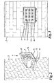
- FIG. 1 shows a perspective view of an embodiment of a stationary light-emitting unit 1 in the form of a radiator, which is fixedly mounted on a wall 2.
- the attachment takes place via a mounting bracket 10, which is provided with through openings 11, through which screws 12 engage for fastening to the wall 2.
- the light-emitting unit 1 is pivotally attached to the mounting bracket 10. To achieve this pivoting is transverse to the U-shaped configuration of the mounting bracket 10 extending away from the wall 2, a pivot axis 13 is provided which passes through both the mounting bracket 10 and the housing 14 of the light-emitting unit.
- the emission of the light-emitting unit 1 obliquely to a bottom, not shown, so directed obliquely downward with respect to the view shown.
- the light-emitting unit 1 can also be pivoted, for example in the in FIG. 2 shown approximately at right angles to the surface of the wall 2 standing direction.
- the light-emitting front surface 15 of the light-emitting unit 1 lies approximately parallel to the wall 2.
- FIG. 3 A frontal view of the front surface 15 and the wall 2 is in FIG. 3 shown.
- the light-emitting unit 1 is provided with twelve light-emitting devices in the form of LEDs 3, which are each surrounded by reflector devices 4.
- the twelve reflector devices 4 with centrally arranged LEDs 3 are arranged distributed with approximately the same distance from one another, in principle in the manner of a waffle pattern. As a result, a uniform emission of light via the front surface 15 of the light-emitting unit 1 is possible.
- a cover plate 16 is also provided to the outer end of the housing 14, the in FIG. 2 is merely indicated.
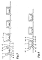
- FIG. 4 A detailed view of a circuit board 17 with the twelve LEDs and reflector devices arranged thereon is shown in a perspective view in FIG. 4 shown.
- the board 17 is advantageously designed as a heat-dissipating device.
- it consists of a good heat-conducting metal, such as aluminum.
- the reflector devices 4, the detail view in the FIGS. 7 and 8 are shown are attached to the board by plugging.
- the board 17 has a number of holes or openings 18 for the insertion of corresponding mounting feet of the reflector devices.
- the openings 18 are in FIG. 4 only to be seen in part in the FIGS. 5 and 6 however also shown.
- the mounting feet 40, 41 of the reflector devices 4 are best in the perspective view of the reflector device 4 from below in FIG. 8 to see.
- the mounting feet 40, 41 have respective projecting lugs 42. As a result, they hold themselves firmly in the openings 18 of the board 17.
- a subsequent removal or replacement of the reflector devices 4 is also possible, so unlatching and removing the reflector means 4.
- the two opposite outer walls 43, 44 of the reflector means 4 are pressed slightly towards each other and thus the projecting lugs 42 from the Verrastungsposition moved out, so that a removal of the reflector devices 4 away from the board is possible.
- spacer pins 45 are provided at two opposite corners, which provide a distance to the surface of the board 17 in the Verrastungsposition.
- the lower edge 46 of the two opposite outer walls 47, 48 is in each case stepped, that is, the outer walls 47, 48 are not formed uniformly high, but higher in the area of the spacer pins 45 and lower in the remaining area.
- a part of the two opposing outer walls 43, 44 is respectively formed lower than the area surrounding the two fixing feet 40, 41 and the corner portion of the spacer pins 45. This makes developing heat better be removed, so that it does not come under the reflector device to a heat accumulation.
- the reflector device 4 also has a truncated pyramid in a respective angle to each other and surrounding the LED 3 surfaces 49, 50, 51, 52. These surfaces are arranged not only to each other, but also to the outer walls 43, 44, 47, 48 at an angle.
- the surfaces 49 to 52 are connected to each other and also a respective surface with a respective outer wall on the upper side 53 of the reflector device 4.
- the surfaces 49 to 52 converge, with no uniform circumferential lower edge 57 is formed here, but a provided with two opposing Ausklingept 55, 56 lower edge. These notches overlap, as in FIG. 6 to see a lower part of the LED 3 and can also serve by the lifting of the reflector device from the surface of the board in the region of the LED to avoid heat build-up.
- the surfaces 49 to 52 are provided with a plurality of material recesses 58 and 59 superimposing, even act as small reflectors.
- a kind of texture or roughening of the surface of the reflector device 4 is created by which the incident light is further scattered, so that otherwise possibly forming patterns in the light distribution can be substantially compensated .
- Such a kind of roughening of the surface of the reflector device may be provided on the entire surface of the reflector device or only on a partial surface, as shown.
- angles of the surfaces 49 to 52 to one another determine the light emission angle of the light emitting devices or LEDs 3 and thus also the total emission surface of the light emitting unit 1, formed by the in the embodiment shown twelve light emitting devices or LEDs 3 in conjunction with the reflector means 4 and taking into account the further scattering of the emitted light by the advantageously provided surface irregularities of the reflecting surfaces 49 to 52.
- a kind of prism having a plurality of surfaces may be provided here.
- each other surfaces 49 to 52 and reflector devices in the form of small parabolic mirrors can be provided, in which the LEDs are arranged centrally in the parabolic mirrors.
- flat reflector devices 4 can be provided, which thus provide an angle of their surfaces to each other by about 180 degrees. In either case it is possible to provide a planar as well as an uneven surface of the reflector device.
- the LEDs are each centrally located in the reflector devices 4.
- the mounting feet 40, 41 can the FIG. 5 be taken very well in their Verrastungsposition.
- FIG. 6 can be seen that the LEDs 3 protrude with its lower portion 30 of the board 17 on the bottom of this. So here is a connection of the LEDs to a power supply, which is not shown possible.
- the board 17 can be provided with the LEDs arranged thereon and reflector devices separable from the power unit of the light-emitting unit 1.
- Such a separation possibility makes it possible to easily exchange the printed circuit board with LEDs and reflector devices without having to remove the power section from a wall or other fastening point.
- For releasably securing the board to the power unit openings 21 are provided in this, so that for example a fastening can be done by screwing about this.
- the surface 19 of the board 17 can also be formed as a reflector device, for example by providing a reflective surface coating 20. This is in FIGS. 5 and 6 merely hinted.
- the reflector devices may consist of a metal, but in principle also of a reflective plastic material, for example a corresponding surface-coated plastic material or a combination of different materials.
- care is taken to ensure that the material used is temperature-resistant, since a high temperature development in the light emission of, for example, only 12 watts is achieved especially with powerful light-emitting units or emitters.
- a respective reflector device is assigned to a light-emitting device.
- the reflector device can have different dimensions and dimensions.
- a reflector device can also be assigned, for example, to two light-emitting devices, particularly good results being achieved when assigning a reflector device to a respective light-emitting device.
Landscapes
- Engineering & Computer Science (AREA)
- General Engineering & Computer Science (AREA)
- Architecture (AREA)
- Non-Portable Lighting Devices Or Systems Thereof (AREA)
- Arrangement Of Elements, Cooling, Sealing, Or The Like Of Lighting Devices (AREA)
- Planar Illumination Modules (AREA)
Applications Claiming Priority (1)
| Application Number | Priority Date | Filing Date | Title |
|---|---|---|---|
| DE202009014384U DE202009014384U1 (de) | 2009-10-24 | 2009-10-24 | Stationäre Licht aussendende Einheit |
Publications (2)
| Publication Number | Publication Date |
|---|---|
| EP2314908A2 true EP2314908A2 (fr) | 2011-04-27 |
| EP2314908A3 EP2314908A3 (fr) | 2013-06-12 |
Family
ID=43532929
Family Applications (1)
| Application Number | Title | Priority Date | Filing Date |
|---|---|---|---|
| EP10013847.8A Withdrawn EP2314908A3 (fr) | 2009-10-24 | 2010-10-21 | Unité émettrice de lumière stationnaire |
Country Status (2)
| Country | Link |
|---|---|
| EP (1) | EP2314908A3 (fr) |
| DE (1) | DE202009014384U1 (fr) |
Cited By (3)
| Publication number | Priority date | Publication date | Assignee | Title |
|---|---|---|---|---|
| CN102401278A (zh) * | 2011-07-20 | 2012-04-04 | 苏州晶雷光电照明科技有限公司 | Led建筑轮廓荧光灯 |
| CN103335247A (zh) * | 2013-06-21 | 2013-10-02 | 周玉龙 | 一种洗窗灯 |
| WO2015132868A1 (fr) * | 2014-03-04 | 2015-09-11 | 日本コルモ株式会社 | Lampe à diodes électroluminescentes de type à volet |
Family Cites Families (3)
| Publication number | Priority date | Publication date | Assignee | Title |
|---|---|---|---|---|
| JP3787146B1 (ja) * | 2005-08-30 | 2006-06-21 | 株式会社未来 | 照明装置 |
| US20080219000A1 (en) * | 2007-03-09 | 2008-09-11 | Chen-Yueh Fan | Lampshade with at least one LED |
| MX2010004433A (es) * | 2007-10-25 | 2010-05-13 | Lsi Industries Inc | Reflector. |
-
2009
- 2009-10-24 DE DE202009014384U patent/DE202009014384U1/de not_active Expired - Lifetime
-
2010
- 2010-10-21 EP EP10013847.8A patent/EP2314908A3/fr not_active Withdrawn
Non-Patent Citations (1)
| Title |
|---|
| None |
Cited By (4)
| Publication number | Priority date | Publication date | Assignee | Title |
|---|---|---|---|---|
| CN102401278A (zh) * | 2011-07-20 | 2012-04-04 | 苏州晶雷光电照明科技有限公司 | Led建筑轮廓荧光灯 |
| CN103335247A (zh) * | 2013-06-21 | 2013-10-02 | 周玉龙 | 一种洗窗灯 |
| CN103335247B (zh) * | 2013-06-21 | 2015-09-09 | 周玉龙 | 一种洗窗灯 |
| WO2015132868A1 (fr) * | 2014-03-04 | 2015-09-11 | 日本コルモ株式会社 | Lampe à diodes électroluminescentes de type à volet |
Also Published As
| Publication number | Publication date |
|---|---|
| DE202009014384U1 (de) | 2011-03-10 |
| EP2314908A3 (fr) | 2013-06-12 |
Similar Documents
| Publication | Publication Date | Title |
|---|---|---|
| EP1154200B1 (fr) | Distributeur de lumière pour un système d'éclairage, système d'éclairage et utilisation d' un système d'éclairage | |
| EP2307793B1 (fr) | Dispositif d'eclairage | |
| EP1231429B1 (fr) | Dispositif d'illumination en couleur | |
| EP1843081B1 (fr) | Eclairage, en particulier éclairage d'intérieur | |
| EP2678603A1 (fr) | Dispositif d'éclairage | |
| DE102007059607A1 (de) | Wand- und/oder Deckenleuchte | |
| EP2236912A2 (fr) | Luminaire | |
| EP3037719A1 (fr) | Corps de lentille del destine a produire une quantite de lumiere directe et indirecte | |
| EP2177818A1 (fr) | Unité d'éclairage dotée d'une lanterne de rue | |
| DE10011304A1 (de) | Leuchte mit inhomogener Lichtabstrahlung | |
| DE202011108542U1 (de) | Leuchte, insbesondere Wand- und/oder Deckenleuchte | |
| EP3199869B1 (fr) | Dispositif d'éclairage | |
| EP3186543A1 (fr) | Luminaire suspendu sans châssis | |
| EP2314908A2 (fr) | Unité émettrice de lumière stationnaire | |
| DE102009044387B4 (de) | LED-Außenleuchte | |
| EP3283820B1 (fr) | Système optique et ensemble d'émission de lumière | |
| DE20004188U1 (de) | Leuchte | |
| DE9403361U1 (de) | Leuchten und Lichtlenkblende dafür | |
| DE112013006624T5 (de) | Beleuchtungsvorrichtung | |
| EP4063717A1 (fr) | Luminaire à fonction de refroidissement avant | |
| DE102009056904A1 (de) | LED-Leuchte | |
| EP1913302A1 (fr) | Feu pour vehicules automobiles | |
| EP2107297B1 (fr) | Eclairage, en particulier éclairage d'intérieur | |
| EP4107426B1 (fr) | Lampe allongée | |
| EP2716963B1 (fr) | Agencement de réflecteur |
Legal Events
| Date | Code | Title | Description |
|---|---|---|---|
| PUAI | Public reference made under article 153(3) epc to a published international application that has entered the european phase |
Free format text: ORIGINAL CODE: 0009012 |
|
| AK | Designated contracting states |
Kind code of ref document: A2 Designated state(s): AL AT BE BG CH CY CZ DE DK EE ES FI FR GB GR HR HU IE IS IT LI LT LU LV MC MK MT NL NO PL PT RO RS SE SI SK SM TR |
|
| AX | Request for extension of the european patent |
Extension state: BA ME |
|
| PUAL | Search report despatched |
Free format text: ORIGINAL CODE: 0009013 |
|
| AK | Designated contracting states |
Kind code of ref document: A3 Designated state(s): AL AT BE BG CH CY CZ DE DK EE ES FI FR GB GR HR HU IE IS IT LI LT LU LV MC MK MT NL NO PL PT RO RS SE SI SK SM TR |
|
| AX | Request for extension of the european patent |
Extension state: BA ME |
|
| RIC1 | Information provided on ipc code assigned before grant |
Ipc: F21Y 101/02 20060101ALI20130503BHEP Ipc: F21V 17/16 20060101ALN20130503BHEP Ipc: F21V 7/00 20060101ALI20130503BHEP Ipc: F21V 29/00 20060101ALN20130503BHEP Ipc: F21V 21/30 20060101ALN20130503BHEP Ipc: F21V 7/22 20060101ALN20130503BHEP Ipc: F21S 8/00 20060101AFI20130503BHEP Ipc: F21Y 105/00 20060101ALN20130503BHEP Ipc: F21V 23/02 20060101ALN20130503BHEP Ipc: F21V 7/05 20060101ALN20130503BHEP Ipc: F21W 131/10 20060101ALN20130503BHEP Ipc: F21V 7/06 20060101ALN20130503BHEP |
|
| STAA | Information on the status of an ep patent application or granted ep patent |
Free format text: STATUS: THE APPLICATION IS DEEMED TO BE WITHDRAWN |
|
| 18D | Application deemed to be withdrawn |
Effective date: 20131213 |