EP2314972A1 - Echangeur de chaleur - Google Patents
Echangeur de chaleur Download PDFInfo
- Publication number
- EP2314972A1 EP2314972A1 EP09766433A EP09766433A EP2314972A1 EP 2314972 A1 EP2314972 A1 EP 2314972A1 EP 09766433 A EP09766433 A EP 09766433A EP 09766433 A EP09766433 A EP 09766433A EP 2314972 A1 EP2314972 A1 EP 2314972A1
- Authority
- EP
- European Patent Office
- Prior art keywords
- cutting line
- line segment
- cut
- heat exchanger
- fins
- Prior art date
- Legal status (The legal status is an assumption and is not a legal conclusion. Google has not performed a legal analysis and makes no representation as to the accuracy of the status listed.)
- Granted
Links
Images



Classifications
-
- F—MECHANICAL ENGINEERING; LIGHTING; HEATING; WEAPONS; BLASTING
- F28—HEAT EXCHANGE IN GENERAL
- F28D—HEAT-EXCHANGE APPARATUS, NOT PROVIDED FOR IN ANOTHER SUBCLASS, IN WHICH THE HEAT-EXCHANGE MEDIA DO NOT COME INTO DIRECT CONTACT
- F28D1/00—Heat-exchange apparatus having stationary conduit assemblies for one heat-exchange medium only, the media being in contact with different sides of the conduit wall, in which the other heat-exchange medium is a large body of fluid, e.g. domestic or motor car radiators
- F28D1/02—Heat-exchange apparatus having stationary conduit assemblies for one heat-exchange medium only, the media being in contact with different sides of the conduit wall, in which the other heat-exchange medium is a large body of fluid, e.g. domestic or motor car radiators with heat-exchange conduits immersed in the body of fluid
- F28D1/04—Heat-exchange apparatus having stationary conduit assemblies for one heat-exchange medium only, the media being in contact with different sides of the conduit wall, in which the other heat-exchange medium is a large body of fluid, e.g. domestic or motor car radiators with heat-exchange conduits immersed in the body of fluid with tubular conduits
-
- F—MECHANICAL ENGINEERING; LIGHTING; HEATING; WEAPONS; BLASTING
- F28—HEAT EXCHANGE IN GENERAL
- F28F—DETAILS OF HEAT-EXCHANGE AND HEAT-TRANSFER APPARATUS, OF GENERAL APPLICATION
- F28F1/00—Tubular elements; Assemblies of tubular elements
- F28F1/10—Tubular elements and assemblies thereof with means for increasing heat-transfer area, e.g. with fins, with projections, with recesses
- F28F1/12—Tubular elements and assemblies thereof with means for increasing heat-transfer area, e.g. with fins, with projections, with recesses the means being only outside the tubular element
- F28F1/24—Tubular elements and assemblies thereof with means for increasing heat-transfer area, e.g. with fins, with projections, with recesses the means being only outside the tubular element and extending transversely
- F28F1/32—Tubular elements and assemblies thereof with means for increasing heat-transfer area, e.g. with fins, with projections, with recesses the means being only outside the tubular element and extending transversely the means having portions engaging further tubular elements
- F28F1/325—Fins with openings
-
- F—MECHANICAL ENGINEERING; LIGHTING; HEATING; WEAPONS; BLASTING
- F28—HEAT EXCHANGE IN GENERAL
- F28D—HEAT-EXCHANGE APPARATUS, NOT PROVIDED FOR IN ANOTHER SUBCLASS, IN WHICH THE HEAT-EXCHANGE MEDIA DO NOT COME INTO DIRECT CONTACT
- F28D1/00—Heat-exchange apparatus having stationary conduit assemblies for one heat-exchange medium only, the media being in contact with different sides of the conduit wall, in which the other heat-exchange medium is a large body of fluid, e.g. domestic or motor car radiators
- F28D1/02—Heat-exchange apparatus having stationary conduit assemblies for one heat-exchange medium only, the media being in contact with different sides of the conduit wall, in which the other heat-exchange medium is a large body of fluid, e.g. domestic or motor car radiators with heat-exchange conduits immersed in the body of fluid
- F28D1/04—Heat-exchange apparatus having stationary conduit assemblies for one heat-exchange medium only, the media being in contact with different sides of the conduit wall, in which the other heat-exchange medium is a large body of fluid, e.g. domestic or motor car radiators with heat-exchange conduits immersed in the body of fluid with tubular conduits
- F28D1/053—Heat-exchange apparatus having stationary conduit assemblies for one heat-exchange medium only, the media being in contact with different sides of the conduit wall, in which the other heat-exchange medium is a large body of fluid, e.g. domestic or motor car radiators with heat-exchange conduits immersed in the body of fluid with tubular conduits the conduits being straight
- F28D1/0535—Heat-exchange apparatus having stationary conduit assemblies for one heat-exchange medium only, the media being in contact with different sides of the conduit wall, in which the other heat-exchange medium is a large body of fluid, e.g. domestic or motor car radiators with heat-exchange conduits immersed in the body of fluid with tubular conduits the conduits being straight the conduits having a non-circular cross-section
- F28D1/05366—Assemblies of conduits connected to common headers, e.g. core type radiators
- F28D1/05391—Assemblies of conduits connected to common headers, e.g. core type radiators with multiple rows of conduits or with multi-channel conduits combined with a particular flow pattern, e.g. multi-row multi-stage radiators
-
- F—MECHANICAL ENGINEERING; LIGHTING; HEATING; WEAPONS; BLASTING
- F28—HEAT EXCHANGE IN GENERAL
- F28F—DETAILS OF HEAT-EXCHANGE AND HEAT-TRANSFER APPARATUS, OF GENERAL APPLICATION
- F28F1/00—Tubular elements; Assemblies of tubular elements
- F28F1/10—Tubular elements and assemblies thereof with means for increasing heat-transfer area, e.g. with fins, with projections, with recesses
- F28F1/12—Tubular elements and assemblies thereof with means for increasing heat-transfer area, e.g. with fins, with projections, with recesses the means being only outside the tubular element
- F28F1/126—Tubular elements and assemblies thereof with means for increasing heat-transfer area, e.g. with fins, with projections, with recesses the means being only outside the tubular element consisting of zig-zag shaped fins
- F28F1/128—Fins with openings, e.g. louvered fins
-
- F—MECHANICAL ENGINEERING; LIGHTING; HEATING; WEAPONS; BLASTING
- F28—HEAT EXCHANGE IN GENERAL
- F28F—DETAILS OF HEAT-EXCHANGE AND HEAT-TRANSFER APPARATUS, OF GENERAL APPLICATION
- F28F1/00—Tubular elements; Assemblies of tubular elements
- F28F1/10—Tubular elements and assemblies thereof with means for increasing heat-transfer area, e.g. with fins, with projections, with recesses
- F28F1/12—Tubular elements and assemblies thereof with means for increasing heat-transfer area, e.g. with fins, with projections, with recesses the means being only outside the tubular element
- F28F1/24—Tubular elements and assemblies thereof with means for increasing heat-transfer area, e.g. with fins, with projections, with recesses the means being only outside the tubular element and extending transversely
- F28F1/30—Tubular elements and assemblies thereof with means for increasing heat-transfer area, e.g. with fins, with projections, with recesses the means being only outside the tubular element and extending transversely the means being attachable to the element
-
- F—MECHANICAL ENGINEERING; LIGHTING; HEATING; WEAPONS; BLASTING
- F28—HEAT EXCHANGE IN GENERAL
- F28F—DETAILS OF HEAT-EXCHANGE AND HEAT-TRANSFER APPARATUS, OF GENERAL APPLICATION
- F28F1/00—Tubular elements; Assemblies of tubular elements
- F28F1/10—Tubular elements and assemblies thereof with means for increasing heat-transfer area, e.g. with fins, with projections, with recesses
- F28F1/12—Tubular elements and assemblies thereof with means for increasing heat-transfer area, e.g. with fins, with projections, with recesses the means being only outside the tubular element
- F28F1/24—Tubular elements and assemblies thereof with means for increasing heat-transfer area, e.g. with fins, with projections, with recesses the means being only outside the tubular element and extending transversely
- F28F1/32—Tubular elements and assemblies thereof with means for increasing heat-transfer area, e.g. with fins, with projections, with recesses the means being only outside the tubular element and extending transversely the means having portions engaging further tubular elements
-
- F—MECHANICAL ENGINEERING; LIGHTING; HEATING; WEAPONS; BLASTING
- F28—HEAT EXCHANGE IN GENERAL
- F28F—DETAILS OF HEAT-EXCHANGE AND HEAT-TRANSFER APPARATUS, OF GENERAL APPLICATION
- F28F1/00—Tubular elements; Assemblies of tubular elements
- F28F1/10—Tubular elements and assemblies thereof with means for increasing heat-transfer area, e.g. with fins, with projections, with recesses
- F28F1/12—Tubular elements and assemblies thereof with means for increasing heat-transfer area, e.g. with fins, with projections, with recesses the means being only outside the tubular element
- F28F1/34—Tubular elements and assemblies thereof with means for increasing heat-transfer area, e.g. with fins, with projections, with recesses the means being only outside the tubular element and extending obliquely
-
- F—MECHANICAL ENGINEERING; LIGHTING; HEATING; WEAPONS; BLASTING
- F28—HEAT EXCHANGE IN GENERAL
- F28F—DETAILS OF HEAT-EXCHANGE AND HEAT-TRANSFER APPARATUS, OF GENERAL APPLICATION
- F28F17/00—Removing ice or water from heat-exchange apparatus
- F28F17/005—Means for draining condensates from heat exchangers, e.g. from evaporators
Definitions
- the present invention relates to a heat exchanger provided with flat tubes and fins.
- Patent Literature 1 (PTL1) describes a heat exchanger that each of the fins includes a plurality of protruding portions protruded to the downstream of airflow and each of the protruding portions includes a cutout. Condensed dew, generated in the heat exchanger, gathers in the downstream of airflow and drops downwards through the cutouts. However, the condensed dew normally drops through the cutouts when becoming larger to naturally drop due to its weight. Otherwise, the condensed dew is accumulated in the heat exchanger.
- the condensed dew blocks ventilation and accordingly deteriorates heat exchange performance of the heat exchanger.
- the applicant of the present invention developed a heat exchanger having an enhanced drainage performance with respect to condensed dew.
- the heat exchanger has a structure that the fins are respectively interposed between given two adjacent planar portions while being protruded from the edges of the planar portions. Accordingly, condensed dew flows downwards through the protruded portions of the fins (see PTL 2).
- a heat exchanger includes flat tubes and a single or plurality of fins.
- the flat tubes are disposed in a plurality of tiers.
- Each of the flat tubes includes a planar portion vertically faced.
- Each of the fins is disposed in a wavily folded state in a ventilation space interposed between the flat tubes disposed on given two vertically adjacent tiers.
- Each of the fins includes a heat transfer portion and a cut-and-raised portion.
- the heat transfer portion has a folded portion joined to the planar portion of each of the flat tubes.
- the cut-and-raised portion is protruded from the ventilation space.
- the cut-and-raised portion is formed by raising a periphery of a cutting line segment when a material of the fins is wavily folded.
- the cutting line segment is set in a vicinity of a hypothetical center line of the folded portion before the material of the fins is wavily folded.
- the cutting line segment is formed by a combination of cutting line segments intersecting with the hypothetical center line or a combination of a cutting line segment intersecting with the hypothetical center line and a cutting line segment displaced with respect to the hypothetical center line.
- the cut-and-raised height of each cut-and-raised portion is increased.
- the cut-and-raised portions of the fins on given two vertically adjacent tiers thereby easily make contact with each other.
- the contact portion between the cut-and-raised portions thereon is increased. Consequently, condensed dew on the surfaces of the fins disposed on the upper tiers easily flows onto the surfaces of the fins disposed on the lower tiers. In other words, good drainage performance is achieved.
- a heat exchanger relates to the heat exchanger according to the first aspect of the present invention.
- the cutting line segment includes a first cutting line segment and a second cutting line segment.
- the first cutting line segment intersects with the hypothetical center line.
- the second cutting line segment intersects with the hypothetical center line while being extended from a vicinity of a terminal of the first cutting line segment.
- the heat exchanger of the second aspect of the present invention long distance is produced from the base to the apex of each cut-and-raised portion. Accordingly, the contact amount is increased between the cut-and-raised portions of the fins disposed on given two vertically adjacent tiers.
- the heat exchanger of the third aspect of the present invention long distance is produced between the base of each cut-and-raised portion and the upwardly or downwardly faced edge of each cut-and-raised portion. Accordingly, the contact amount is further increased between the cut-and-raised portions of the fins disposed on given two vertically adjacent tiers.
- a heat exchanger relates to the heat exchanger according to the first aspect of the present invention.
- the cutting line segment includes a first cutting line segment, a second cutting line segment, a third cutting line segment, and a fourth cutting line segment.
- the first cutting line segment intersects with the hypothetical center line.
- the second cutting line does not intersect with the hypothetical center line while being extended from a vicinity of a terminal of the first cutting line segment.
- the third cutting line segment intersects with the hypothetical center line while being extended from a vicinity of a terminal of the second cutting line segment.
- the fourth cutting line segment does not intersect with the hypothetical center line while being extended from a vicinity of a terminal of the third cutting line segment.
- two cut-and-raised portions are formed in a periphery of the cutting line segment. Therefore, high contact reliability is achieved between the cut-and-raised portions of the fins disposed on given two vertically adjacent tiers.
- the cut-and-raised height of each cut-and-raised portion is increased.
- the cut-and-raised portions of the fins on given two vertically adjacent tiers thereby easily make contact with each other.
- the contact portion between the cut-and-raised portions thereon is increased. Consequently, condensed dew on the surfaces of the fins disposed on the upper tiers easily flows onto the surfaces of the fins disposed on the lower tiers. In other words, good drainage performance is achieved.
- the heat exchanger of the third aspect of the present invention long distance is produced between the base of each cut-and-raised portion and the upwardly or downwardly faced edge of each cut-and-raised portion. Accordingly, the contact amount is further increased between the cut-and-raised portions of the fins disposed on given two vertically adjacent tiers. Consequently, condensed dew easily flows along the cut-and-raised portions.
- Fig. 1 is an external perspective view of a heat exchanger according to the exemplary embodiment of the present invention.
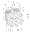
- Fig. 2 is an enlarged perspective view of a section A in Fig. 1 .
- a heat exchanger 10 includes flat tubes 11, wavy fins 12, and headers 15.
- the flat tubes 11 are molded using aluminum or aluminum alloy. Each flat tube 11 includes a planar portion 11a and a plurality of refrigerant flow paths 11b (see Fig. 2 ). The planar portion 11 a functions as a heat transfer surface, whereas the refrigerant flow paths 11b allow refrigerant to flow therethrough. As illustrated in Fig. 2 , the flat tubes 11 are disposed in a plurality of tiers while the planar portions 11a thereof are respectively vertically faced.
- a group of the louvers 12c positioned on the upstream of the center part of each transfer surface 12a, is slanted for allowing air to flow from the second face to the first face.
- a group of the louvers 12c positioned on the downstream of the center of each transfer surface 12a, is slanted for allowing air to flow from the first face to the second face.
- the headers 15 are coupled to the both ends of the respective flat tubes 11 vertically disposed in a plurality of tiers.
- the right-side header is referred to as "a first header 151" while the left-side header is referred to as "a second header 152" for convenience of explanation.
- the first and second headers 151, 152 have functions of: supporting the flat tubes 11; guiding refrigerant to the refrigerant flow paths 11b of the flat tubes 11; and gathering the refrigerant flowed out of the refrigerant flow paths 11b.
- refrigerant flows into the first header 151 through an inlet 151a. Subsequently, the refrigerant is roughly equally distributed into the respective refrigerant flow paths 11b of the flat tube 11 disposed on the highest tier, and flows towards the second header 152. When reaching the second header 152, the refrigerant is roughly equally distributed into the respective refrigerant flow paths 11b of the flat tube 11 disposed on the second highest tier, and flows towards the first header 151. Similarly, the refrigerant within the flat tubes 11 on the subsequent odd-numbered tiers flows towards the second header 152, whereas the refrigerant within the flat tubes 11 on the subsequent even-numbered tiers flows towards the first header 151. Finally, the refrigerant within the flat tube 11 on the lowest even-numbered tier flows towards the first header 151. The refrigerant gathers in the first header 151, and flows out of an outlet 151b.
- the surface of the heat exchanger has poor drainage performance when the respective flat tubes 11 are disposed while the planar portions 11a are vertically faced.
- the heat exchanger is used as an evaporator, accumulated condensed dew blocks airflow. Accordingly, heat exchange performance of the heat exchanger may be deteriorated.
- each wavy fin 12 is set to be greater than the width of each flat tube 11 as illustrated in Fig. 2 .
- the both ends of each wavy fin 12 are protruded out of the ventilation space. Condensed dew thereby flows downwards through the both ends of each wavy fin 12. Consequently, condensed dew is prevented from being accumulated on the wavy fins 12.
- water guide portions 12d are hereinafter referred to as "water guide portions 12d".
- the cut-and-raised portions 12b are formed (i.e., cut and raised) from a plate material when the plate material is wavily folded for forming the wavy fins 12.
- the cut-and-raised portions 12b will be hereinafter explained with reference to figures.
- Fig. 3 is a plan view of the wavy fins of a pre-wavily-folded state.
- the wavy fins 12 of a pre-folded state include a plurality of groups of the louvers 12c longitudinally formed thereon at equal intervals.
- An area, interposed between given two adjacent groups of the louvers 12c, is respectively changed into the valley portion 12g or the mountain portion 12h after bending of the wavy fins 12.
- the area will be hereinafter referred to as "a prospective folded area”.
- first cutting line segments 121 are set in positions separated inwards from the both edges of the prospective folded area at a predetermined distance.
- the first cutting line segments 121 are perpendicular to a hypothetical center line X of the prospective folded area.
- An arbitrary length may be set for each first cutting line segment 121 as long as the length is roughly equal to the thickness of each flat tube 11.
- second cutting line segments 122 are set to intersect with the hypothetical center line X.
- Each second cutting line segment 122 is extended from a terminal of each first cutting line segment 121 towards an edge of the prospective folded area.
- the first and second cutting line segments 121, 122 will be hereinafter inclusively referred to as "cutting line segments 120".
- each prospective folded area When each prospective folded area is actually folded in a mountain shape or a valley shape, an acute triangle portion formed by each first cutting line segment 121 and each second cutting line segment 122 and another acute triangle portion formed by each second cutting line segment 122 and each edge of the prospective folded area are both cut and raised. Accordingly, the both triangle portions are formed as the cut-and-raised portions 12b.
- the cut-and-raised portions 12b are protruded upwards or downwards as illustrated in Fig. 2 . Therefore, the cut-and-raised portions 12b of the wavy fins 12 on given two vertically adjacent tiers make contact with each other.
- condensed dew flows downwards along the water guide 12d of each wavy fin 12 on the upper one of the given two vertically adjacent tiers. Further, condensed dew flows from the cut-and-raised portion 12b of each wavy 12 thereon to the cut-and-raised portion 12b of each wavy fin 12 on the lower one of the given two vertically adjacent tiers. Yet further, condensed dew flows downwards through the water guide 12d of each wavy fin 12 on the lower one of the given two vertically adjacent tiers.
- first cutting line segments 131 are set in positions separated inwards from the both edges of the prospective folded area at a predetermined distance.
- the first cutting line segments 131 are perpendicular to a hypothetical center line X of the prospective folded area.
- An arbitrary length may be set for each first cutting line segment 131 as long as the length is roughly equal to the thickness of each flat tube 11.
- second cutting line segments 132 are set to be in parallel to the hypothetical center line X.
- Each second cutting line segment 132 is extended from a terminal of each first cutting line segment 131 to an edge of the prospective folded area.
- the first and second cutting line segment 131, 132 will be hereinafter inclusively referred to as "cutting line segments 130".
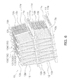
- FIG. 6 is a perspective view of a heat exchanger according to a second modification.
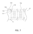
- Fig. 7 is a plan view of wavy fins of a pre-wavily-folded state in the heat exchanger according to the second modification.
- first cutting line segments 131 are set in positions separated inwards from the both edges of the prospective folded area at a predetermined distance.
- the first cutting line segments 131 are perpendicular to a hypothetical center line X of the prospective folded area.
- An arbitrary length may be set for each first cutting line segment 131 as long as the length is roughly equal to the thickness of each flat tube 11.
- third cutting lines 133 are set in each prospective folded area. Each third cutting line segment 133 is extended from a terminal of each second cutting line segment 132. Each third cutting line segment 133 is set to be in parallel to each first cutting line segment 131. The length of each third cutting line segment 133 is equal to the length of each first cutting line segment 131.
- a single cut-and-raised portion 12b is only formed in a periphery of the cutting line segments as illustrated in Fig. 4 .
- large contact area is formed between the cut-and-raised portions 12b of the wavy fins 12 on given two vertically adjacent tiers. Therefore, the contact area is greater than that in the aforementioned exemplary embodiment.
Landscapes
- Engineering & Computer Science (AREA)
- Physics & Mathematics (AREA)
- Thermal Sciences (AREA)
- Mechanical Engineering (AREA)
- General Engineering & Computer Science (AREA)
- Geometry (AREA)
- Heat-Exchange Devices With Radiators And Conduit Assemblies (AREA)
Applications Claiming Priority (2)
| Application Number | Priority Date | Filing Date | Title |
|---|---|---|---|
| JP2008162062A JP5320846B2 (ja) | 2008-06-20 | 2008-06-20 | 熱交換器 |
| PCT/JP2009/002756 WO2009153985A1 (fr) | 2008-06-20 | 2009-06-17 | Échangeur de chaleur |
Publications (3)
| Publication Number | Publication Date |
|---|---|
| EP2314972A1 true EP2314972A1 (fr) | 2011-04-27 |
| EP2314972A4 EP2314972A4 (fr) | 2014-03-26 |
| EP2314972B1 EP2314972B1 (fr) | 2017-12-20 |
Family
ID=41433903
Family Applications (1)
| Application Number | Title | Priority Date | Filing Date |
|---|---|---|---|
| EP09766433.8A Active EP2314972B1 (fr) | 2008-06-20 | 2009-06-17 | Echangeur de chaleur |
Country Status (7)
| Country | Link |
|---|---|
| US (1) | US8910703B2 (fr) |
| EP (1) | EP2314972B1 (fr) |
| JP (1) | JP5320846B2 (fr) |
| KR (1) | KR20110017458A (fr) |
| CN (1) | CN102047064B (fr) |
| AU (1) | AU2009261466B2 (fr) |
| WO (1) | WO2009153985A1 (fr) |
Families Citing this family (28)
| Publication number | Priority date | Publication date | Assignee | Title |
|---|---|---|---|---|
| JP4988015B2 (ja) * | 2010-07-20 | 2012-08-01 | シャープ株式会社 | 熱交換器及びそれを搭載した空気調和機 |
| JP5012972B2 (ja) * | 2010-07-30 | 2012-08-29 | ダイキン工業株式会社 | 熱交換器の曲げ加工方法及び熱交換器 |
| GB2484300B (en) * | 2010-10-05 | 2016-08-10 | Frenger Systems Ltd | Improvements in or relating to heat exchangers for air conditioning systems |
| KR101313347B1 (ko) | 2011-01-21 | 2013-10-01 | 다이킨 고교 가부시키가이샤 | 열교환기 및 공기 조화기 |
| CN103339457A (zh) * | 2011-01-21 | 2013-10-02 | 大金工业株式会社 | 热交换器及空调装置 |
| CN103299149B (zh) * | 2011-01-21 | 2015-04-29 | 大金工业株式会社 | 热交换器及空调机 |
| JP5569409B2 (ja) * | 2011-01-21 | 2014-08-13 | ダイキン工業株式会社 | 熱交換器および空気調和機 |
| JP2012154492A (ja) * | 2011-01-21 | 2012-08-16 | Daikin Industries Ltd | 熱交換器及び空気調和機 |
| KR101451056B1 (ko) | 2011-01-21 | 2014-10-16 | 다이킨 고교 가부시키가이샤 | 열교환기 및 공기 조화기 |
| JP5257485B2 (ja) | 2011-05-13 | 2013-08-07 | ダイキン工業株式会社 | 熱交換器 |
| JP2012241973A (ja) * | 2011-05-19 | 2012-12-10 | Daikin Industries Ltd | ブリッジ付き波形フィン積層熱交換器及びその製造方法 |
| JP5678392B2 (ja) * | 2011-06-16 | 2015-03-04 | 日本軽金属株式会社 | コルゲートフィン式熱交換器の排水構造 |
| JP5403029B2 (ja) * | 2011-10-07 | 2014-01-29 | ダイキン工業株式会社 | 冷凍装置 |
| CN103090713B (zh) * | 2011-11-07 | 2016-03-02 | 株式会社T.Rad | 热交换器 |
| JP5246322B2 (ja) * | 2011-12-14 | 2013-07-24 | ダイキン工業株式会社 | 熱交換器 |
| JP5796518B2 (ja) * | 2012-03-06 | 2015-10-21 | 株式会社デンソー | 冷媒蒸発器 |
| ES2627555T3 (es) * | 2013-02-13 | 2017-07-28 | Carrier Corporation | Intercambiador de calor con tubos aplanados y múltiples bancos |
| WO2014125825A1 (fr) * | 2013-02-18 | 2014-08-21 | 株式会社デンソー | Échangeur de chaleur et procédé de production pour celui-ci |
| US20150144309A1 (en) * | 2013-03-13 | 2015-05-28 | Brayton Energy, Llc | Flattened Envelope Heat Exchanger |
| KR102218301B1 (ko) * | 2013-07-30 | 2021-02-22 | 삼성전자주식회사 | 열교환기 및 그 코르게이트 핀 |
| JP6327271B2 (ja) * | 2015-04-17 | 2018-05-23 | 株式会社デンソー | 熱交換器 |
| KR20170015146A (ko) * | 2015-07-31 | 2017-02-08 | 엘지전자 주식회사 | 열교환기 |
| US11041676B2 (en) * | 2015-07-31 | 2021-06-22 | Lg Electronics Inc. | Heat exchanger |
| CN205352165U (zh) * | 2015-12-16 | 2016-06-29 | 杭州三花微通道换热器有限公司 | 换热器芯体和具有它的换热器 |
| JP7169119B2 (ja) * | 2018-06-19 | 2022-11-10 | 株式会社Soken | 熱交換器 |
| JP2021110511A (ja) * | 2020-01-14 | 2021-08-02 | マーレベーアサーマルシステムズジャパン株式会社 | ヒートポンプ式冷凍サイクル用室外熱交換器 |
| KR20210097423A (ko) * | 2020-01-30 | 2021-08-09 | 엘지전자 주식회사 | 열교환기 |
| CN116255854A (zh) * | 2021-12-09 | 2023-06-13 | 浙江盾安热工科技有限公司 | 翅片结构及换热器 |
Family Cites Families (11)
| Publication number | Priority date | Publication date | Assignee | Title |
|---|---|---|---|---|
| JPS58188569U (ja) * | 1982-06-10 | 1983-12-14 | 東洋ラジエ−タ−株式会社 | 冷媒蒸発器 |
| JPS5918179U (ja) * | 1982-07-26 | 1984-02-03 | カルソニックカンセイ株式会社 | エバポレ−タ |
| JPH0396582U (fr) * | 1989-12-27 | 1991-10-02 | ||
| JPH0755380A (ja) * | 1993-06-07 | 1995-03-03 | Nippondenso Co Ltd | 熱交換器 |
| US5462113A (en) * | 1994-06-20 | 1995-10-31 | Flatplate, Inc. | Three-circuit stacked plate heat exchanger |
| JPH09101092A (ja) * | 1995-10-04 | 1997-04-15 | Calsonic Corp | エバポレータ |
| US5787972A (en) * | 1997-08-22 | 1998-08-04 | General Motors Corporation | Compression tolerant louvered heat exchanger fin |
| CN2837762Y (zh) * | 2005-09-26 | 2006-11-15 | 郭朝诚 | 交换器结构 |
| JP4946348B2 (ja) | 2006-10-19 | 2012-06-06 | ダイキン工業株式会社 | 空気熱交換器 |
| US20090173479A1 (en) * | 2008-01-09 | 2009-07-09 | Lin-Jie Huang | Louvered air center for compact heat exchanger |
| CN101619950B (zh) * | 2009-08-13 | 2011-05-04 | 三花丹佛斯(杭州)微通道换热器有限公司 | 翅片和具有该翅片的换热器 |
-
2008
- 2008-06-20 JP JP2008162062A patent/JP5320846B2/ja active Active
-
2009
- 2009-06-17 US US12/997,076 patent/US8910703B2/en active Active
- 2009-06-17 WO PCT/JP2009/002756 patent/WO2009153985A1/fr not_active Ceased
- 2009-06-17 KR KR1020117001448A patent/KR20110017458A/ko not_active Ceased
- 2009-06-17 CN CN2009801204889A patent/CN102047064B/zh active Active
- 2009-06-17 EP EP09766433.8A patent/EP2314972B1/fr active Active
- 2009-06-17 AU AU2009261466A patent/AU2009261466B2/en active Active
Also Published As
| Publication number | Publication date |
|---|---|
| US8910703B2 (en) | 2014-12-16 |
| US20110139428A1 (en) | 2011-06-16 |
| EP2314972A4 (fr) | 2014-03-26 |
| AU2009261466A1 (en) | 2009-12-23 |
| EP2314972B1 (fr) | 2017-12-20 |
| CN102047064A (zh) | 2011-05-04 |
| JP2010002138A (ja) | 2010-01-07 |
| CN102047064B (zh) | 2012-11-21 |
| KR20110017458A (ko) | 2011-02-21 |
| JP5320846B2 (ja) | 2013-10-23 |
| AU2009261466B2 (en) | 2012-08-02 |
| WO2009153985A1 (fr) | 2009-12-23 |
Similar Documents
| Publication | Publication Date | Title |
|---|---|---|
| EP2314972B1 (fr) | Echangeur de chaleur | |
| EP2857785B1 (fr) | Echangeur de chaleur et climatiseur | |
| JP4989979B2 (ja) | 熱交換器 | |
| EP2048465B1 (fr) | Échangeur thermique et climatiseur | |
| US20120227945A1 (en) | Free-draining finned surface architecture for heat exchanger | |
| CN103797326B (zh) | 波纹片式热交换器的排水结构 | |
| JP2010019534A (ja) | 熱交換器 | |
| CN104685313B (zh) | 空调机用翅片管式换热器 | |
| CN101592421A (zh) | 翅片管型热交换器 | |
| JP2013245884A (ja) | フィンチューブ熱交換器 | |
| US20090173479A1 (en) | Louvered air center for compact heat exchanger | |
| US20150377561A1 (en) | Multiple Bank Flattened Tube Heat Exchanger | |
| JPH10197173A (ja) | 熱交換器用偏平管及び熱交換器 | |
| JP2012251719A (ja) | コルゲートフィン式熱交換器の排水構造 | |
| JP2006112731A (ja) | 細径多管式熱交換器の細径伝熱管ユニット | |
| JP2010014329A (ja) | 熱交換器 | |
| CN114207374B (zh) | 热交换器 | |
| JP2008121950A (ja) | フィン付き熱交換器 | |
| EP3483544B1 (fr) | Échangeur de chaleur | |
| JP2008025855A (ja) | 熱交換器、空気調和装置および熱交換器の製造方法 | |
| JP2010002152A (ja) | 熱交換器、及び熱交換器の製造方法 | |
| JP2008025854A (ja) | 熱交換器および空調調和装置 | |
| JP2013213603A (ja) | コルゲートフィン式熱交換器の排水構造 |
Legal Events
| Date | Code | Title | Description |
|---|---|---|---|
| PUAI | Public reference made under article 153(3) epc to a published international application that has entered the european phase |
Free format text: ORIGINAL CODE: 0009012 |
|
| 17P | Request for examination filed |
Effective date: 20110113 |
|
| AK | Designated contracting states |
Kind code of ref document: A1 Designated state(s): AT BE BG CH CY CZ DE DK EE ES FI FR GB GR HR HU IE IS IT LI LT LU LV MC MK MT NL NO PL PT RO SE SI SK TR |
|
| AX | Request for extension of the european patent |
Extension state: AL BA RS |
|
| DAX | Request for extension of the european patent (deleted) | ||
| A4 | Supplementary search report drawn up and despatched |
Effective date: 20140221 |
|
| RIC1 | Information provided on ipc code assigned before grant |
Ipc: F28F 1/30 20060101AFI20140217BHEP Ipc: F28F 1/32 20060101ALI20140217BHEP |
|
| GRAP | Despatch of communication of intention to grant a patent |
Free format text: ORIGINAL CODE: EPIDOSNIGR1 |
|
| STAA | Information on the status of an ep patent application or granted ep patent |
Free format text: STATUS: GRANT OF PATENT IS INTENDED |
|
| INTG | Intention to grant announced |
Effective date: 20170404 |
|
| GRAS | Grant fee paid |
Free format text: ORIGINAL CODE: EPIDOSNIGR3 |
|
| GRAJ | Information related to disapproval of communication of intention to grant by the applicant or resumption of examination proceedings by the epo deleted |
Free format text: ORIGINAL CODE: EPIDOSDIGR1 |
|
| GRAL | Information related to payment of fee for publishing/printing deleted |
Free format text: ORIGINAL CODE: EPIDOSDIGR3 |
|
| STAA | Information on the status of an ep patent application or granted ep patent |
Free format text: STATUS: REQUEST FOR EXAMINATION WAS MADE |
|
| INTC | Intention to grant announced (deleted) | ||
| GRAR | Information related to intention to grant a patent recorded |
Free format text: ORIGINAL CODE: EPIDOSNIGR71 |
|
| STAA | Information on the status of an ep patent application or granted ep patent |
Free format text: STATUS: GRANT OF PATENT IS INTENDED |
|
| INTG | Intention to grant announced |
Effective date: 20171010 |
|
| GRAA | (expected) grant |
Free format text: ORIGINAL CODE: 0009210 |
|
| STAA | Information on the status of an ep patent application or granted ep patent |
Free format text: STATUS: THE PATENT HAS BEEN GRANTED |
|
| AK | Designated contracting states |
Kind code of ref document: B1 Designated state(s): AT BE BG CH CY CZ DE DK EE ES FI FR GB GR HR HU IE IS IT LI LT LU LV MC MK MT NL NO PL PT RO SE SI SK TR |
|
| REG | Reference to a national code |
Ref country code: GB Ref legal event code: FG4D |
|
| REG | Reference to a national code |
Ref country code: CH Ref legal event code: EP |
|
| REG | Reference to a national code |
Ref country code: IE Ref legal event code: FG4D |
|
| REG | Reference to a national code |
Ref country code: AT Ref legal event code: REF Ref document number: 956757 Country of ref document: AT Kind code of ref document: T Effective date: 20180115 |
|
| REG | Reference to a national code |
Ref country code: DE Ref legal event code: R096 Ref document number: 602009049999 Country of ref document: DE |
|
| REG | Reference to a national code |
Ref country code: NL Ref legal event code: MP Effective date: 20171220 |
|
| PG25 | Lapsed in a contracting state [announced via postgrant information from national office to epo] |
Ref country code: SE Free format text: LAPSE BECAUSE OF FAILURE TO SUBMIT A TRANSLATION OF THE DESCRIPTION OR TO PAY THE FEE WITHIN THE PRESCRIBED TIME-LIMIT Effective date: 20171220 Ref country code: NO Free format text: LAPSE BECAUSE OF FAILURE TO SUBMIT A TRANSLATION OF THE DESCRIPTION OR TO PAY THE FEE WITHIN THE PRESCRIBED TIME-LIMIT Effective date: 20180320 Ref country code: LT Free format text: LAPSE BECAUSE OF FAILURE TO SUBMIT A TRANSLATION OF THE DESCRIPTION OR TO PAY THE FEE WITHIN THE PRESCRIBED TIME-LIMIT Effective date: 20171220 Ref country code: FI Free format text: LAPSE BECAUSE OF FAILURE TO SUBMIT A TRANSLATION OF THE DESCRIPTION OR TO PAY THE FEE WITHIN THE PRESCRIBED TIME-LIMIT Effective date: 20171220 |
|
| REG | Reference to a national code |
Ref country code: LT Ref legal event code: MG4D |
|
| REG | Reference to a national code |
Ref country code: AT Ref legal event code: MK05 Ref document number: 956757 Country of ref document: AT Kind code of ref document: T Effective date: 20171220 |
|
| PG25 | Lapsed in a contracting state [announced via postgrant information from national office to epo] |
Ref country code: LV Free format text: LAPSE BECAUSE OF FAILURE TO SUBMIT A TRANSLATION OF THE DESCRIPTION OR TO PAY THE FEE WITHIN THE PRESCRIBED TIME-LIMIT Effective date: 20171220 Ref country code: GR Free format text: LAPSE BECAUSE OF FAILURE TO SUBMIT A TRANSLATION OF THE DESCRIPTION OR TO PAY THE FEE WITHIN THE PRESCRIBED TIME-LIMIT Effective date: 20180321 Ref country code: BG Free format text: LAPSE BECAUSE OF FAILURE TO SUBMIT A TRANSLATION OF THE DESCRIPTION OR TO PAY THE FEE WITHIN THE PRESCRIBED TIME-LIMIT Effective date: 20180320 Ref country code: HR Free format text: LAPSE BECAUSE OF FAILURE TO SUBMIT A TRANSLATION OF THE DESCRIPTION OR TO PAY THE FEE WITHIN THE PRESCRIBED TIME-LIMIT Effective date: 20171220 |
|
| REG | Reference to a national code |
Ref country code: FR Ref legal event code: PLFP Year of fee payment: 10 |
|
| PG25 | Lapsed in a contracting state [announced via postgrant information from national office to epo] |
Ref country code: NL Free format text: LAPSE BECAUSE OF FAILURE TO SUBMIT A TRANSLATION OF THE DESCRIPTION OR TO PAY THE FEE WITHIN THE PRESCRIBED TIME-LIMIT Effective date: 20171220 |
|
| PG25 | Lapsed in a contracting state [announced via postgrant information from national office to epo] |
Ref country code: CZ Free format text: LAPSE BECAUSE OF FAILURE TO SUBMIT A TRANSLATION OF THE DESCRIPTION OR TO PAY THE FEE WITHIN THE PRESCRIBED TIME-LIMIT Effective date: 20171220 Ref country code: ES Free format text: LAPSE BECAUSE OF FAILURE TO SUBMIT A TRANSLATION OF THE DESCRIPTION OR TO PAY THE FEE WITHIN THE PRESCRIBED TIME-LIMIT Effective date: 20171220 Ref country code: CY Free format text: LAPSE BECAUSE OF FAILURE TO SUBMIT A TRANSLATION OF THE DESCRIPTION OR TO PAY THE FEE WITHIN THE PRESCRIBED TIME-LIMIT Effective date: 20171220 Ref country code: EE Free format text: LAPSE BECAUSE OF FAILURE TO SUBMIT A TRANSLATION OF THE DESCRIPTION OR TO PAY THE FEE WITHIN THE PRESCRIBED TIME-LIMIT Effective date: 20171220 Ref country code: SK Free format text: LAPSE BECAUSE OF FAILURE TO SUBMIT A TRANSLATION OF THE DESCRIPTION OR TO PAY THE FEE WITHIN THE PRESCRIBED TIME-LIMIT Effective date: 20171220 |
|
| PG25 | Lapsed in a contracting state [announced via postgrant information from national office to epo] |
Ref country code: IT Free format text: LAPSE BECAUSE OF FAILURE TO SUBMIT A TRANSLATION OF THE DESCRIPTION OR TO PAY THE FEE WITHIN THE PRESCRIBED TIME-LIMIT Effective date: 20171220 Ref country code: RO Free format text: LAPSE BECAUSE OF FAILURE TO SUBMIT A TRANSLATION OF THE DESCRIPTION OR TO PAY THE FEE WITHIN THE PRESCRIBED TIME-LIMIT Effective date: 20171220 Ref country code: IS Free format text: LAPSE BECAUSE OF FAILURE TO SUBMIT A TRANSLATION OF THE DESCRIPTION OR TO PAY THE FEE WITHIN THE PRESCRIBED TIME-LIMIT Effective date: 20180420 Ref country code: AT Free format text: LAPSE BECAUSE OF FAILURE TO SUBMIT A TRANSLATION OF THE DESCRIPTION OR TO PAY THE FEE WITHIN THE PRESCRIBED TIME-LIMIT Effective date: 20171220 Ref country code: PL Free format text: LAPSE BECAUSE OF FAILURE TO SUBMIT A TRANSLATION OF THE DESCRIPTION OR TO PAY THE FEE WITHIN THE PRESCRIBED TIME-LIMIT Effective date: 20171220 |
|
| REG | Reference to a national code |
Ref country code: DE Ref legal event code: R097 Ref document number: 602009049999 Country of ref document: DE |
|
| PLBE | No opposition filed within time limit |
Free format text: ORIGINAL CODE: 0009261 |
|
| STAA | Information on the status of an ep patent application or granted ep patent |
Free format text: STATUS: NO OPPOSITION FILED WITHIN TIME LIMIT |
|
| 26N | No opposition filed |
Effective date: 20180921 |
|
| PG25 | Lapsed in a contracting state [announced via postgrant information from national office to epo] |
Ref country code: DK Free format text: LAPSE BECAUSE OF FAILURE TO SUBMIT A TRANSLATION OF THE DESCRIPTION OR TO PAY THE FEE WITHIN THE PRESCRIBED TIME-LIMIT Effective date: 20171220 |
|
| REG | Reference to a national code |
Ref country code: CH Ref legal event code: PL |
|
| PG25 | Lapsed in a contracting state [announced via postgrant information from national office to epo] |
Ref country code: SI Free format text: LAPSE BECAUSE OF FAILURE TO SUBMIT A TRANSLATION OF THE DESCRIPTION OR TO PAY THE FEE WITHIN THE PRESCRIBED TIME-LIMIT Effective date: 20171220 |
|
| REG | Reference to a national code |
Ref country code: BE Ref legal event code: MM Effective date: 20180630 |
|
| REG | Reference to a national code |
Ref country code: IE Ref legal event code: MM4A |
|
| PG25 | Lapsed in a contracting state [announced via postgrant information from national office to epo] |
Ref country code: LU Free format text: LAPSE BECAUSE OF NON-PAYMENT OF DUE FEES Effective date: 20180617 Ref country code: MC Free format text: LAPSE BECAUSE OF FAILURE TO SUBMIT A TRANSLATION OF THE DESCRIPTION OR TO PAY THE FEE WITHIN THE PRESCRIBED TIME-LIMIT Effective date: 20171220 |
|
| PG25 | Lapsed in a contracting state [announced via postgrant information from national office to epo] |
Ref country code: LI Free format text: LAPSE BECAUSE OF NON-PAYMENT OF DUE FEES Effective date: 20180630 Ref country code: CH Free format text: LAPSE BECAUSE OF NON-PAYMENT OF DUE FEES Effective date: 20180630 Ref country code: IE Free format text: LAPSE BECAUSE OF NON-PAYMENT OF DUE FEES Effective date: 20180617 |
|
| PG25 | Lapsed in a contracting state [announced via postgrant information from national office to epo] |
Ref country code: BE Free format text: LAPSE BECAUSE OF NON-PAYMENT OF DUE FEES Effective date: 20180630 |
|
| PG25 | Lapsed in a contracting state [announced via postgrant information from national office to epo] |
Ref country code: MT Free format text: LAPSE BECAUSE OF NON-PAYMENT OF DUE FEES Effective date: 20180617 |
|
| PG25 | Lapsed in a contracting state [announced via postgrant information from national office to epo] |
Ref country code: TR Free format text: LAPSE BECAUSE OF FAILURE TO SUBMIT A TRANSLATION OF THE DESCRIPTION OR TO PAY THE FEE WITHIN THE PRESCRIBED TIME-LIMIT Effective date: 20171220 |
|
| PG25 | Lapsed in a contracting state [announced via postgrant information from national office to epo] |
Ref country code: PT Free format text: LAPSE BECAUSE OF FAILURE TO SUBMIT A TRANSLATION OF THE DESCRIPTION OR TO PAY THE FEE WITHIN THE PRESCRIBED TIME-LIMIT Effective date: 20171220 Ref country code: HU Free format text: LAPSE BECAUSE OF FAILURE TO SUBMIT A TRANSLATION OF THE DESCRIPTION OR TO PAY THE FEE WITHIN THE PRESCRIBED TIME-LIMIT; INVALID AB INITIO Effective date: 20090617 |
|
| PG25 | Lapsed in a contracting state [announced via postgrant information from national office to epo] |
Ref country code: MK Free format text: LAPSE BECAUSE OF NON-PAYMENT OF DUE FEES Effective date: 20171220 |
|
| P01 | Opt-out of the competence of the unified patent court (upc) registered |
Effective date: 20230525 |
|
| PGFP | Annual fee paid to national office [announced via postgrant information from national office to epo] |
Ref country code: DE Payment date: 20250429 Year of fee payment: 17 |
|
| PGFP | Annual fee paid to national office [announced via postgrant information from national office to epo] |
Ref country code: GB Payment date: 20250501 Year of fee payment: 17 |
|
| PGFP | Annual fee paid to national office [announced via postgrant information from national office to epo] |
Ref country code: FR Payment date: 20250508 Year of fee payment: 17 |