EP2315340A1 - Gleichrichtermodul für elektrische Maschine und elektrische Maschine mit einem solchen Modul - Google Patents
Gleichrichtermodul für elektrische Maschine und elektrische Maschine mit einem solchen Modul Download PDFInfo
- Publication number
- EP2315340A1 EP2315340A1 EP10187011A EP10187011A EP2315340A1 EP 2315340 A1 EP2315340 A1 EP 2315340A1 EP 10187011 A EP10187011 A EP 10187011A EP 10187011 A EP10187011 A EP 10187011A EP 2315340 A1 EP2315340 A1 EP 2315340A1
- Authority
- EP
- European Patent Office
- Prior art keywords
- plate
- wafer
- base
- module according
- module
- Prior art date
- Legal status (The legal status is an assumption and is not a legal conclusion. Google has not performed a legal analysis and makes no representation as to the accuracy of the status listed.)
- Granted
Links
- 238000003466 welding Methods 0.000 claims abstract description 32
- 239000004020 conductor Substances 0.000 claims abstract description 5
- RYGMFSIKBFXOCR-UHFFFAOYSA-N Copper Chemical compound [Cu] RYGMFSIKBFXOCR-UHFFFAOYSA-N 0.000 claims description 8
- 229910052802 copper Inorganic materials 0.000 claims description 8
- 239000010949 copper Substances 0.000 claims description 8
- 238000002788 crimping Methods 0.000 claims description 8
- 229910052782 aluminium Inorganic materials 0.000 claims description 5
- XAGFODPZIPBFFR-UHFFFAOYSA-N aluminium Chemical compound [Al] XAGFODPZIPBFFR-UHFFFAOYSA-N 0.000 claims description 5
- 239000007769 metal material Substances 0.000 claims 1
- 230000002035 prolonged effect Effects 0.000 abstract 1
- 239000000463 material Substances 0.000 description 11
- 238000004804 winding Methods 0.000 description 10
- 229910052751 metal Inorganic materials 0.000 description 7
- 239000002184 metal Substances 0.000 description 7
- 238000005192 partition Methods 0.000 description 5
- 238000009423 ventilation Methods 0.000 description 4
- 210000000078 claw Anatomy 0.000 description 3
- 239000008188 pellet Substances 0.000 description 3
- 230000001681 protective effect Effects 0.000 description 3
- 239000004065 semiconductor Substances 0.000 description 3
- 239000007858 starting material Substances 0.000 description 3
- 239000002826 coolant Substances 0.000 description 2
- 210000003298 dental enamel Anatomy 0.000 description 2
- 230000005284 excitation Effects 0.000 description 2
- 238000004519 manufacturing process Methods 0.000 description 2
- 238000007747 plating Methods 0.000 description 2
- 238000011084 recovery Methods 0.000 description 2
- 239000011347 resin Substances 0.000 description 2
- 229920005989 resin Polymers 0.000 description 2
- 125000006850 spacer group Chemical group 0.000 description 2
- 229910001030 Iron–nickel alloy Inorganic materials 0.000 description 1
- FYYHWMGAXLPEAU-UHFFFAOYSA-N Magnesium Chemical compound [Mg] FYYHWMGAXLPEAU-UHFFFAOYSA-N 0.000 description 1
- 239000000853 adhesive Substances 0.000 description 1
- 230000001070 adhesive effect Effects 0.000 description 1
- 239000011324 bead Substances 0.000 description 1
- 239000002775 capsule Substances 0.000 description 1
- 239000000919 ceramic Substances 0.000 description 1
- FQMNUIZEFUVPNU-UHFFFAOYSA-N cobalt iron Chemical compound [Fe].[Co].[Co] FQMNUIZEFUVPNU-UHFFFAOYSA-N 0.000 description 1
- 230000000295 complement effect Effects 0.000 description 1
- 238000010276 construction Methods 0.000 description 1
- 230000003247 decreasing effect Effects 0.000 description 1
- 238000010586 diagram Methods 0.000 description 1
- 238000001125 extrusion Methods 0.000 description 1
- 239000012530 fluid Substances 0.000 description 1
- 230000017525 heat dissipation Effects 0.000 description 1
- 238000003754 machining Methods 0.000 description 1
- 229910052749 magnesium Inorganic materials 0.000 description 1
- 239000011777 magnesium Substances 0.000 description 1
- 238000012423 maintenance Methods 0.000 description 1
- 206010027175 memory impairment Diseases 0.000 description 1
- 230000007935 neutral effect Effects 0.000 description 1
- 230000002441 reversible effect Effects 0.000 description 1
- 239000007787 solid Substances 0.000 description 1
- 238000011144 upstream manufacturing Methods 0.000 description 1
- 238000005493 welding type Methods 0.000 description 1
Images




Classifications
-
- H—ELECTRICITY
- H05—ELECTRIC TECHNIQUES NOT OTHERWISE PROVIDED FOR
- H05K—PRINTED CIRCUITS; CASINGS OR CONSTRUCTIONAL DETAILS OF ELECTRIC APPARATUS; MANUFACTURE OF ASSEMBLAGES OF ELECTRICAL COMPONENTS
- H05K7/00—Constructional details common to different types of electric apparatus
- H05K7/20—Modifications to facilitate cooling, ventilating, or heating
- H05K7/2089—Modifications to facilitate cooling, ventilating, or heating for power electronics, e.g. for inverters for controlling motor
- H05K7/20909—Forced ventilation, e.g. on heat dissipaters coupled to components
-
- H—ELECTRICITY
- H02—GENERATION; CONVERSION OR DISTRIBUTION OF ELECTRIC POWER
- H02K—DYNAMO-ELECTRIC MACHINES
- H02K11/00—Structural association of dynamo-electric machines with electric components or with devices for shielding, monitoring or protection
- H02K11/04—Structural association of dynamo-electric machines with electric components or with devices for shielding, monitoring or protection for rectification
- H02K11/049—Rectifiers associated with stationary parts, e.g. stator cores
- H02K11/05—Rectifiers associated with casings, enclosures or brackets
-
- H—ELECTRICITY
- H02—GENERATION; CONVERSION OR DISTRIBUTION OF ELECTRIC POWER
- H02K—DYNAMO-ELECTRIC MACHINES
- H02K5/00—Casings; Enclosures; Supports
- H02K5/04—Casings or enclosures characterised by the shape, form or construction thereof
- H02K5/20—Casings or enclosures characterised by the shape, form or construction thereof with channels or ducts for flow of cooling medium
- H02K5/207—Casings or enclosures characterised by the shape, form or construction thereof with channels or ducts for flow of cooling medium with openings in the casing specially adapted for ambient air
Definitions
- the present invention relates to a current rectifying module for a polyphase rotating electrical machine, in particular an alternator or a motor starter-alternator, and a rotating electrical machine comprising such a module.
- Such a module is such a polyphase machine, in the form of an alternator or a polyphase alternator-starter with internal ventilation for a motor vehicle, are described in the document FR 2,911,444 in accordance with the preamble of claim 1.
- the machine comprises conventionally, for example as in the documents EP 515 259 and FR 2 602 925 , a housing carrying a stator surrounding a rotor, such as a claw rotor, integral with a rotor shaft rotatably mounted in the housing.
- the housing comprises at least two perforated flanges, called front bearing and rear bearing, annular and hollow, each bearing centrally a ball bearing for rotational mounting of the shaft.
- At least one excitation coil is associated with the rotor. This winding is for example connected by wire links to collector rings integral with the rear end of the rotor shaft. Brushes, carried by a brush holder integral with a voltage regulator, are allowed to rub on the rings.
- the stator has a grooved body carrying a stator winding through the grooves and extending on either side of the body to form buns.
- the stator winding comprises one or more windings per phase. These windings are obtained for example from a continuous coiled wire covered with enamel or from enamel-coated conductive segments, such as pins connected together by welding.
- the windings are connected in a star or in a triangle and have outlets connected to inputs belonging to a current recovery device, on the one hand, carried by one of the front and rear bearings and, on the other hand, having current rectifying elements, such as diodes, belonging to at least one ac rectifier bridge in direct current.
- a current recovery device carried by one of the front and rear bearings and, on the other hand, having current rectifying elements, such as diodes, belonging to at least one ac rectifier bridge in direct current.
- This device is capped by a perforated protective cover secured to the bearing.
- the number of phases depends on the applications. It is equal to or greater than three as described in the document WO 03/009452 , with the presence of one or two bridge rectifiers.
- the rear bearing 50 of annular and hollow shape, comprises a bottom 56, generally of transverse orientation with respect to the axis XX of the shaft 61 of the rotor 58, here with claws, carrying a rear fan 57 provided with blades 570.
- the bottom 56 has air inlet openings 51 and is extended at its outer periphery by an annular flange 55 generally axially oriented relative to the axis XX.
- the flange 55 has openings 53 for air outlet and internally houses the body 155 of the stator carrying a bun 156 implanted radially between the blades 570 and the openings 53, which comprise an axial portion affecting the rim 55 and a radial portion affecting the outer periphery of the bottom 56.
- This bun 156 belongs to the winding of the stator and carries the outputs of the windings of the phases, which each pass through a radial portion of an opening 53 or alternatively a specific opening made at the outer periphery of the bottom 56.
- the reference 52 designates a central cylindrical core defining the central opening of the bottom 56 and externally the openings 51 of air inlet.
- a capsule 62 is interposed between the outer periphery of the outer ring of the bearing 60.
- This reciprocating AC current is rectified into a DC current by the current rectifier device, in particular to recharge the vehicle battery and supply the consumers of the on-board vehicle network with direct current.
- a circulation of air between the openings 51 and 53 is achieved by the rotation of the fan 57 to cool the rectifier and the stator winding and ball bearings.
- the bearing 50 is metallic, here aluminum or alternatively based on magnesium. It is electrically connected to the ground and the negative terminal of the battery of the motor vehicle.
- the plate 10 is extended by a heat sink 16 integral with the plate 10, here with the aid of screws 92.
- This dissipator 16 has a base 19, extended inwards by the fins 18.
- a heat conducting element 17 is interposed between the dorsal face 102 of the plate 10 and the end face of the base 19.
- the element 17 consists of an embodiment in a sheet of plastic material or a thermo-conductive adhesive. Alternatively the element 17 is thermally insulating.
- the air passes through the fins 18 located vis-à-vis an opening 51 and it is for this reason that the fins are of different length to fit the shape of the openings 51.
- the module is well cooled .
- the diodes 93, 94 grouped in pairs, project outwardly with respect to the front face 103 of the plate 10. They are provided with a base, comprising a solid main part extended axially by a base having a fixing face for a semiconductor element 200 interposed between the base and the head of a rigid wire-shaped connection element called the tail or axis of the diode. Resin surrounds the head of the tail of the diode and the semiconductor element. This resin is integral with the base.
- the diode 94 is intended to be electrically connected to ground via the metal bearing 50, while the diode 93 is intended to be electrically connected to a terminal connected by a cable to the positive terminal of the battery.
- the electrical diagram of the figure 8 of the document FR 2,911,444 knowing that in this embodiment there are six modules (see figure 2 of this document).
- Each plate has tab 15 for fixing it by means of a screw 91 to the bottom 56.
- the screw passes through the lug 15 via an insulating barrel 199 to be screwed into a hole 150 in the bottom 56, connected to the mass, while the plate 10 is connected to the output of the relevant phase passing through in known manner to do the bottom 56.
- connection with a phase output is carried out using a washer or an electrically conductive tongue (see figures 7 and 12 of FR 2,911,444 ).
- the present invention aims to simplify the mounting of the current rectifier module.
- a current rectifying module for a polyphase rotating electrical machine with several phase outputs comprising an electrically conductive support plate for current rectifying elements, such as diodes, a phase of the rotating electrical machine, in which the plate is extended by a heat sink having a base integral with the plate, is characterized in that it comprises an electrically conductive and configured phase plate to be connected to the output of a phase of the machine, in that the plate is interposed between the base and the wafer less thick than the plate, in that the heat sink, the plate and the wafer are made of material electrically and thermally conductive and in that the base, the plate and the plate are assembled together by laser welding of the type by transparency.
- the heat sink, the plate and the wafer are also made of laser weldable material.
- the heat sink, the plate and the plate are metallic. They are for example aluminum or copper.
- a rotating electrical machine of the type indicated above is characterized in that it carries such a module.
- the wafer is less thick than the wafer.
- This wafer is thus relatively thin and therefore economical.
- the thinness of the wafer facilitates laser welding by transparency.
- this thinness facilitates assembly of the wafer with its associated phase output.
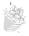
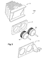
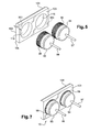
- FIG. 3 to 10 an embodiment of a module 100A according to the invention, which is dedicated to the current rectification of a phase of the polyphase rotating electrical machine and which replaces the module 100 of the figure 2 .
- the polyphase rotary electrical machine is therefore an alternator with internal ventilation, in particular for a motor vehicle, as in the figures 1 and 2 .
- the rear bearing 50 is modified at its openings 51 in the manner described hereinafter; the structure of the alternator is preserved.
- the dissipator 16, the plate 10 and the wafer 110 are made of electrically and thermally conductive material. They are also made of weldable material using a laser.
- the dissipator 16, the plate 10 and the wafer 110 are metallic, here aluminum, which is a good conductor of heat, just like copper.
- the wafer 110 of phase is configured to be connected to the output of a phase of the machine as described below.
- the base of the dissipator, the plate and the wafer are assembled together by laser welding type transparency. This weld passes through the wafer 110 ( figure 9 ) less thick than the plate 10.
- the plate 10 is in a characteristic interposed between the base 19 of the dissipator 16 and the wafer 110, which is less thick than the plate 10.
- the electrical function of the module 100A is carried out using the diodes 93, 94, of the plate 10 and the wafer 110, whereas the heat dissipation function is carried out mainly by the dissipator 16 arranged for the most part in the flow. air.
- This sink ( figure 4 ) has, as in the figures 1 and 2 , a base 19 extended internally by thin fins 18 in one piece with the base.
- This dissipator 16 has a generally trapezoidal shape whose large base is constituted by the base 19
- the fins 18 are obtained for example by extrusion and extend perpendicular to the base 19. They have decreasing lengths at the ends of the base 19 to give the dissipator a generally trapezoidal shape adapted to that of the openings 51 of the 50 bearing air passage, some of which are visible at figure 12 .
- These openings 51 are generally trapezoidal in shape, and are delimited internally by the central core 52, laterally by arms and externally the material of the bottom 56.
- Axial air passages are present between two consecutive fins 18, which are in correspondence with an opening 51 associated with the module 100A.
- the heatsinks 16 are thus implanted in the axial flow of air passing through the openings 51.
- the rotor of the machine rotates, there is created a circulation of air generated by the rotation of the fan 57 of the figure 1 .
- the air thus axially passes through the fins 18 and the openings 51.
- the modules are well cooled so that the polyphase rotating electric machine can work at higher temperatures.
- These fins 18 have, in the middle of the base, a constant length for forming an enlarged central zone 190 of the base 19.
- This zone 190 is provided with a through-hole 490 for figure 12 ) the passage of an electrically insulating sleeve 492, here made of plastic, traversed by a fastener 192, here a screw alternatively a rivet or bolts, for fixing the module 100A to the bottom 56.
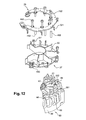
- Each module ( figures 11 and 12 ) is intended to be mounted here in a housing 26, 27 in two electrically insulating parts 26, 27, here plastic.
- One of these parts 27, called the lower part has a bottom 21 parallel to the bottom 56 of the bearing and is provided with openings 251 in correspondence with the openings 51 of the bottom 56 of this bearing.
- Partitions 30 extend perpendicular to the bottom 21 and define two consecutive openings 251.
- These partitions 30 are each connected at their inner periphery to an annular wall 129 and at their outer periphery to inclined walls 231.
- the other part 26 of the housing, said upper part extends to the outer periphery of the lower part 27. It covers the inclined walls 231 and forms a cover for the outer periphery of the portion 27.
- the modules are each mounted in a generally trapezoidal housing delimited by the partitions 30, the perforated bottom 21 and the upper portion 26. These housings are closed internally by the wall 129 and open at their outer periphery.
- the fins 18 of a module are mounted between the two partitions 30 of the housing which are high enough to electrically and thermally isolate the fins of two consecutive modules.
- the housing 26, 27 has a polygonal shape at its outer periphery.
- each housing of two projections 621 each intended to cooperate with a lateral end 191 ( figure 4 ), of the dorsal surface of the base 19 to hold the heatsink 16 and the module 100A in its housing.
- the parts 26 and 27 comprise electrical traces embedded in their plastic body and visible locally at their outer periphery so as to form radial-shaped brackets, respectively, 321 and 310 for electrical connection. respectively with the tail 96 of the diode 93 and the tail 97 of the diode 94.
- the parts 26 and 27 thus form respectively upper and lower connectors.
- the arms 321 and 322 are axially directed in the opposite direction and are circumferentially offset. These arms each have an inclined fold 350 for fixing the tails of the diodes by welding in order to make up the tolerances of the position of the tails of the diodes 93, 94.
- the arm trace 321 of the upper connector 26 also has annular apparent traces for contact with the enlarged zones 190 of the dissipator, as well as an apparent tongue 332 at one of these circumferential ends for its electrical connection with a terminal, referred to as a terminal B +, connected via a cable to the positive terminal of the battery.
- the connector 26 also has at its other circumferential end two visible parts 402, 403 for its connection with two apparent traces of the voltage regulator as described in document FR 2754 650 . To do this the parts 402, 403 each belong to a trace electrically connected to an enlarged area 190 of a base of a module.
- Some of the arms 310 have a hole for the passage of a screw 91 'screwing into a threaded hole 291 of the bottom 56 for connecting the trace with the mass.
- the arms 310 belong to two traces whose circumferential ends are fixed by screws 91 'in the tapped holes 291.
- the provisions described in the document can be used FR 2,911,444 , in particular figure 11 of it; the arms 310 being in this case removed and replaced by projections carried by the bearing 50 concerned.
- the tails 97 of the negative diodes 94 are in this case fixed by welding, crimping, snapping or stapling in the projections.
- five slots or four slots are provided when the alternator comprises respectively five and four phase outputs.
- the sleeve 492 extends projecting on either side of the faces of the central enlarged zone 190 of the base 19 to be fitted into complementary central holes in facing relation 520, 521 (FIG. figures 11 and 12 ) of the same housing formed respectively in the upper part 26 and in the bottom 21 of the part 27.
- the holes 520, 521 each belong to an ear that has the bottom 21 and the upper portion 26.
- the screws 192 each pass through a sleeve 492, engaged in a hole 490, to be screwed into a tapped hole 392 of the bottom 56 to fix the housing 26, 27 and the modules 100A, knowing that the sleeves 492 form a spacer between the bottom 21 and the portion 26.
- the projections 621 prevent the heatsink from rotating so that a single hole 490 is required.
- the holes 392 each belong to an ear that centrally presents the opening 51 concerned at its outer periphery. The openings 51 are thus modified with respect to those of the figure 1 to take into account the shape of the widened area 190.
- the front face of the base 19 has a notch 396-397-398 for receiving the plate 10, that is to say a removal of material to receive the plate 10.
- This notch is configured according to the shape of the plate 10. The depth of the notch is generally equal to the thickness of the plate.
- the notch here consists of a groove 396-397-398 for receiving the plate 10.
- the groove is adapted to the shape of the plate 10.
- This groove 396-397-398 is of U-shaped section and is delimited by a bottom 397, belonging to the front face of the base 19, and two parallel longitudinal edges 396, 398 perpendicular to the bottom 397. The front face of the base is thus notched for receiving the plate 10.
- the thickness e of the plate 10, here generally of rectangular shape, ( figure 5 and 8 to 10 ) adapted to the shape of the groove 396-397-398, is therefore in a characteristic less than the thickness e 'of the base 19 ( figure 4 ).
- the thickness of the plate 10 is generally equal to the depth of the groove 396-397-398, that is to say at the height of the edges 396, 398 of the groove.
- the width of the plate 10 is generally equal to the distance between the two parallel edges 396, 398 of one another.
- the length of the plate is generally equal to that of the longitudinal edges 396, 398.
- the longitudinal edges of the dorsal face 102 of the plate 10 are each provided with a chamfer 105 to facilitate the mounting of the plate to mounting set in the groove; these chamfers being adapted to cooperate with the longitudinal edges 396, 398 of the groove.
- the plate 10 constitutes a support, of the pair of diode 93, 94 each having a tail 96, 97.
- the plate 10 is a diode carrier.
- the diodes in one embodiment are soldered or other means on the plate 10.
- the plate 10 has two holes 119, namely a cylindrical hole 119 for each diode.
- the cylindrical pellets of the diodes 93, 94 are knurled in 198 to force fit the diodes in the holes 119.
- the plate 10 thus carries the diodes with good geometric precision; the knurled pellets 98 being by their knurling in engagement with the edges of the holes 119.
- diodes are called diodes of the type "press fit”.
- the caps of the diodes are flush with the dorsal surface of the plate so that the bottom of the caps of the diodes 93, 94 are in electrical contact with the bottom 397 of the groove as visible in FIG. figure 9 .
- a small clearance exists between the back face 102 of the plate and the bottom 397 of the groove.
- the dorsal face 102 of the plate 10 is also in contact with the bottom 397 of the groove.
- the dorsal face 102 of the plate 10 is in contact with the bottom 397 and a slight clearance exists between the caps of the diodes and the bottom 397.
- the thickness of the plate 10 is thus generally equal to the depth of the groove.
- the diodes 93, 94 are well cooled by the heatsinks.
- diodes are, according to a characteristic, located at 90 ° with respect to the axial orientation diodes of conventional alternators, which makes it possible to reduce the axial space requirement as in the case of figures 1 and 2 ; the tails 96, 97 of the diodes being parallel to the bottom 56 and directed outwards.
- the positive diode 93 is intended, via its shank 96, to be soldered here on an inclined fold 350 of the axially oriented end of an arm 321 electrically connected, in the aforementioned manner, to the positive terminal of the battery of the motor vehicle, while the negative diode 94 is intended, via its shank 97, to be welded to the inclined fold of the axial end of an arm 310 connected to ground ( figure 11 and 12 ) via the bottom 56 of the bearing 50.
- the tails 96, 97 are parallel to the fins 18 and perpendicular to the plate 10 and to the base 19.
- the axes of the tails 96, 97 are therefore of transverse orientation with respect to the axis XX of the figure 1 constituting the axis of the machine and the axis of rotation of the rotor thereof.
- This construction makes it possible to reduce the particularly axial space requirement of the module current rectifying device 100A belonging to the current rectifying arrangement, also including here the rear bearing 50, which supports the modules 110A.
- the temperature of the diodes 93, 94 is more homogeneous from one module to another.
- the wafer 110 is also generally of rectangular shape.
- the dorsal face of the wafer 110 is intended to come into contact with the end face 103 of the wafer 10 as visible in the Figures 8 to 10 .
- the length of the wafer 110 is generally equal to the length of the plate 10 and the groove 396-397-398 as visible in FIGS. figures 8 and 10 .
- the width of the wafer 110 is in a characteristic greater than that of the wafer 10.
- This width is generally equal to the width of the plate 10 and the generally increased groove of twice the thickness of an edge 396, 398 of the groove as visible in FIGS. Figures 8 to 10 .
- This plate 110 is intended to come opposite the edges 396, 398.
- the width of the plate is generally equal to the width of the base 19 being here slightly less than this width ( figure 9 ). In this embodiment a small clearance exists between the wafer and the edges 396, 398 of the groove ( figure 9 ) and this wafer 110 is in contact with the plate 10.
- the wafer 110 is in contact with the edges 396, 397.
- the thickness of the wafer is modified, the bases of the diodes being in contact with the bottom 397.
- the caps of the diodes and / or the dorsal surface of the plate are in contact with the bottom 397 of the groove, whereas the wafer 110 is in contact with the edges 397, 398 and the front face of the plate 10. All depends on the applications.
- the thickness of the wafer 110 being less than that of the plate 10, this wafer 110 is configured to be connected to one of the phase outputs of the polyphase stator of the machine.
- the wafer is easier to handle than the tab or the washer of the prior art. The risk of loss or forgetfulness is minimized so that the solution according to the invention is more reliable.
- This arrangement is advantageous because it facilitates the connection between the outputs of the axial orientation phases, as visible for example in the figure 1 of the document EP 0515 259 aforementioned, and platelets 110.
- the wafer carries a single piece at its inner periphery a thinner tab, that the tab 15 of the figure 2 , for its connection by welding with the exit of the phase
- each output of a phase is connected to an input 15 'carried by an arm 115 issuing from a circumferential end of the wafer 110, as visible for example in FIG. figure 6 .
- the inlet 15 'here consists of a generally U-shaped crimping lug, the branches of which are clamps folded in contact with a phase output. This phase output is stripped at its end to be fixed in favor of the clips of the leg 15 'crimped on this end.
- the inlet consists of an arm with a fold of the type of folds 350 for fixing by welding of the outlets.
- the arms 310, 321 have clips such as the inputs 15 for crimping the tails 96, 97 of the diodes.
- the arm 115 is in one piece with the wafer 110 and protrudes at the longitudinal end of the wafer adjacent to the diode 94 (FIG. figure 8 ), that is to say at one of the circumferential ends of the wafer.
- This arm 115 is circumferentially protruding.
- the arm is less than the width of the wafer 110.
- the inlet 15 ' is in one piece with the arm and constitutes the free end of the arm.
- the inlet 15 ' here in the form of a crimping tab, is easily deformable because the thickness of the wafer is less than that of the plate 10.
- the thickness of the metal wafer 110 is less than half the thickness of the metal wafer.
- the thickness of the wafer is 1 mm and that of the plate 10 3.5 mm.
- the thickness of the base 19 is example of 5.5 mm.
- the diameter of the caps of the diodes 93, 94 is generally equal to 14 mm
- the length of the base 19 is generally equal to 33.5 mm and its overall width of 20 mm.
- the edges 396, 398 generally have a thickness of 1 mm.
- the thickness of the wafer 110 is less than half the thickness of the wafer 10
- the thickness of the wafer is 0.8 mm or 1.6 mm.
- the wafer 110 is copper and the plate 10, and the heatsink aluminum.
- dissipator 16 and / or the plate are also copper.
- the arm 115 of a module 100A is inclined circumferentially to conform to the shape of the inclined wall 231 of the module housing ( figure 11 ). This avoids any interference between the attachment arm 310 of the diode 94 and the adjacent tab 15 '.
- the upper portion 26 of the housing provides a protective cover for the base 19, the plate 10, the wafer 110, the caps of the diodes 93, 94 and a portion of the tails 96, 97 of the diodes of a module 100A.
- the air passes through the fins 18, and the aligned openings 251, 51.
- the plate 10 equipped with the diodes is mounted in the groove 396-397-398, then the wafer 110 is placed on the plate ( figure 8 ).
- Welding is performed here along the two longitudinal edges 396, 398 of the groove to be as long as possible.
- the small thickness of the phase wafer 110 facilitates laser welding, which is fast and accurate.
- These transparency-type laser welding cords 201 pass through the wafer 110 and affect the longitudinal edges of the wafer 110 and, by their point, the longitudinal edges 396, 398 of the groove and of the wafer 10 as being better visible on the wafer 110. figure 9 .
- the laser welding provides an electrical connection between the components 16, 93-94, 10 and 110 of the module 110A.
- This welding ensures good heat conduction between the components 16, 93-94, 10 and 110 of the module 110A. This welding also ensures mechanical maintenance of the components 16, 93-94, 10 and 110 of the module 110A.
- This welding produces a mechanical plating of the caps of the diodes on the dissipator via the bottom 397 of the groove and thus a good thermal transfer of the diodes to the dissipator.
- This welding also creates a holding of the wafer 110 for fixing the output of the phase in question and therefore a mechanical plating of the wafer 110 on the plate and / or the dissipator, as well as a good conduction of heat.
- the clearance between the wafer 110 and the edges 396, 398 of the base 19 of the dissipator is eliminated so that the wafer in contact with the edges 396, 398 of the groove which improves the transfer of heat between the wafer and the dissipator.
- the welding is obtained for example by placing the dissipator and the plate in a hollow tool for housing the fins; said tool having shoulders for contact with the ends 191 of the dorsal face of the base 19 and vertical parts for contact with one of the pairs of the lateral edges of the plate 10 and the base of the dissipator 16 and this to a height less than the height of the base 19.
- a second tool presses the wafer 110, for example by means of a screw implanted between the two diodes 93, 94, in contact with the plate and comprises two lateral branches for positioning the wafer relative to the pair of lateral edges of the wafer. heatsink and plate considering that the first tool is engaged with the heatsink and the plate to a height less than that of the base.
- the plate has two projecting pins intended to engage each in a hole of the wafer.
- these dots and holes are shown in dotted lines, respectively at 300 and 301.
- the wafer 110 is thus prepositioned with respect to the plate 10. Any other connection by cooperation of shapes is possible.
- the second tool is thus simplified because it ensures a clamping function.
- the number of tools is duplicated to fix several modules.
- the tool is moved every time knowing that the welding of the laser type is fast.
- the plate has a tab for its attachment to the bottom as the figure 2 , so that the presence of an enlarged area 190 and a two-part housing is not mandatory.
- the module 100A is installed in place of the module 100 of the figures 1 and 2 .
- the plate 110 then has a notch for the passage of the bracket. This notch allows to preposition the wafer relative to the plate and this by cooperation of forms.
- One of the cords 201 is then in two parts. This is possible because one can achieve these two parts of cords by successive shots laser.
- cords can be split into at least two parts.
- the cords are therefore continuous or segmented.
- the end face of the base 19 has a notch in the form of a cavity for receiving the plate making it possible to preposition the plate.
- the groove is closed at each of its lateral ends by parallel transverse edges so that the cavity is rectangular in outline.
- the base, the plate and the plate by means of transverse weld seams.
- These cords may be associated with at least one portion of longitudinal welding bead.
- the groove or cavity may have another shape, which is a function of the shape of the plate 10, which in all cases has an oblong shape.
- the base 19 has at each of its longitudinal ends an enlarged area so that the dissipator is fixed at two points on the bearing.
- the 16 form dissipator trapezoidal, instead of fins 18, has slots of oblong shape delimited by strips of materials.
- the fins 18, instead of being thin, are in another thicker embodiment.
- the dissipator 16 may have another shape and comprise for example a plurality of holes.
- the dissipator 16 has a trapezoidal frame in which is mounted a strip of material in the form of accordion.
- the heatsink is alternatively copper, the fins, the slots, the holes and the frame being made by machining.
- the plate 10 and / or the wafer 110 are made of copper.
- the dissipator 16 the plate 10 and the wafer 110 are made of copper to facilitate laser welding by transparency.
- the plate, the wafer and / or the dissipator are nickel-iron alloy or cobalt-iron.
- the wafer 110 is alternatively sheet metal.
- the electric machine may alternatively as described above without brushes, as shown in the document FR 2,744,575 , so that the presence of the brush holder is not mandatory which can allow to mount an additional module.
- the internal fans are removed and replaced by an external fan so that the air passes axially through the housing of the figure 1 , without openings 53, through openings 51 made in the front and rear bearings.
- a centrifugal pump is used by the circulation of the air, which draws air into the alternator housing and delivers it through a channel.
- the invention is applicable to the case where the rotor is a rotor with salient poles possibly with magnets as described in the document WO 02/054566 .
- the claw rotor can be assembled by crimping to the shaft and have magnets between its teeth as visible in FIG. figure 2 of the document FR 2905 806 to which we will refer.
- Magnet solutions increase the power of the machine and are compatible with the modules according to the invention because they are well cooled.
- the solution according to the invention makes it possible to preserve the structure of the rotor.
- the housing 26, 27 is mounted on a perforated mezzanine carried by the bearing 50 as described in document WO 2004/040738 supra.
- the structures can be reversed so that, alternatively, the current rectifying device is carried not by the end face of the bearing of the machine housing but by the dorsal surface of the bearing forming a protective cover.
- the bearing concerned is elongated axially and it is the bottom 56 of the bearing which carries the housing for the rear bearing of the alternator; the slip rings being located upstream of the bottom 56 and the rear bearing.
- the housing of the machine may have more than two parts.
- the housing may comprise a front bearing, a rear bearing and an intermediate portion carrying the stator.
- the centrifugal fan 57 of the figure 1 is alternatively axial action so that the presence of the openings 53 is not mandatory.
- the machine is alternatively also cooled by fluid circulation.
- the invention is applicable to the case where the rotating electrical machine is associated with a fixed heat engine.
- the current rectifying elements 93, 94 are located at the outer periphery of the bottom 56 of the bearing concerned, outside the air inlet openings 51 so that these Openings or openings of the bearing are disengaged and the radial length of the fins 18 or slits of the dissipator is transversely as long as possible.
- the tails 96, 97 of the diodes 93, 94 are in the figures of identical length. In a variant, the tails are of different length. This is possible thanks to the configuration of the arms 310, 321, which can be of different axial and / or radial size to adapt to the lengths of the tails concerned.
- the diodes do not include tails.
- arms 310, 321 can be configured to bear directly on the head of the diode 93, 94 concerned.
- one of the diodes may have a tail and the other not.
- diodes may be replaced by any other AC direct current rectification element, in particular by MOSFET transistors when the alternator is reversible and consists of an alternator-starter, so that the elements of current recovery are not necessarily diodes.
- These elements include in all cases a semiconductor element.
- the machine can therefore be an alternator-starter.
- the modules can carry other electronic components.
- the openings of the housing may be different from one housing to another.
- housings may have trapezoidal openings and other modules of different shaped openings.
- the dissipator 16, the plate 10 and the wafer 110 are made of a material that is also laser weldable for forming a laser weld of the transparency type, and the wafer 110 is thinner; that is, less thick than the plate 10.
- the number of enlarged zones 190 is doubled by a dissipator and the base 19 has an enlarged zone at each of these ends. It is therefore provided in this case two sleeves 492 and two holes 520, 521 vis-a-vis respectively in the upper portion 26 and in the bottom 21 and in correspondence with tapped holes provided in the bottom 56 of the bearing 50 for screwing the screws 192.
Landscapes
- Engineering & Computer Science (AREA)
- Microelectronics & Electronic Packaging (AREA)
- Power Engineering (AREA)
- Physics & Mathematics (AREA)
- Thermal Sciences (AREA)
- Synchronous Machinery (AREA)
Applications Claiming Priority (1)
| Application Number | Priority Date | Filing Date | Title |
|---|---|---|---|
| FR0957476A FR2951884B1 (fr) | 2009-10-26 | 2009-10-26 | Module de redressement de courant pour machine electrique tournante et machine electrique tournante comportant un tel module |
Publications (2)
| Publication Number | Publication Date |
|---|---|
| EP2315340A1 true EP2315340A1 (de) | 2011-04-27 |
| EP2315340B1 EP2315340B1 (de) | 2017-03-29 |
Family
ID=42229084
Family Applications (1)
| Application Number | Title | Priority Date | Filing Date |
|---|---|---|---|
| EP10187011.1A Not-in-force EP2315340B1 (de) | 2009-10-26 | 2010-10-08 | Gleichrichtermodul für elektrische Maschine und elektrische Maschine mit einem solchen Modul |
Country Status (2)
| Country | Link |
|---|---|
| EP (1) | EP2315340B1 (de) |
| FR (1) | FR2951884B1 (de) |
Cited By (4)
| Publication number | Priority date | Publication date | Assignee | Title |
|---|---|---|---|---|
| CN103683973A (zh) * | 2012-09-21 | 2014-03-26 | 北京新创椿树整流器件有限公司 | 自带阻容保护的旋转整流组件 |
| WO2018192919A1 (en) * | 2017-04-19 | 2018-10-25 | Siemens Aktiengesellschaft | Heat sink and frequency converter |
| FR3077775A1 (fr) * | 2018-02-09 | 2019-08-16 | Valeo Systemes Thermiques | Module de commande de pulseur et installation de chauffage et/ou ventilation et/ou climatisation correspondante |
| CN113904527A (zh) * | 2021-09-15 | 2022-01-07 | 江苏德耐美克电气有限公司 | 一种水冷式高压岸电电源功率单元及其组装、冷却方法 |
Citations (13)
| Publication number | Priority date | Publication date | Assignee | Title |
|---|---|---|---|---|
| FR2602925A1 (fr) | 1986-08-12 | 1988-02-19 | Ducellier & Cie | Dispositif interne de ventilation pour une machine electrique tournante telle qu'un alternateur |
| EP0513197A1 (de) | 1990-02-08 | 1992-11-19 | Cp Packaging Inc | Einzelportionspackung. |
| EP0515259A1 (de) | 1991-05-21 | 1992-11-25 | Valeo Equipements Electriques Moteur | Drehstromgenerator für Kraftfahrzeuge bzw. Kraftwagen |
| EP0531197A1 (de) * | 1991-09-03 | 1993-03-10 | Thomson-Csf | Verfahren zur Laserverpackung von elektronischen Schaltungen, insbesondere für Hybrid-Schaltungen zur Minimisierung von Spannungen |
| FR2744575A1 (fr) | 1996-02-06 | 1997-08-08 | Valeo Equip Electr Moteur | Alternateur de vehicule automobile muni d'un circuit perfectionne de refroidissement par air |
| FR2754650A1 (fr) | 1996-10-16 | 1998-04-17 | Valeo Equip Electr Moteur | Dispositif d'assemblage mecanique et de liaison electrique de deux sous-ensembles d'un alternateur, notamment de vehicule automobile |
| WO2002054566A1 (fr) | 2001-01-05 | 2002-07-11 | Valeo Equipements Electriques Moteur | Machine tournante perfectionnee pour vehicule automobile |
| WO2003009452A1 (fr) | 2001-07-16 | 2003-01-30 | Valeo Equipements Electriques Moteur | Agencement de redressement de courant pour machines electriques tournantes, notamment alternateur pour vehicule automobile |
| WO2004040738A1 (fr) | 2002-10-28 | 2004-05-13 | Valeo Equipments Electriques Moteur | DISPOSITIF DE REFROIDISSEMENT DE L'ELECTRONIQUE DE PUISSANCE INTéGREE A L'ARRIERE D'UN ALTERNATEUR OU D'UN ALTERNO-DEMARREUR |
| FR2856944A1 (fr) * | 2003-07-02 | 2005-01-07 | Commissariat Energie Atomique | Moyens d'assemblage de pieces comportant au moins un cordon de soudure realise par transparence. |
| FR2905806A1 (fr) | 2006-09-13 | 2008-03-14 | Valeo Equip Electr Moteur | Arbre de rotor a griffes, rotor a griffes equipe d'un tel arbre et machine electrique tournante equipee d'un tel rotor |
| FR2911444A1 (fr) | 2006-12-22 | 2008-07-18 | Valeo Equip Electr Moteur | Dispositif de redressement de courant pour machine electrique tournante et machine electrique tournante comportant un tel dispositif |
| WO2009024709A2 (fr) * | 2007-08-01 | 2009-02-26 | Valeo Equipements Electriques Moteur | Dispositif de redressement de courant pour machine electrique tournante et machine electrique tournante comportant un tel dispositif |
-
2009
- 2009-10-26 FR FR0957476A patent/FR2951884B1/fr not_active Expired - Fee Related
-
2010
- 2010-10-08 EP EP10187011.1A patent/EP2315340B1/de not_active Not-in-force
Patent Citations (13)
| Publication number | Priority date | Publication date | Assignee | Title |
|---|---|---|---|---|
| FR2602925A1 (fr) | 1986-08-12 | 1988-02-19 | Ducellier & Cie | Dispositif interne de ventilation pour une machine electrique tournante telle qu'un alternateur |
| EP0513197A1 (de) | 1990-02-08 | 1992-11-19 | Cp Packaging Inc | Einzelportionspackung. |
| EP0515259A1 (de) | 1991-05-21 | 1992-11-25 | Valeo Equipements Electriques Moteur | Drehstromgenerator für Kraftfahrzeuge bzw. Kraftwagen |
| EP0531197A1 (de) * | 1991-09-03 | 1993-03-10 | Thomson-Csf | Verfahren zur Laserverpackung von elektronischen Schaltungen, insbesondere für Hybrid-Schaltungen zur Minimisierung von Spannungen |
| FR2744575A1 (fr) | 1996-02-06 | 1997-08-08 | Valeo Equip Electr Moteur | Alternateur de vehicule automobile muni d'un circuit perfectionne de refroidissement par air |
| FR2754650A1 (fr) | 1996-10-16 | 1998-04-17 | Valeo Equip Electr Moteur | Dispositif d'assemblage mecanique et de liaison electrique de deux sous-ensembles d'un alternateur, notamment de vehicule automobile |
| WO2002054566A1 (fr) | 2001-01-05 | 2002-07-11 | Valeo Equipements Electriques Moteur | Machine tournante perfectionnee pour vehicule automobile |
| WO2003009452A1 (fr) | 2001-07-16 | 2003-01-30 | Valeo Equipements Electriques Moteur | Agencement de redressement de courant pour machines electriques tournantes, notamment alternateur pour vehicule automobile |
| WO2004040738A1 (fr) | 2002-10-28 | 2004-05-13 | Valeo Equipments Electriques Moteur | DISPOSITIF DE REFROIDISSEMENT DE L'ELECTRONIQUE DE PUISSANCE INTéGREE A L'ARRIERE D'UN ALTERNATEUR OU D'UN ALTERNO-DEMARREUR |
| FR2856944A1 (fr) * | 2003-07-02 | 2005-01-07 | Commissariat Energie Atomique | Moyens d'assemblage de pieces comportant au moins un cordon de soudure realise par transparence. |
| FR2905806A1 (fr) | 2006-09-13 | 2008-03-14 | Valeo Equip Electr Moteur | Arbre de rotor a griffes, rotor a griffes equipe d'un tel arbre et machine electrique tournante equipee d'un tel rotor |
| FR2911444A1 (fr) | 2006-12-22 | 2008-07-18 | Valeo Equip Electr Moteur | Dispositif de redressement de courant pour machine electrique tournante et machine electrique tournante comportant un tel dispositif |
| WO2009024709A2 (fr) * | 2007-08-01 | 2009-02-26 | Valeo Equipements Electriques Moteur | Dispositif de redressement de courant pour machine electrique tournante et machine electrique tournante comportant un tel dispositif |
Cited By (7)
| Publication number | Priority date | Publication date | Assignee | Title |
|---|---|---|---|---|
| CN103683973A (zh) * | 2012-09-21 | 2014-03-26 | 北京新创椿树整流器件有限公司 | 自带阻容保护的旋转整流组件 |
| CN103683973B (zh) * | 2012-09-21 | 2016-03-30 | 北京新创椿树整流器件有限公司 | 自带阻容保护的旋转整流组件 |
| WO2018192919A1 (en) * | 2017-04-19 | 2018-10-25 | Siemens Aktiengesellschaft | Heat sink and frequency converter |
| US11083106B2 (en) | 2017-04-19 | 2021-08-03 | Siemens Aktiengesellschaft | Heat sink and frequency converter |
| FR3077775A1 (fr) * | 2018-02-09 | 2019-08-16 | Valeo Systemes Thermiques | Module de commande de pulseur et installation de chauffage et/ou ventilation et/ou climatisation correspondante |
| CN113904527A (zh) * | 2021-09-15 | 2022-01-07 | 江苏德耐美克电气有限公司 | 一种水冷式高压岸电电源功率单元及其组装、冷却方法 |
| CN113904527B (zh) * | 2021-09-15 | 2024-01-09 | 江苏德耐美克电气有限公司 | 一种水冷式高压岸电电源功率单元及其组装、冷却方法 |
Also Published As
| Publication number | Publication date |
|---|---|
| FR2951884B1 (fr) | 2013-01-18 |
| EP2315340B1 (de) | 2017-03-29 |
| FR2951884A1 (fr) | 2011-04-29 |
Similar Documents
| Publication | Publication Date | Title |
|---|---|---|
| EP2122808B1 (de) | Vorrichtung zur gleichrichtung des stroms einer elektrischen drehmaschine | |
| EP2656487B1 (de) | Spannungsregler für eine elektrische drehmaschine, lager für eine solche maschine mit einer solchen vorrichtung und solche maschine mit einem lager | |
| EP2656486B1 (de) | Spannungsregler für eine elektrische drehmaschine, lager für eine solche maschine mit einer solchen vorrichtung und solche maschine mit einem lager | |
| WO2016207537A1 (fr) | Stator a connecteur equipe d'une unite de mesure thermique et machine electrique comportant un tel stator | |
| WO2019063306A1 (fr) | Circuit de refroidissement avec liquide pour machine electrique tournante | |
| EP2351192B1 (de) | Spannungsregler- und bürstenhaltersystem für drehende elektrische maschinen und drehende elektrische maschine für ein solches system | |
| EP2315340B1 (de) | Gleichrichtermodul für elektrische Maschine und elektrische Maschine mit einem solchen Modul | |
| EP2740199B1 (de) | Verbinder, stromrichter mit einem solchen verbinder sowie mit einem solchen stromrichter ausgestattete elektromaschine | |
| WO2009024709A2 (fr) | Dispositif de redressement de courant pour machine electrique tournante et machine electrique tournante comportant un tel dispositif | |
| EP2028746B1 (de) | Anordnung für Stromgleichrichtung für elektrische umlaufende Maschinen, insbesondere für Lichtmaschinen von Kraftfahrzeugen | |
| WO2013021116A1 (fr) | Connecteur, dispositif de redressement de courant muni d'un tel connecteur et machine electrique equipee d'un tel dispositif de redressement | |
| EP3322612A1 (de) | Elektrische drehmaschine für ein kraftfahrzeug | |
| EP2351194B1 (de) | Vorrichtung zur stromgleichrichtung für eine drehende elektrische maschine und drehende elektrische maschine mit einer solchen vorrichtung ausgestattet | |
| WO2010037977A2 (fr) | Machine electrique tournante comportant un agencement de redressement de courant et de regulation de tension | |
| FR2969413A1 (fr) | Dispositif regulateur de tension pour une machine electrique tournante, palier d'une telle machine equipe d'un tel dispositif et une telle machine comportant un tel palier | |
| FR2954016A1 (fr) | Module de redressement de courant pour machine electrique tournante et machine electrique tournante comportant un tel module | |
| FR2914513A1 (fr) | Dissipateur de chaleur destine a appartenir a un dispositif de redressement de courant pour machine electrique tournante comportant un tel dispositif | |
| FR2911017A1 (fr) | Dispositif de redressement de courant pour machine electrique tournante comportant un tel dispositif | |
| WO2011070281A1 (fr) | Agencement de redressement de courant dote d'au moins deux modules pour machine electrique tournante et machine electrique tournante comportant un tel agencement | |
| WO2018178534A1 (fr) | Machine électrique tournante munie d'un pont redresseur compact et d'un élément anti-rebouclage de flux | |
| FR3036885A1 (fr) | Machine electrique tournante munie d'un berceau et d'un stator coaxiaux |
Legal Events
| Date | Code | Title | Description |
|---|---|---|---|
| PUAI | Public reference made under article 153(3) epc to a published international application that has entered the european phase |
Free format text: ORIGINAL CODE: 0009012 |
|
| 17P | Request for examination filed |
Effective date: 20101008 |
|
| AK | Designated contracting states |
Kind code of ref document: A1 Designated state(s): AL AT BE BG CH CY CZ DE DK EE ES FI FR GB GR HR HU IE IS IT LI LT LU LV MC MK MT NL NO PL PT RO RS SE SI SK SM TR |
|
| AX | Request for extension of the european patent |
Extension state: BA ME |
|
| RIC1 | Information provided on ipc code assigned before grant |
Ipc: H02K 11/04 20060101AFI20161025BHEP Ipc: H05K 7/20 20060101ALI20161025BHEP |
|
| GRAP | Despatch of communication of intention to grant a patent |
Free format text: ORIGINAL CODE: EPIDOSNIGR1 |
|
| INTG | Intention to grant announced |
Effective date: 20161208 |
|
| GRAS | Grant fee paid |
Free format text: ORIGINAL CODE: EPIDOSNIGR3 |
|
| GRAA | (expected) grant |
Free format text: ORIGINAL CODE: 0009210 |
|
| AK | Designated contracting states |
Kind code of ref document: B1 Designated state(s): AL AT BE BG CH CY CZ DE DK EE ES FI FR GB GR HR HU IE IS IT LI LT LU LV MC MK MT NL NO PL PT RO RS SE SI SK SM TR |
|
| REG | Reference to a national code |
Ref country code: GB Ref legal event code: FG4D Free format text: NOT ENGLISH |
|
| REG | Reference to a national code |
Ref country code: CH Ref legal event code: EP |
|
| REG | Reference to a national code |
Ref country code: AT Ref legal event code: REF Ref document number: 880602 Country of ref document: AT Kind code of ref document: T Effective date: 20170415 |
|
| REG | Reference to a national code |
Ref country code: IE Ref legal event code: FG4D Free format text: LANGUAGE OF EP DOCUMENT: FRENCH |
|
| REG | Reference to a national code |
Ref country code: DE Ref legal event code: R096 Ref document number: 602010041068 Country of ref document: DE |
|
| PG25 | Lapsed in a contracting state [announced via postgrant information from national office to epo] |
Ref country code: HR Free format text: LAPSE BECAUSE OF FAILURE TO SUBMIT A TRANSLATION OF THE DESCRIPTION OR TO PAY THE FEE WITHIN THE PRESCRIBED TIME-LIMIT Effective date: 20170329 Ref country code: FI Free format text: LAPSE BECAUSE OF FAILURE TO SUBMIT A TRANSLATION OF THE DESCRIPTION OR TO PAY THE FEE WITHIN THE PRESCRIBED TIME-LIMIT Effective date: 20170329 Ref country code: GR Free format text: LAPSE BECAUSE OF FAILURE TO SUBMIT A TRANSLATION OF THE DESCRIPTION OR TO PAY THE FEE WITHIN THE PRESCRIBED TIME-LIMIT Effective date: 20170630 Ref country code: LT Free format text: LAPSE BECAUSE OF FAILURE TO SUBMIT A TRANSLATION OF THE DESCRIPTION OR TO PAY THE FEE WITHIN THE PRESCRIBED TIME-LIMIT Effective date: 20170329 Ref country code: NO Free format text: LAPSE BECAUSE OF FAILURE TO SUBMIT A TRANSLATION OF THE DESCRIPTION OR TO PAY THE FEE WITHIN THE PRESCRIBED TIME-LIMIT Effective date: 20170629 |
|
| REG | Reference to a national code |
Ref country code: NL Ref legal event code: MP Effective date: 20170329 |
|
| REG | Reference to a national code |
Ref country code: AT Ref legal event code: MK05 Ref document number: 880602 Country of ref document: AT Kind code of ref document: T Effective date: 20170329 |
|
| PG25 | Lapsed in a contracting state [announced via postgrant information from national office to epo] |
Ref country code: SE Free format text: LAPSE BECAUSE OF FAILURE TO SUBMIT A TRANSLATION OF THE DESCRIPTION OR TO PAY THE FEE WITHIN THE PRESCRIBED TIME-LIMIT Effective date: 20170329 Ref country code: BG Free format text: LAPSE BECAUSE OF FAILURE TO SUBMIT A TRANSLATION OF THE DESCRIPTION OR TO PAY THE FEE WITHIN THE PRESCRIBED TIME-LIMIT Effective date: 20170629 Ref country code: LV Free format text: LAPSE BECAUSE OF FAILURE TO SUBMIT A TRANSLATION OF THE DESCRIPTION OR TO PAY THE FEE WITHIN THE PRESCRIBED TIME-LIMIT Effective date: 20170329 Ref country code: RS Free format text: LAPSE BECAUSE OF FAILURE TO SUBMIT A TRANSLATION OF THE DESCRIPTION OR TO PAY THE FEE WITHIN THE PRESCRIBED TIME-LIMIT Effective date: 20170329 |
|
| PG25 | Lapsed in a contracting state [announced via postgrant information from national office to epo] |
Ref country code: NL Free format text: LAPSE BECAUSE OF FAILURE TO SUBMIT A TRANSLATION OF THE DESCRIPTION OR TO PAY THE FEE WITHIN THE PRESCRIBED TIME-LIMIT Effective date: 20170329 |
|
| PG25 | Lapsed in a contracting state [announced via postgrant information from national office to epo] |
Ref country code: EE Free format text: LAPSE BECAUSE OF FAILURE TO SUBMIT A TRANSLATION OF THE DESCRIPTION OR TO PAY THE FEE WITHIN THE PRESCRIBED TIME-LIMIT Effective date: 20170329 Ref country code: SK Free format text: LAPSE BECAUSE OF FAILURE TO SUBMIT A TRANSLATION OF THE DESCRIPTION OR TO PAY THE FEE WITHIN THE PRESCRIBED TIME-LIMIT Effective date: 20170329 Ref country code: CZ Free format text: LAPSE BECAUSE OF FAILURE TO SUBMIT A TRANSLATION OF THE DESCRIPTION OR TO PAY THE FEE WITHIN THE PRESCRIBED TIME-LIMIT Effective date: 20170329 Ref country code: ES Free format text: LAPSE BECAUSE OF FAILURE TO SUBMIT A TRANSLATION OF THE DESCRIPTION OR TO PAY THE FEE WITHIN THE PRESCRIBED TIME-LIMIT Effective date: 20170329 Ref country code: IT Free format text: LAPSE BECAUSE OF FAILURE TO SUBMIT A TRANSLATION OF THE DESCRIPTION OR TO PAY THE FEE WITHIN THE PRESCRIBED TIME-LIMIT Effective date: 20170329 Ref country code: AT Free format text: LAPSE BECAUSE OF FAILURE TO SUBMIT A TRANSLATION OF THE DESCRIPTION OR TO PAY THE FEE WITHIN THE PRESCRIBED TIME-LIMIT Effective date: 20170329 Ref country code: RO Free format text: LAPSE BECAUSE OF FAILURE TO SUBMIT A TRANSLATION OF THE DESCRIPTION OR TO PAY THE FEE WITHIN THE PRESCRIBED TIME-LIMIT Effective date: 20170329 |
|
| REG | Reference to a national code |
Ref country code: FR Ref legal event code: PLFP Year of fee payment: 8 |
|
| PG25 | Lapsed in a contracting state [announced via postgrant information from national office to epo] |
Ref country code: PT Free format text: LAPSE BECAUSE OF FAILURE TO SUBMIT A TRANSLATION OF THE DESCRIPTION OR TO PAY THE FEE WITHIN THE PRESCRIBED TIME-LIMIT Effective date: 20170731 Ref country code: PL Free format text: LAPSE BECAUSE OF FAILURE TO SUBMIT A TRANSLATION OF THE DESCRIPTION OR TO PAY THE FEE WITHIN THE PRESCRIBED TIME-LIMIT Effective date: 20170329 Ref country code: SM Free format text: LAPSE BECAUSE OF FAILURE TO SUBMIT A TRANSLATION OF THE DESCRIPTION OR TO PAY THE FEE WITHIN THE PRESCRIBED TIME-LIMIT Effective date: 20170329 Ref country code: IS Free format text: LAPSE BECAUSE OF FAILURE TO SUBMIT A TRANSLATION OF THE DESCRIPTION OR TO PAY THE FEE WITHIN THE PRESCRIBED TIME-LIMIT Effective date: 20170729 |
|
| REG | Reference to a national code |
Ref country code: DE Ref legal event code: R097 Ref document number: 602010041068 Country of ref document: DE |
|
| PG25 | Lapsed in a contracting state [announced via postgrant information from national office to epo] |
Ref country code: DK Free format text: LAPSE BECAUSE OF FAILURE TO SUBMIT A TRANSLATION OF THE DESCRIPTION OR TO PAY THE FEE WITHIN THE PRESCRIBED TIME-LIMIT Effective date: 20170329 |
|
| PLBE | No opposition filed within time limit |
Free format text: ORIGINAL CODE: 0009261 |
|
| STAA | Information on the status of an ep patent application or granted ep patent |
Free format text: STATUS: NO OPPOSITION FILED WITHIN TIME LIMIT |
|
| 26N | No opposition filed |
Effective date: 20180103 |
|
| PG25 | Lapsed in a contracting state [announced via postgrant information from national office to epo] |
Ref country code: SI Free format text: LAPSE BECAUSE OF FAILURE TO SUBMIT A TRANSLATION OF THE DESCRIPTION OR TO PAY THE FEE WITHIN THE PRESCRIBED TIME-LIMIT Effective date: 20170329 Ref country code: MC Free format text: LAPSE BECAUSE OF FAILURE TO SUBMIT A TRANSLATION OF THE DESCRIPTION OR TO PAY THE FEE WITHIN THE PRESCRIBED TIME-LIMIT Effective date: 20170329 |
|
| REG | Reference to a national code |
Ref country code: CH Ref legal event code: PL |
|
| GBPC | Gb: european patent ceased through non-payment of renewal fee |
Effective date: 20171008 |
|
| REG | Reference to a national code |
Ref country code: IE Ref legal event code: MM4A |
|
| PG25 | Lapsed in a contracting state [announced via postgrant information from national office to epo] |
Ref country code: LU Free format text: LAPSE BECAUSE OF NON-PAYMENT OF DUE FEES Effective date: 20171008 Ref country code: LI Free format text: LAPSE BECAUSE OF NON-PAYMENT OF DUE FEES Effective date: 20171031 Ref country code: CH Free format text: LAPSE BECAUSE OF NON-PAYMENT OF DUE FEES Effective date: 20171031 Ref country code: GB Free format text: LAPSE BECAUSE OF NON-PAYMENT OF DUE FEES Effective date: 20171008 |
|
| REG | Reference to a national code |
Ref country code: BE Ref legal event code: MM Effective date: 20171031 |
|
| PG25 | Lapsed in a contracting state [announced via postgrant information from national office to epo] |
Ref country code: BE Free format text: LAPSE BECAUSE OF NON-PAYMENT OF DUE FEES Effective date: 20171031 |
|
| PG25 | Lapsed in a contracting state [announced via postgrant information from national office to epo] |
Ref country code: MT Free format text: LAPSE BECAUSE OF FAILURE TO SUBMIT A TRANSLATION OF THE DESCRIPTION OR TO PAY THE FEE WITHIN THE PRESCRIBED TIME-LIMIT Effective date: 20170329 |
|
| REG | Reference to a national code |
Ref country code: FR Ref legal event code: PLFP Year of fee payment: 9 |
|
| PG25 | Lapsed in a contracting state [announced via postgrant information from national office to epo] |
Ref country code: IE Free format text: LAPSE BECAUSE OF NON-PAYMENT OF DUE FEES Effective date: 20171008 |
|
| PGFP | Annual fee paid to national office [announced via postgrant information from national office to epo] |
Ref country code: DE Payment date: 20181009 Year of fee payment: 9 |
|
| PGFP | Annual fee paid to national office [announced via postgrant information from national office to epo] |
Ref country code: FR Payment date: 20181030 Year of fee payment: 9 |
|
| PG25 | Lapsed in a contracting state [announced via postgrant information from national office to epo] |
Ref country code: HU Free format text: LAPSE BECAUSE OF FAILURE TO SUBMIT A TRANSLATION OF THE DESCRIPTION OR TO PAY THE FEE WITHIN THE PRESCRIBED TIME-LIMIT; INVALID AB INITIO Effective date: 20101008 |
|
| PG25 | Lapsed in a contracting state [announced via postgrant information from national office to epo] |
Ref country code: CY Free format text: LAPSE BECAUSE OF NON-PAYMENT OF DUE FEES Effective date: 20170329 |
|
| PG25 | Lapsed in a contracting state [announced via postgrant information from national office to epo] |
Ref country code: MK Free format text: LAPSE BECAUSE OF FAILURE TO SUBMIT A TRANSLATION OF THE DESCRIPTION OR TO PAY THE FEE WITHIN THE PRESCRIBED TIME-LIMIT Effective date: 20170329 |
|
| PG25 | Lapsed in a contracting state [announced via postgrant information from national office to epo] |
Ref country code: TR Free format text: LAPSE BECAUSE OF FAILURE TO SUBMIT A TRANSLATION OF THE DESCRIPTION OR TO PAY THE FEE WITHIN THE PRESCRIBED TIME-LIMIT Effective date: 20170329 |
|
| REG | Reference to a national code |
Ref country code: DE Ref legal event code: R119 Ref document number: 602010041068 Country of ref document: DE |
|
| PG25 | Lapsed in a contracting state [announced via postgrant information from national office to epo] |
Ref country code: DE Free format text: LAPSE BECAUSE OF NON-PAYMENT OF DUE FEES Effective date: 20200501 Ref country code: AL Free format text: LAPSE BECAUSE OF FAILURE TO SUBMIT A TRANSLATION OF THE DESCRIPTION OR TO PAY THE FEE WITHIN THE PRESCRIBED TIME-LIMIT Effective date: 20170329 |
|
| PG25 | Lapsed in a contracting state [announced via postgrant information from national office to epo] |
Ref country code: FR Free format text: LAPSE BECAUSE OF NON-PAYMENT OF DUE FEES Effective date: 20191031 |