EP2315431A1 - Dispositif de traitement de signal d'image et dispositif d'affichage d'image - Google Patents
Dispositif de traitement de signal d'image et dispositif d'affichage d'image Download PDFInfo
- Publication number
- EP2315431A1 EP2315431A1 EP09797858A EP09797858A EP2315431A1 EP 2315431 A1 EP2315431 A1 EP 2315431A1 EP 09797858 A EP09797858 A EP 09797858A EP 09797858 A EP09797858 A EP 09797858A EP 2315431 A1 EP2315431 A1 EP 2315431A1
- Authority
- EP
- European Patent Office
- Prior art keywords
- processing
- sharpening
- video signal
- smoothing
- function
- Prior art date
- Legal status (The legal status is an assumption and is not a legal conclusion. Google has not performed a legal analysis and makes no representation as to the accuracy of the status listed.)
- Ceased
Links
Images


Classifications
-
- H—ELECTRICITY
- H04—ELECTRIC COMMUNICATION TECHNIQUE
- H04N—PICTORIAL COMMUNICATION, e.g. TELEVISION
- H04N5/00—Details of television systems
- H04N5/14—Picture signal circuitry for video frequency region
- H04N5/20—Circuitry for controlling amplitude response
- H04N5/205—Circuitry for controlling amplitude response for correcting amplitude versus frequency characteristic
- H04N5/208—Circuitry for controlling amplitude response for correcting amplitude versus frequency characteristic for compensating for attenuation of high frequency components, e.g. crispening, aperture distortion correction
-
- G—PHYSICS
- G06—COMPUTING OR CALCULATING; COUNTING
- G06T—IMAGE DATA PROCESSING OR GENERATION, IN GENERAL
- G06T5/00—Image enhancement or restoration
- G06T5/20—Image enhancement or restoration using local operators
-
- G—PHYSICS
- G06—COMPUTING OR CALCULATING; COUNTING
- G06T—IMAGE DATA PROCESSING OR GENERATION, IN GENERAL
- G06T5/00—Image enhancement or restoration
- G06T5/70—Denoising; Smoothing
-
- G—PHYSICS
- G06—COMPUTING OR CALCULATING; COUNTING
- G06T—IMAGE DATA PROCESSING OR GENERATION, IN GENERAL
- G06T5/00—Image enhancement or restoration
- G06T5/73—Deblurring; Sharpening
-
- H—ELECTRICITY
- H04—ELECTRIC COMMUNICATION TECHNIQUE
- H04N—PICTORIAL COMMUNICATION, e.g. TELEVISION
- H04N1/00—Scanning, transmission or reproduction of documents or the like, e.g. facsimile transmission; Details thereof
- H04N1/40—Picture signal circuits
- H04N1/409—Edge or detail enhancement; Noise or error suppression
- H04N1/4092—Edge or detail enhancement
-
- H—ELECTRICITY
- H04—ELECTRIC COMMUNICATION TECHNIQUE
- H04N—PICTORIAL COMMUNICATION, e.g. TELEVISION
- H04N5/00—Details of television systems
- H04N5/14—Picture signal circuitry for video frequency region
- H04N5/142—Edging; Contouring
-
- G—PHYSICS
- G06—COMPUTING OR CALCULATING; COUNTING
- G06T—IMAGE DATA PROCESSING OR GENERATION, IN GENERAL
- G06T2207/00—Indexing scheme for image analysis or image enhancement
- G06T2207/10—Image acquisition modality
- G06T2207/10016—Video; Image sequence
-
- G—PHYSICS
- G06—COMPUTING OR CALCULATING; COUNTING
- G06T—IMAGE DATA PROCESSING OR GENERATION, IN GENERAL
- G06T2207/00—Indexing scheme for image analysis or image enhancement
- G06T2207/10—Image acquisition modality
- G06T2207/10024—Color image
-
- G—PHYSICS
- G06—COMPUTING OR CALCULATING; COUNTING
- G06T—IMAGE DATA PROCESSING OR GENERATION, IN GENERAL
- G06T2207/00—Indexing scheme for image analysis or image enhancement
- G06T2207/20—Special algorithmic details
- G06T2207/20172—Image enhancement details
- G06T2207/20192—Edge enhancement; Edge preservation
Definitions
- the present invention relates to a video signal processing technique, and relates to a video signal processing technique with which sharpening processing and smoothing processing of a video image are performed by use of a spacial filter.
- An Input video image includes various noises and distortions. Eliminating such causes of degrading a video image can improve viewability of the video image, and also, can extract and enhance useful information.
- Such processing is one of the important operations in image processing.
- Typical approaches of image processing include 1) contrast enhancement by density conversion, 2) smoothing for noise elimination, and 3) sharpening for edge enhancement.
- the smoothing processing/sharpening processing correspond to the enhancement processing of a low frequency component/a high frequency component of an image. If a density value of an image at a part such as a contour part, which density value should have a sharp change has a mild change, the image by nature has a figure with its contour blurred. Enhancing the change in the density of such an image to obtain a sharp image is called sharpening.
- One approach of the sharpening is a method of subtracting, from an original image, a result obtained by filtering the original image (sharpening operator).
- the smoothing processing includes an approach in which an operator of 3 ⁇ 3, for example, is moved along an original image and a computation is performed on each component value of the operator and a corresponding one of pixel values of the original image.
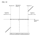
- FIG. 30 is a diagram illustrating a relationship between an edge amount input (X axis) and an edge amount output (Y axis) in sharpening processing which is described in a first embodiment of Patent Document 1 below.
- the unsharp mask (USM) of a sharpening processing algorithm will be described with reference to FIG. 1A and FIG. 30 .
- a difference (edge amount input) between an input video signal (RGB or YUV) and an input image signal around the input video signal (spacial filter output) is obtained.
- the spacial filter output is data obtained by smoothing the input video signal.
- the smoothing is regarded as a synonym for noise elimination.
- the sharpening for enhancing the sharpness is performed by multiplying an edge amount by use of parameters and adding the result to target pixel data, the parameters being defined as a threshold (Th) set on the X axis and a gain ( ⁇ ) indicating the strength of the sharpening.
- Th threshold
- ⁇ gain
- FIG. 30 when an absolute value of the edge amount input is smaller than the threshold Th, the edge amount input is regarded as a noise and no sharpening is performed. This is because it is favorable in terms of image quality not to perform sharpening.
- a range in which the input is regarded as a noise can be specified by the threshold.
- the gain is a parameter used to convert the edge amount input.
- the strength of sharpening is adjustable by increasing or decreasing the gain. Note that the processing image by the USM will be described by using FIG. 1C later.
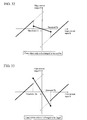
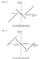
- FIG. 31 is a diagram illustrating an overview of a technique for smoothing and sharpening which is described in a fourth embodiment of Patent Document 1.
- ⁇ is a parameter indicating the strength of smoothing
- ⁇ is a parameter indicating the strength of sharpening
- ⁇ is a parameter of an intersection with an edge amount output (Y) axis
- a threshold parameter Th is a value of the edge amount input at which switching is made between a smoothing conversion and a sharpening conversion.
- Patent Document 1 requires settings of four parameters of the threshold Th, ⁇ , ⁇ , and ⁇ (see FIG. 31 and Formula 2 above). Moreover, it is not allowed to adjust only one of the four parameters in order that X-Y input-output conversions keep continuity in input-output characteristics across the threshold Th. Furthermore, Patent Document 1 lacks a description of a behavior at the enlargement or reduction of an image, and thus it is unclear as to how the four parameters should be set, or the like. For example, Patent Document 1 does not disclose how parameters should be set to achieve high quality image and to keep the continuity in a case where an enlarged image is to be converted by both smoothing processing and sharpening processing.
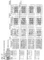
- FIG. 32 to FIG. 39 are diagrams of examples of edge amount input-output characteristics obtained by adjusting only a single one of the parameters ⁇ , ⁇ , ⁇ , and Th with respect to basic conversion characteristics illustrated in FIG. 31 of the above-mentioned fourth embodiment of Patent Document 1, where the parameters ⁇ , ⁇ , ⁇ , and Th are used as bases and each of the parameters ⁇ , ⁇ , ⁇ , and Th is independently changed slightly or largely.
- FIG. 32 is a diagram illustrating an example in a case where only ⁇ is changed to be smaller than the one illustrated in FIG. 31 .
- Patent Document 1 requires the use of the four parameters and involves a problem that an adjustment of one of the parameters spoils the keeping of the continuity of the smoothing input-output characteristic and the sharpening input-output characteristic around the threshold.
- the present invention aims to reduce the number of parameters to be used and to keep continuity of the smoothing input-output characteristic and the sharpening input-output characteristic even after adjusting one of the parameters.
- the present invention also aims to enhance freedom in a parameter adjustment.
- One aspect of the present invention provides a video signal circuit which performs smoothing processing and sharpening processing on an input video signal to obtain an output video signal
- the video signal processing circuit characterized in that when an edge amount input (X) of the input video signal is to be converted to an edge amount output (Y), input-output characteristics of a video signal are determined by providing a first function (Function 1) and a second function (Function 2) and by setting at least one of three factors as a variable parameter, where in a positive range of X of an X-Y plane defined by the edge amount input X and the edge amount output Y, the first function passes an origin and performs smoothing processing on condition that 0 ⁇ X ⁇ Th1 and the second function passes a point (Th1, 0) on an X axis at which the threshold is set to a value of X and performs smoothing processing on condition that 0 ⁇ X ⁇ Th1 and performs sharpening processing on condition that X>Th1, and the three factors are a smoothing coefficient ( ⁇ 1) for determining the
- a video signal circuit which performs smoothing processing and sharpening processing on an input video signal to obtain an output video signal
- the video signal processing circuit characterized in that when an edge amount input (X) of the input video signal is to be converted to an edge amount output (Y), input-output characteristics of a video signal are determined by providing a first function (Function 1) and a second function (Function 2) and by setting at least one of three factors as a variable parameter, where in a negative range of X of an X-Y plane defined by the edge amount input X and the edge amount output Y, the first function passes an origin and performs smoothing processing on condition that Th2 ⁇ X ⁇ 0 and the second function passes a point (Th2, 0) on an X axis at which the threshold is set to a value of X and performs smoothing processing on condition that Th2 ⁇ X ⁇ 0 and performs sharpening processing on condition that X ⁇ Th2, and the three factors are a smoothing coefficient ( ⁇ 2) for determining the strength of the smoothing processing,
- the smoothing coefficients ( ⁇ 1, ⁇ 2) are coefficients for the first function (Function 1) while the sharpening coefficients ( ⁇ 1, ⁇ 2) are coefficients for the second function (Function 2).
- a coefficient denotes an inclination in a case where, for example, Function 1 or 2 described above is a straight line, while it denotes a magnification by which a variable or a constant value is multiplied in a case where Function 1 or 2 is a curve.
- the present invention may be a display device characterized by including a display unit which performs a display in accordance with the output video signal of the video signal processing circuit described above.
- the present invention may also be a mobile terminal device characterized by including the display device.
- the present invention it is possible to obtain a smooth high-quality video image since switching between data to be sharpened and data to be smoothed is always continuous in X-Y input-output characteristics related to an edge amount input X and an edge amount output Y, the edge amount input X being a difference between an input video signal and an output signal obtained by processing the input video signal by use of a spacial filter, the edge amount output Y being obtained by converting the edge amount input X.
- first arithmetic circuit for computing Equation 2-2 54... second arithmetic circuit for computing Equation 2-1, 55... third arithmetic circuit for computing Equation 2-4, 71... register, 72... circuit for determining a threshold in Equation 3-3, 73... first arithmetic circuit for computing Equation 3-2, 74... second arithmetic circuit for computing Equation 3-1, 75... third arithmetic circuit for computing Equation 3-4, 81... register, 83... circuit for determining Equation 4-3, 85... first arithmetic circuit for computing Equation 4-2, 87... second arithmetic circuit for computing Equation 4-1, 89... third arithmetic circuit for computing Equation 4-4, 91... register, 93...
- circuit for determining Equation 5-3 95... first arithmetic circuit for computing Equation 5-2, 97... second arithmetic circuit for computing Equation 5-1, 99... third arithmetic circuit for computing Equation 5-4, 101... input video signal, 103... line memory, 105... memory controller, 107... spacial filter, 111... delay circuit, 113... subtraction circuit, 115... edge amount input, 121... display device, 123... external connection terminal, 125... controlling unit, 127... external memory interface I/F, 131... video signal processing unit, 131a... sharpening smoothing processing unit, 131b... ⁇ correction unit, 133... display unit, 141... mobile terminal device, 143... operation unit, 145... radio communication unit, 147...
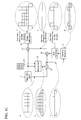
- FIG. 1A is a functional block diagram illustrating an overview of a sharpening processing (unsharp mask (USM)) algorithm.
- a sharpening processing unit A calculates a difference (edge amount input) (reference symbol B) between an input video signal (RGB or YUV) and an input image signal around the input video signal (spacial filter output).
- the spacial filter output is data obtained by smoothing the input video signal.
- the sharpening for enhancing the sharpness is performed by multiplying an edge amount by use of parameters and adding the result to target pixel data, the parameters being defined as a threshold (Th) set on the X axis and a gain ( ⁇ ) indicating the strength of the sharpening.
- Th threshold
- ⁇ gain
- the edge amount input is regarded as a noise and no sharpening is performed on the signal. This is because it is favorable in terms of image quality not to perform sharpening.
- a range in which the input is regarded as a noise can be specified by the threshold.
- a gain used for the gain adjustment is a parameter for converting the edge amount input.
- the strength of sharpening is adjusted by increasing or decreasing the gain to obtain an output video signal Y. In this manner, the input video signal is converted into the output video signal.
- FIG. 1B is a functional block diagram illustrating a configuration example of peripheral circuits of the spacial filter, which is the detail for the configuration denoted by the reference symbol B in FIG. 1A .
- input video signals 101 are accumulated in line memories 103 (first to third line memories 103a to 103c) which are controlled by a memory controller 105, and then outputted to a spacial filter 107 in order.
- Video signals subjected to filtering by the spacial filter 107 are outputted to a subtraction circuit 113.
- the outputs from the line memories 103 are also outputted to a delay circuit 111, and are then outputted to the subtraction circuit 113 with a certain delay.
- the subtraction circuit 113 performs subtraction operation on both the input signals and thus outputs the result as an edge amount input 115.
- FIG. 1C Each of diagrams drawn out of signal lines and denoted by reference symbols a to f is a schematic diagram, of pixel values of a point of an image when the pixel value is seen from the side, in which the pixel values are expressed in a vertical height direction.
- an input video signal 1 is illustrated by an image denoted by the reference symbol a. If the input video signal 1 is filtered by a spacial filter 3 of 3 ⁇ 3, for example, the input video signal 1 is smoothed as denoted by the reference symbol b. Next, a subtracter 5 subtracts b from a, and thus a difference is obtained as denoted by the reference symbol c.
- a threshold judgment unit 7 makes a judgment as denoted by the reference symbol d.
- a gain adjustment unit 11 performs a gain adjustment on the signal if the signal represents the difference not less than a threshold. On the other hand, if the signal represents the difference less than the threshold, the signal vanishes (reference symbol e).
- An adder 17 adds an input signal a to the signal representing the difference not less than the threshold to thereby obtain an output video signal Y 21, i.e., a signal which is subjected to sharpening and denoted by the reference symbol f.
- a smoothing parameter ⁇ is defined to be smaller as it is closer to 0; a sharpening parameter ⁇ is defined to be smaller as it is closer to 0; and a threshold parameter Th is defined to be smaller as it is closer to 0.
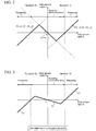
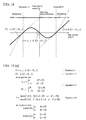
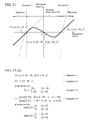
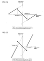
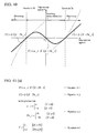
- FIG. 2 is a diagram illustrating the principle of the video signal adjustment technique according to this embodiment, and is also a diagram for performing an X-Y conversion.
- FIG. 2 also shows equations for the X-Y conversion.
- a range between -Th and +Th is set as one in which smoothing (noise elimination) processing is performed, while a range outside of the above range is set as one in which sharpening processing is performed.
- intersections of the equation Y1 and the equation Y2 are the maximum value and the minimum value of the X-Y conversion equations, where the equation Y1 is on the inner side on the X axis while the equation Y2 is on the outer side on the X axis.
- parameters to be used are set to be formed by only three factors, i.e., a parameter ⁇ indicating the strength of smoothing, a parameter ⁇ indicating the strength of sharpening, and a threshold Th on the X axis which defines switching between the smoothing processing and the sharpening processing.
- the inclinations of the functions can be changed according to the values of ⁇ and ⁇ while an intersection with the X axis and the function can be determined by Th.
- FIG. 3 to FIG. 8 are diagrams each illustrating an example of the input-output characteristics (Y1, Y2) observed when any one of the three parameters ⁇ , ⁇ , and Th shown in FIG. 2 is independently made smaller or larger.
- FIG. 3 is an example where only ⁇ is changed to be smaller.
- Y1 is less inclined, it is possible to keep the continuity of the X-Y conversion equations because Y2 does not depend on ⁇ and the maximum value and the minimum value of Y are determined as intersections of Y1 and Y2.
- FIG. 4 is an example where only ⁇ is changed to be larger.
- Y1 is more inclined, it is possible to keep the continuity of the X-Y conversion equations because Y2 does not depend on ⁇ and the maximum value and the minimum value of Y are determined as intersections of Y1 and Y2.
- FIG. 5 is an example where only ⁇ is changed to be smaller.
- Y2 is less inclined, it is possible to keep the continuity of the X-Y conversion equations because Y1 does not depend on ⁇ and the maximum value and the minimum value of Y are determined as intersections of Y1 and Y2.
- FIG. 6 is an example where only ⁇ is changed to be larger.
- FIG. 7 is an example where only Th is changed to be smaller.
- it is possible to keep the continuity of the X-Y conversion equations because the inclinations of Y1 and Y2 have no change and the maximum value and the minimum value of Y are determined as intersections of Y1 and Y2. The same applies to the case where only the Th is changed to be larger as shown in FIG. 8 .
- this embodiment by setting the intersections of the sharpening characteristic data and the smoothing characteristic data to be on the inner side of the threshold Th, it is possible to change the sharpening parameter and the smoothing parameter independently of the threshold Th and to always keep continuity between sharpening characteristic data and smoothing characteristic data. Accordingly, this embodiment enables obtaining a smooth high-quality video image. Moreover, this embodiment enables obtaining a different output video signal depending on any of the three parameters. [Table 1] Parameters Reduced to half Normal condition Enlarged to double ⁇ -1 -1 0 ⁇ 1 2 4 Th 6 4 2
- Table 1 shows an example of parameter settings in the video signal adjustment technique according to this embodiment.
- Table 1 also shows ⁇ , ⁇ , and Th in cases where an image is reduced to half size and is enlarged to double size.
- the display device is a color TFT liquid crystal panel with a size of 24.1 ", a pixel pitch of 0.27 x 0.27 mm, and a recommended resolution of 1920 ⁇ 1200.
- the filter setting the filter size is 5 ⁇ 5 and all the filter coefficients are "1.”
- a displayed image has an image type of a static image and the image size of 480x640. Processing was performed on a Y (luminance) component in YUV.
- FIG. 9(b) is a functional block diagram illustrating an example of a video signal conversion circuit according to this embodiment.
- FIG. 9(a) is a diagram showing arithmetic equations used in the functional blocks.
- a video signal conversion circuit C1 shown in FIG. 9(b) includes: a register 31 which stores the values of the threshold Th, ⁇ , and ⁇ ; a circuit 32 for determining the threshold in Equation 1-3; a first arithmetic circuit 33 for computing Equation 1-2; a second arithmetic circuit 34 for computing Equation 1-1; and a third arithmetic circuit 35 for computing Equation 1-4.
- the third arithmetic circuit 35 includes: a circuit 36 for calculating the maximum value for Y1 and Y2; a circuit 37 for calculating the minimum value for Y1 and Y2; and a circuit 38 for calculating Y on the basis of the outputs and thus outputting Y.
- An input signal X is inputted into the circuits 32, 33, 34, and 38.
- Y is outputted from the circuit C1. This configuration enables achievement in a high-quality display based on a video signal while keeping the circuit size small.
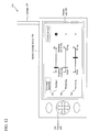
- FIG. 10 is a diagram illustrating a configuration example of a display device 121 which includes a video signal processing circuit (sharpening smoothing processing unit 131a) according to this embodiment.
- the display device 121 includes an external connection terminal 123, a controlling unit 125, an external memory interface I/F 127, a video signal processing unit 131, and a display unit 133.
- An input video signal is received by the external connection terminal 123 or the external memory interface I/F 127.
- ⁇ correction is made by the video signal processing unit 131 and the signal processing is performed by the aforementioned sharpening smoothing processing unit 131a.
- the output video signal processed in this manner can be outputted to the display unit 133, so that a video image can be displayed.
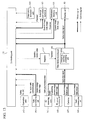
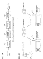
- FIG. 11 is a functional block diagram illustrating a configuration example of a mobile terminal device 141 employing the sharpening smoothing circuit according to this embodiment.
- the mobile terminal device 141 includes: an operation unit 143; a radio communication unit 145; a camera 147; a dedicated memory unit 151; a RAM/ROM 153; an orientation detection unit 155 which detects the orientation of a foldable type mobile terminal device, for example; a register 157; a TV receiving unit 161; an external connection terminal 163; an external memory I/F 165; a power supply (battery) 167; controlling unit (CPU)171; a video signal processing unit 181 which outputs an output video signal; and a display unit 183 which displays a video image according to the outputted video signal.
- an operation unit 143 includes: an operation unit 143; a radio communication unit 145; a camera 147; a dedicated memory unit 151; a RAM/ROM 153; an orientation detection unit 155 which detects the orientation of a
- the video signal processing unit 181 includes: an RGBYUV conversion unit 181a; a sharpening smoothing processing unit 181b; a YUVRGB conversion unit 181c; and a ⁇ correction unit 181d.
- FIG. 12 is a diagram illustrating an example where a user interface which allows changing adjustment parameters in the sharpening smoothing processing unit is displayed on the display unit 183 of the mobile terminal device shown in FIG. 11 .
- a mobile terminal device 191 is provided with a display unit 183, an operation unit 143, and an antenna 197.
- Set values of three parameters Th (threshold) 192, ⁇ (sharpening) 193, and ⁇ (smoothing) 194 displayed on the display unit 183 can be changed by use of the operation unit 143 (the figure illustrates a situation where the threshold 192 is being adjusted).
- the parameters may be adjusted by a manufacturer of the mobile terminal device at the time of the shipment in order to eliminate individual differences, or may be adjusted by a user according to his/her taste.
- a preferable configuration is one which allows the user to check a video image while the adjustment parameters are being changed.
- a menu display can be displayed on the display unit 183 in a superimposed manner while the video image after the adjustment can be checked in a full-screen display.
- a display unit for a setting purpose may be separately provided.
- FIG. 13 is a diagram illustrating an example of a scene where the video image processing technique according to this embodiment is used.
- the controlling unit (CPU) 171 performs overall control. Parameters can be set by the user on the operation unit 143. In addition, the parameters can be set from the radio communication unit 145 via a radio communication. It is also possible to control the mobile terminal device according to a detection result from the orientation detection unit 155. For example, the orientation detection unit 155 is capable of detecting whether the display unit of the mobile terminal device provides a portrait display or a landscape display. In addition, parameters can also be set according to broadcast data from the television (TV) receiving unit 161, as will be described later.
- TV television
- An input video signal is obtained from a source such as a dynamic or static image supplied from the radio communication unit 145, the camera 147, and the external memory I/F and a video image of digital broadcasting supplied from the TV receiving unit 161.
- the sharpening smoothing processing unit 181b of the video signal processing unit 181 performs the sharpening smoothing processing according to this embodiment.
- the parameters used for this processing are set from the setting units described above, so that the set values which are set in the register 157 via the controlling unit 171 can be updated.
- the sharpening processing/smoothing processing are performed on the input video image by use of the updated parameters.
- the output video signal is outputted to the display unit 183, so that the video image can be displayed thereon.
- an output video signal can be transmitted to the controlling unit 171, and then this output video signal (dynamic image/static image) can be outputted to the radio communication unit 145, the external connection terminal 163, or the dedicated memory unit 151, such as a hard disk or a memory card.
- the parameter values based on the settings can also be outputted to the radio communication unit 145, the external connection terminal 163, or the dedicated memory unit 151.
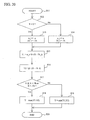
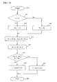
- FIG. 14 is a diagram illustrating a processing flow in the video signal processing unit.
- an input video signal is inputted into the RGBYUV conversion unit 181a; the sharpening smoothing processing unit 181b then performs conversion processing according to this embodiment on the signal; the YUVRGB conversion unit 181c then performs conversion on the signal; the gamma correction unit 181d then performs a gamma correction on the signal; and thus an output video signal is outputted.
- FIG. 15 is a diagram illustrating an example of an application scene where set values are transmitted or received.
- set values on a mobile terminal device 191a used by a user A may be directly transmitted via a network 203 to a mobile terminal device 191b used by a user B.
- the set values includes: set values which are transmitted as parameters according to transmission of an image on a TV phone; set values which are obtained by a user's adjustment in a way the set values match the television (TV) broadcasting which is broadcast by a radio wave tower 201 and which the user is viewing; and other values.
- TV television
- set values may be assigned to a content (program) itself of the television broadcasting.
- a video content which is assigned set values may be made downloadable via a server 205.
- the set values which match a dynamic image content should be obtained together with the content, so that adjustment values which match the video content can be set in the register.
- obtaining set values of the parameters which match the contents together with the contents makes it possible to perform sharpening smoothing processing by use of the parameters suitable to the contents.
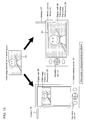
- FIG. 16 is a diagram illustrating an example of a display related to enlargement/reduction of a displayed video image.
- the reference symbol 197 denotes an antenna for TV reception.
- the video image can be displayed on the basis of such a setting. Even when there is no such setting, the video image can be easily adjusted according to user's taste as long as the user I/F as described above is prepared.
- a video image received by a television of the mobile terminal device 191 is denoted by D1.
- the TV video image needs to be reduced in size, as in a case shown in D2 where the TV video image is to be displayed in a portrait screen mode, on the display unit 183 of the mobile terminal device 191 and where the video display area D2 has the smaller resolution than the received video image D1 does.
- the TV video image needs to be enlarged in size, as in a case shown in D3 where the TV video image is to be displayed in a landscape screen mode and where a video display area D3 has the larger resolution than the received video image D1 does.
- the display quality can be improved by decreasing the ratio of data to be smoothed and increasing the ratio of data to be sharpened.
- an eye-friendly display which is not so strong can be obtained with such an adjustment that the ratio of data to be smoothed is increased and the ratio of data to be sharpened is decreased.
- the operation includes not only a simple key operation on the operation unit 143 by the user but also the changing of the orientation of a casing (for example, a rotational operation of the display unit, and the like), and also includes an automatic operation by detecting the orientation at the time.
- the orientation detection unit 155 shown in FIG. 13 or the like can detect the orientation.
- a controlling unit judges, by use of the orientation detection unit, whether the display is on the portrait screen display mode or the landscape screen display mode, and updates the set values in the register as needed.
- Step S10 the sharpening smoothing processing as shown in FIG. 2 can be performed by software processing.
- this embodiment makes the sharpening smoothing processing easy by setting a coefficient of the first function as the smoothing parameter ( ⁇ ) and by setting a coefficient of the second function as the sharpening parameter ( ⁇ ), the first function being defined as a function passing the origin, the second function being defined as a function passing the threshold Th.
- FIG. 18 is a diagram illustrating the principle of the video image processing technique according to this embodiment and is a drawing for X-Y conversion.
- FIG. 19 is a functional block diagram illustrating an example of a video signal conversion circuit according to this embodiment.
- FIG. 19(a) shows arithmetic equations used in the functional blocks.
- a video signal conversion circuit C2 shown in FIG. 19(b) includes: a register 51 which stores the values of the threshold Th, ⁇ , and ⁇ ; a circuit 52 for determining the threshold and ⁇ in Equation 2-3; a first arithmetic circuit 53 for computing Equation 2-2; a second arithmetic circuit 54 for computing Equation 2-1; and a third arithmetic circuit 55 for computing Equation 2-4.
- the third arithmetic circuit 55 includes: a circuit 56 for calculating the maximum value for Y1 and Y2; a circuit 57 for calculating the minimum value for Y1 and Y2; and a circuit 58 for calculating Y on the basis of the outputs and thus outputting Y.
- An input signal X is inputted into the circuits 52, 53, 54, and 58.
- Y is outputted from the circuit C2. This configuration enables achievement in a higher-quality display based on a video signal while keeping the circuit size small.
- this embodiment makes the sharpening smoothing processing easy by setting as the smoothing parameter ( ⁇ ) a coefficient of a quadratic curve which is a first function and by setting as the sharpening parameter ( ⁇ ) the inclination of a straight line which is a second function, the first function being defined as a function passing the origin, the second function being defined as a function passing the threshold Th.
- FIG. 21 is a drawing illustrating the principle of the video image processing technique according to this embodiment and is a drawing for X-Y conversion.
- Y1 ⁇ X ⁇ (X-Th_t) ⁇ (X+Th_t) passing the origin and thresholds Th and -Th
- FIG. 22 is a functional block diagram illustrating an example of a video signal conversion circuit according to this embodiment.
- FIG. 22(a) shows arithmetic equations used in the functional blocks.
- a video signal conversion circuit C3 shown in FIG. 22(b) includes: a register 71 which stores the values of the threshold Th, ⁇ , and ⁇ ; a circuit 72 for calculating the threshold Th_t by Equation 3-3; a first arithmetic circuit 73 for calculating ⁇ (X-Th_t) by Equation 3-2; a second arithmetic circuit 74 for calculating ⁇ X ⁇ (X-Th_t) ⁇ (X+Th_t) by Equation 3-1; and a third arithmetic circuit 75 for calculating Y based on Equation 3-4.
- the third arithmetic circuit 75 includes: a circuit 76 for calculating the maximum value for Y1 and Y2; a circuit 77 for calculating the minimum value for Y1 and Y2; and a circuit 78 for calculating Y on the basis of the outputs and thus outputting Y.
- An input signal X is inputted into the circuits 72, 73, 74, and 78.
- Y is outputted from the circuit C3. This configuration enables achievement in a higher-quality display based on a video signal while keeping the circuit size small.
- Step S40 the sharpening smoothing processing can be performed by the software processing.
- this embodiment makes the sharpening smoothing processing easy by setting as the smoothing parameter ( ⁇ ) a coefficient of a cubic curve which is a first function and by setting as the sharpening parameter ( ⁇ ) the inclination of a straight line which is a second function, the first function being defined as a function passing the origin, the second function being defined as a function passing the threshold Th.
- n-th degree (n is an integer of 4 or greater) curve may be used.
- the straight line, the quadratic curve, and the like do not have to be an exact curve, and the intersections with the X axis and the like do not have to exactly match the origin or the threshold.
- Equations as shown in FIG. 41 (a) may be used for the arithmetic equations in this case.
- the input-output characteristics are expressed as shown in FIG. 40 .
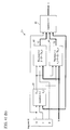
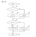
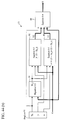
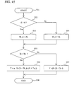
- FIG. 41 (b) is a functional block diagram illustrating an example of a video signal conversion circuit and FIG. 42 is a flowchart illustrating a processing flow for performing processing by software processing. Further, for example, if it is desired to make the arithmetic circuit denoted by 75 in FIG. 22(b) simpler, for example, this can be similarly made possible as long as the switching between the smoothing processing and the sharpening processing is surely made at the threshold. Equations as shown in FIG. 44(a) may be used for the arithmetic equations in this case. Here, the input-output characteristics are expressed as shown in FIG. 43 .
- FIG. 44(b) is a functional block diagram illustrating an example of a video signal conversion circuit and FIG.
- the threshold parameter does not have to be a parameter but may be a fixed value.
- the circuit size can be made further smaller. That is, it is only necessary that at least one of the three parameters is variable.
- the description is given by taking, as an example, the case where the filter size is 3 ⁇ 3 and all the filter coefficients are 1. However, the filter size may be set to 5 ⁇ 5, or 7 ⁇ 7, or the filter coefficients may be set to be different from one another.
- the description is given also by taking, as an example, the case where processing is performed on a Y (luminance) component in YUV data. However, the processing can be performed in the same manner on data such as Y of YCbCr, YPbPr, and YIQ, L of L*u*v* and L*a*b*, and RGB.
- FIG. 24 is a schematic diagram illustrating ranges on the X axis based on the first embodiment of the present invention (Part a) and on the video image processing technique according to the first embodiment of Patent Document 1 (Part b).
- the threshold Th is used as a border to divide the range into an area where sharpening is performed and an area where sharpening is not performed.
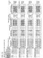
- FIG. 25 is a diagram in which smoothing processing results are compared between the video image processing technique according to this embodiment and the conventional technique, by illustrating examples.
- FIG. 1 In order from the left, illustrated are diagrams illustrating examples of: input video signals (luminance) in 5 ⁇ 5; edge amount inputs (rounded-off value); output video signals according to the conventional technique; and output video signals according to this embodiment.
- a Standard deviation of luminance in each plane is shown on the right side. It is found that since some of data pieces were smoothed, the standard deviations were smaller and the images were smoother and had a higher quality than those according to the conventional technique. Moreover, even in the case where the sharpening parameter was doubled, the standard deviation had no change from the normal condition as in the case where the sharpening parameter was not doubled since there was no sharpening data piece. For this reason, the image was smoother and had a higher quality than those according to the conventional technique.
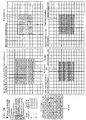
- FIG. 26 is a diagram in which smoothing processing results are compared between the case of FIG. 25 and a case where the display is enlarged in size to be doubled, by illustrating examples. It is found that the edge amount input characteristically became smaller than that in the normal condition, i.e., than that before the enlargement. It is found that since all the data pieces were smoothed in this embodiment, the standard deviation was smaller and the image was smoother and had a higher quality than those of the conventional technique. In this case, the edge amount input became smaller than that before the enlargement, and all the pixels were smoothed in this example.
- FIG. 27 is a diagram in which sharpening processing results are compared between the video image processing technique according to this embodiment and the conventional technique, by illustrating examples, and is a drawing equivalent to FIG. 25 .
- this embodiment there are data pieces to be smoothed and data pieces to be sharpened.
- the switching between the sharpening processing and the smoothing processing is made continuously. For this reason, it is found that this embodiment provides an image which is smoother and of higher quality than that according to the conventional technique.
- FIG. 28 is a diagram in which smoothing processing results are compared between the case of FIG. 27 and a case where the display is enlarged in size to be doubled, by illustrating examples.
- the same setting as that of the normal condition adversely leads to smoothing all the output results of this embodiment.
- the use of the same parameters as those of the normal condition leads to a result where a quite a large number of pixels are smoothed at the enlargement since the edge amount input becomes smaller than that before the enlargement.
- an image has a higher quality by reducing the ratio of data to be smoothed and by increasing the ratio of data to be sharpened.
- at least one of the following three operations is performed, and thereby a higher-quality image can be obtained.
- the three operations are: making the threshold Th smaller; making the parameter ⁇ to determine the smoothing amount smaller; and making the parameter ⁇ to indicate the sharpening amount larger.
- an image can be adjusted according to the user's taste even though he/she has not checked what the enlargement algorithm in the previous step is like since the three parameters can be adjusted after seeing the output result.
- FIG. 29 is a diagram illustrating a result obtained after data of an image which was once enlarged in size in FIG. 28 and then reduced in size to be half was subjected to the smoothing and the sharpening processing, as an input video signal.
- the set values obtained by performing at least one of the following three operations at the reduction are set as the set values for the reduction and thereby a higher-quality image can be obtained.
- the three operations are: making the threshold Th larger; making the parameter ⁇ to determine the smoothing amount larger; and making the parameter ⁇ to indicate the sharpening amount smaller.
- the edge amount input X being a difference between an input video signal and an output signal obtained by processing the input video signal by use of a spacial filter
- the edge amount output Y being obtained by converting the edge amount input X.
- a different output video signal can be obtained depending on any of the three parameters, a high-quality video image can be obtained even when the image is enlarged or reduced in size (e.g., portrait display or landscape display in TV broadcasting).
- a second function which passes a point on the X axis where the threshold is set to an X value (Th1, 0) and performs smoothing processing on condition that 0 ⁇ X ⁇ Th1 as well as which performs sharpening processing on condition that X>Th1, as far as the second function passes near the point (Th1, 0)
- the second function is regarded as being within the scope of the present invention even though the second function does not pass the point.
- the present invention is a video signal circuit which performs smoothing processing and sharpening processing on an input video signal to obtain an output video signal.
- the video signal circuit according to the present invention is characterized in that when an edge amount input (X) of the input video signal is to be converted to an edge amount output (Y), input-output characteristics of the video signal are determined by continuous functions each of which includes three factors and in each of which at least one of the three factors is set as a variable parameter, the three factors being a smoothing coefficient ( ⁇ ) for determining the strength of the smoothing processing, a sharpening coefficient ( ⁇ ) for determining the strength of the sharpening processing, and a threshold (Th) for determining a point (X) at which switching is made between the smoothing processing and the sharpening processing.
- the present invention can be modified, replaced, or subjected to other changes in various ways within a scope conceivable by those skilled in the art. Even in such a case, the modification, the replacement, and the like are regarded to be within the scope of the present invention.
- processing may be performed on each component by recording a program for achieving the functions described in the embodiments in a computer readable recording medium and by causing a computer system to read and execute the program recorded in the recording medium.
- the "computer system” here includes hardware such as an OS and peripheral devices.
- the "computer system” includes a homepage providing environment (or display environment) provided that a WWW system is used.
- the "computer readable recording medium” denotes: a transportable medium such as a flexible disk, a magneto-optical disk, a ROM and a CD-ROM; or a storage device such as a hard disk incorporated in the computer system.
- the "computer readable recording medium” includes: a component which dynamically holds a program for a short time period like a communication line used in a case of transmitting a program via a network such as the Internet or a communication line such as a telephone line; and a component which dynamically holds the program for a certain time period, like a volatile memory inside the computer system serving as a server or a client in the aforementioned case.
- the program may be the one for implementing a part of the functions described above or may be the one which is capable of implementing the above functions in combination with another program which has been recorded in the computer system in advance.
- the present invention is applicable to a video image processing circuit.
Landscapes
- Engineering & Computer Science (AREA)
- Physics & Mathematics (AREA)
- General Physics & Mathematics (AREA)
- Theoretical Computer Science (AREA)
- Multimedia (AREA)
- Signal Processing (AREA)
- Image Processing (AREA)
- Picture Signal Circuits (AREA)
Applications Claiming Priority (2)
| Application Number | Priority Date | Filing Date | Title |
|---|---|---|---|
| JP2008182724 | 2008-07-14 | ||
| PCT/JP2009/062512 WO2010007933A1 (fr) | 2008-07-14 | 2009-07-09 | Dispositif de traitement de signal d'image et dispositif d'affichage d'image |
Publications (2)
| Publication Number | Publication Date |
|---|---|
| EP2315431A1 true EP2315431A1 (fr) | 2011-04-27 |
| EP2315431A4 EP2315431A4 (fr) | 2012-06-27 |
Family
ID=41550336
Family Applications (1)
| Application Number | Title | Priority Date | Filing Date |
|---|---|---|---|
| EP09797858A Ceased EP2315431A4 (fr) | 2008-07-14 | 2009-07-09 | Dispositif de traitement de signal d'image et dispositif d'affichage d'image |
Country Status (5)
| Country | Link |
|---|---|
| US (1) | US8351734B2 (fr) |
| EP (1) | EP2315431A4 (fr) |
| JP (1) | JP5279830B2 (fr) |
| CN (1) | CN102100060A (fr) |
| WO (1) | WO2010007933A1 (fr) |
Families Citing this family (5)
| Publication number | Priority date | Publication date | Assignee | Title |
|---|---|---|---|---|
| JP2011035776A (ja) * | 2009-08-04 | 2011-02-17 | Sanyo Electric Co Ltd | 映像情報処理装置およびプログラム |
| US20140241589A1 (en) * | 2011-06-17 | 2014-08-28 | Daniel Weber | Method and apparatus for the detection of visibility impairment of a pane |
| JP5932374B2 (ja) * | 2012-02-02 | 2016-06-08 | キヤノン株式会社 | 画像処理装置及び画像処理方法 |
| WO2016022374A1 (fr) * | 2014-08-05 | 2016-02-11 | Seek Thermal, Inc. | Réglage de contraste local pour des images numériques |
| CN106297725B (zh) * | 2016-08-26 | 2019-03-19 | 南京巨鲨显示科技有限公司 | 具有一键图像锐化及平滑功能的灰阶显示器及其调节方法 |
Family Cites Families (15)
| Publication number | Priority date | Publication date | Assignee | Title |
|---|---|---|---|---|
| JPH03245675A (ja) * | 1990-02-23 | 1991-11-01 | Matsushita Electric Ind Co Ltd | 画像処理装置 |
| KR0170657B1 (ko) * | 1994-08-31 | 1999-03-30 | 김광호 | 색신호에 있는 윤곽을 보정하는 방법 및 이를 칼라 비디오기기에서 구현하기 위한 회로 |
| KR0160718B1 (ko) * | 1995-08-29 | 1999-01-15 | 김광호 | 색신호에 포함된 윤곽을 보정하는 방법 및 이를 칼라 비디오기기에서 구현하기 위한 회로 |
| US6246783B1 (en) * | 1997-09-17 | 2001-06-12 | General Electric Company | Iterative filter framework for medical images |
| US7265873B1 (en) * | 1999-04-13 | 2007-09-04 | Conexant Systems, Inc. | Image processor that performs edge enhancement using a dynamic threshold |
| WO2002025589A1 (fr) * | 2000-09-20 | 2002-03-28 | Nik Multimedia, Inc. | Systeme d'affinage d'images numeriques |
| JP4443784B2 (ja) * | 2000-12-07 | 2010-03-31 | 株式会社エヌ・ティ・ティ・ドコモ | 画像符号化・復号方法、画像符号化装置及び画像復号装置 |
| US7206459B2 (en) * | 2001-07-31 | 2007-04-17 | Ricoh Co., Ltd. | Enhancement of compressed images |
| US7545976B2 (en) * | 2002-05-01 | 2009-06-09 | Hewlett-Packard Development Company, L.P. | Method and apparatus for associating image enhancement with color |
| US7570832B2 (en) * | 2004-06-14 | 2009-08-04 | Precoad Inc. | Image clean-up and pre-coding |
| TWI280046B (en) * | 2005-09-20 | 2007-04-21 | Novatek Microelectronics Corp | Device and method for sharpening image signal |
| US8442344B2 (en) * | 2006-08-07 | 2013-05-14 | Qualcomm Incorporated | Adaptive spatial image filter for filtering image information |
| JP4771902B2 (ja) * | 2006-09-19 | 2011-09-14 | 株式会社リコー | 画像処理装置及び画像処理方法 |
| JP2008113337A (ja) * | 2006-10-31 | 2008-05-15 | Konica Minolta Holdings Inc | 撮像装置 |
| US8335403B2 (en) * | 2006-11-27 | 2012-12-18 | Nec Laboratories America, Inc. | Soft edge smoothness prior and application on alpha channel super resolution |
-
2009
- 2009-07-09 US US13/054,003 patent/US8351734B2/en not_active Expired - Fee Related
- 2009-07-09 CN CN2009801274449A patent/CN102100060A/zh active Pending
- 2009-07-09 JP JP2010520841A patent/JP5279830B2/ja not_active Expired - Fee Related
- 2009-07-09 WO PCT/JP2009/062512 patent/WO2010007933A1/fr not_active Ceased
- 2009-07-09 EP EP09797858A patent/EP2315431A4/fr not_active Ceased
Also Published As
| Publication number | Publication date |
|---|---|
| WO2010007933A1 (fr) | 2010-01-21 |
| EP2315431A4 (fr) | 2012-06-27 |
| CN102100060A (zh) | 2011-06-15 |
| US20110115982A1 (en) | 2011-05-19 |
| JPWO2010007933A1 (ja) | 2012-01-05 |
| US8351734B2 (en) | 2013-01-08 |
| JP5279830B2 (ja) | 2013-09-04 |
Similar Documents
| Publication | Publication Date | Title |
|---|---|---|
| CN102438097B (zh) | 图像处理装置与图像处理方法 | |
| US8401324B2 (en) | Visual processing apparatus, visual processing method, program, recording medium, display device, and integrated circuit | |
| US9189831B2 (en) | Image processing method and apparatus using local brightness gain to enhance image quality | |
| US8374430B2 (en) | Apparatus and method for feature-based dynamic contrast enhancement | |
| US20090009665A1 (en) | Image processing apparatus, image processing method and program | |
| KR20090068355A (ko) | 윤곽보정방법, 화상처리장치 및 표시장치 | |
| US7430021B2 (en) | Video display apparatus having contour correction function | |
| US6600518B1 (en) | Adaptive clipping prevention for picture sharpness enhancement | |
| JP2001157085A (ja) | 輪郭補正装置 | |
| EP2315431A1 (fr) | Dispositif de traitement de signal d'image et dispositif d'affichage d'image | |
| JP2004326082A5 (fr) | ||
| US20030179946A1 (en) | Image processing device and image outputting device | |
| US8265419B2 (en) | Image processing apparatus and image processing method | |
| US20120314969A1 (en) | Image processing apparatus and display device including the same, and image processing method | |
| JP6035153B2 (ja) | 画像処理装置、画像表示装置、プログラム、および、記憶媒体 | |
| US7949199B2 (en) | Image processing method and related apparatus for an image processing system | |
| JP2006270417A (ja) | 映像信号処理方法及び映像信号処理装置 | |
| JP4017810B2 (ja) | 階調補正装置及び記録媒体 | |
| US20060269129A1 (en) | Video signal processing device and video signal processing method | |
| JP4292113B2 (ja) | 画像処理装置及び画像処理方法 | |
| US20110075039A1 (en) | Image Processing Method and Image Processing Apparatus | |
| KR100786094B1 (ko) | 최적화된 선명도의 화면을 디스플레이 하는 영상기기 및 그제어방법 | |
| JP2007219631A (ja) | 画像処理装置の輝度調整回路及びその輝度調整方法 | |
| JP2004221982A (ja) | 映像信号処理回路 |
Legal Events
| Date | Code | Title | Description |
|---|---|---|---|
| PUAI | Public reference made under article 153(3) epc to a published international application that has entered the european phase |
Free format text: ORIGINAL CODE: 0009012 |
|
| 17P | Request for examination filed |
Effective date: 20110210 |
|
| AK | Designated contracting states |
Kind code of ref document: A1 Designated state(s): AT BE BG CH CY CZ DE DK EE ES FI FR GB GR HR HU IE IS IT LI LT LU LV MC MK MT NL NO PL PT RO SE SI SK SM TR |
|
| AX | Request for extension of the european patent |
Extension state: AL BA RS |
|
| DAX | Request for extension of the european patent (deleted) | ||
| A4 | Supplementary search report drawn up and despatched |
Effective date: 20120529 |
|
| RIC1 | Information provided on ipc code assigned before grant |
Ipc: G06T 5/00 20060101ALI20120522BHEP Ipc: H04N 5/14 20060101ALI20120522BHEP Ipc: H04N 5/208 20060101AFI20120522BHEP Ipc: H04N 1/409 20060101ALI20120522BHEP Ipc: G06T 5/20 20060101ALI20120522BHEP |
|
| 17Q | First examination report despatched |
Effective date: 20130220 |
|
| REG | Reference to a national code |
Ref country code: DE Ref legal event code: R003 |
|
| STAA | Information on the status of an ep patent application or granted ep patent |
Free format text: STATUS: THE APPLICATION HAS BEEN REFUSED |
|
| 18R | Application refused |
Effective date: 20140508 |