EP2315432A2 - Appareil de stabilisation pour un capteur d'images. - Google Patents
Appareil de stabilisation pour un capteur d'images. Download PDFInfo
- Publication number
- EP2315432A2 EP2315432A2 EP10188370A EP10188370A EP2315432A2 EP 2315432 A2 EP2315432 A2 EP 2315432A2 EP 10188370 A EP10188370 A EP 10188370A EP 10188370 A EP10188370 A EP 10188370A EP 2315432 A2 EP2315432 A2 EP 2315432A2
- Authority
- EP
- European Patent Office
- Prior art keywords
- magnets
- yoke
- image stabilizer
- driving frame
- imaging unit
- Prior art date
- Legal status (The legal status is an assumption and is not a legal conclusion. Google has not performed a legal analysis and makes no representation as to the accuracy of the status listed.)
- Granted
Links
Images




Classifications
-
- H—ELECTRICITY
- H04—ELECTRIC COMMUNICATION TECHNIQUE
- H04N—PICTORIAL COMMUNICATION, e.g. TELEVISION
- H04N23/00—Cameras or camera modules comprising electronic image sensors; Control thereof
- H04N23/50—Constructional details
- H04N23/54—Mounting of pick-up tubes, electronic image sensors, deviation or focusing coils
-
- H—ELECTRICITY
- H04—ELECTRIC COMMUNICATION TECHNIQUE
- H04N—PICTORIAL COMMUNICATION, e.g. TELEVISION
- H04N23/00—Cameras or camera modules comprising electronic image sensors; Control thereof
- H04N23/60—Control of cameras or camera modules
- H04N23/68—Control of cameras or camera modules for stable pick-up of the scene, e.g. compensating for camera body vibrations
- H04N23/682—Vibration or motion blur correction
- H04N23/685—Vibration or motion blur correction performed by mechanical compensation
- H04N23/687—Vibration or motion blur correction performed by mechanical compensation by shifting the lens or sensor position
Definitions
- the present invention relates generally to an image stabilizer, and more particularly, to an image stabilizer that is capable of correcting hand-shaking movement in yaw/pitch/roll directions.
- An image stabilizer is generally used in a camera or an electronic apparatus that is designed to capture and photograph an image.
- the image stabilizer moves an imaging unit, provided as a Charge-Coupled Device (CCD) or a Complementary Metal-Oxide Semiconductor (CMOS) sensor or optical lens located ahead of the imaging unit, in pitch/yaw directions, thereby correcting movement of the imaging unit caused by hand-shake or by external vibration and shock.
- CCD Charge-Coupled Device
- CMOS Complementary Metal-Oxide Semiconductor
- Relevant techniques that prevent a blurry image caused by hand-shake or external vibration include a shaft support method, a ball support method and a suspension wire/spring method. These methods move an imaging unit or a correction lens by driving an actuator, which consists of a coil and a magnet and which is disposed in a correction apparatus for compensating for displacement that occurs due to external factors such as hand-shake.
- an image stabilizer is intentionally configured to restrict movement in a rotation direction of an optical axis. Therefore, it is impossible provide corrections in a roll direction in which the imaging unit rotates with respect to the optical axis.
- an aspect of the present invention provides an image stabilizer that has an improved configuration so as to correct a blurry image caused by hand-shake in pitch/yaw/ roll directions.
- an image stabilizer that compensates for an external turbulence caused by hand-shake by moving an imaging unit.
- the image stabilizer includes a first yoke made of a magnetic material, a second yoke made of a magnetic material and including a plurality of magnets arranged so as to be rotation-symmetric with respect to a center of the second yoke.
- the image stabilizer also includes a driving frame interposed between the first yoke and the second yoke and movable in a vertical direction, a horizontal direction, and in a rotation direction with respect to an optical axis.
- the imaging unit is mounted in a center of the driving frame.
- the image stabilizer additionally includes a coil plate connected to a surface of the driving frame facing the first yoke and having a plurality of pattern coils arranged at locations corresponding to the plurality of magnets, so that the driving frame is moved by a magnetic interaction between the plurality of pattern coils and the plurality of magnets.
- the image stabilizer further includes a support unit disposed on a surface of the driving frame facing the second yoke and supporting the driving frame in pitch, yaw and roll directions with respect to the second yoke.
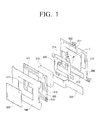
- FIG. 1 is a diagram illustrating an exploded perspective view of an image stabilizer, according to a first embodiment of the present invention
- FIG. 2 is a diagram illustrating a side view of the image stabilizer of FIG. 1 , according to an embodiment of the present invention
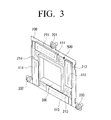
- FIG. 3 is a diagram illustrating a perspective view of the image stabilizer in an assembled state, according to an embodiment of the present invention
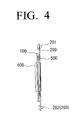
- FIG. 4 is a diagram illustrating a side view of the image stabilizer of FIG. 3 , according to an embodiment of the present invention
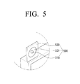
- FIG. 5 is a diagram illustrating an enlarged perspective view of the support unit of FIG. 1 , according to an embodiment of the present invention
- FIGS. 6-8 are diagrams illustrating an operation of the image stabilizer, according to an embodiment of the present invention.
- FIGS. 9 and 10 are diagrams illustrating a common grounded terminal shared by pattern coils, according to an embodiment of the present invention.
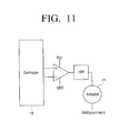
- FIG. 11 is a block diagram illustrating an actuator, according to an embodiment of the present invention.
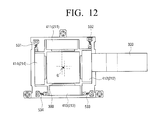
- FIGS. 12 and 13 are diagrams illustrating an image stabilizer having a support unit, according to a second embodiment of the present invention.
- FIG. 1 is a diagram illustrating a perspective view of an image stabilizer, according to a first embodiment of the present invention.
- FIG. 2 is a diagram illustrating a side view of FIG. 1 .
- FIG. 3 is a diagram illustrating a perspective view of the image stabilizer in an assembled state.
- FIG. 4 is a diagram illustrating a side view of FIG. 3 .
- the image stabilizer includes a first yoke 100, a second yoke 200, a driving frame 300, a coil plate 400, a support unit 500, and a glass cover 600.
- the first yoke 100 is composed of magnetic material, such as steel, and forms an exterior of the image stabilizer.
- the second yoke 200 is composed of magnetic material that is the same as the first yoke 100, and is fixed to a camera body. As shown in FIG. 3 , the second yoke 200 may be fixed and supported at three points, specifically, at an upper fixing portion 201 and two lower fixing portions 202, 203, so that an assembly error in pitch/yaw directions can be minimized.
- first through fourth magnets 211-214 are disposed on the second yoke 200.
- the first through fourth magnets 211-214 are arranged so as to be rotation-symmetric with respect to a center of the second yoke 200.
- the first and the second magnets 211, 212 are arranged perpendicular to each other
- the second and the third magnets 212, 213 are arranged perpendicular to each other
- the third and the fourth magnets 213, 214 are arranged perpendicular to each other
- the fourth and the first magnets 214, 211 are arranged perpendicular to each other.
- the magnets are formed in a rectangular shape and are the same size.
- each magnet 211-214 is arranged such that its lengthwise surface faces a surface on which an imaging unit 310 is disposed.
- the driving frame 300 is interposed between the first and the second yokes 100, 200 and is movable in a vertical direction, a horizontal direction, and in a rotation direction with respect to an optical axis.
- the imaging unit 310 is mounted in and fixed to a center of the driving frame 300.
- the imaging unit 310 may be a CCD or a CMOS chip set, and is connected to a controller (not shown) through a Flexible Printed Circuit (FPC) 320.
- FPC Flexible Printed Circuit
- the coil plate 400 is connected to a surface of the driving frame 300 facing the first yoke 100, and includes an inner circumference enclosing a circumference of the driving frame 300.
- the coil plate 400 includes first through fourth pattern coils 411-414 arranged on locations corresponding to the first through fourth magnets 211-214, for forming magnetism. Since the driving frame 300 is press-fitted into the coil plate 400, the driving frame 300 is moved in association with the coil plate 400 when the coil plate 400 is moved due to the interaction between the first through fourth pattern coils 411-414 and the first through fourth magnets 211-214.
- the first pattern coil 411 has a closed loop including a first coil 411a which is formed at a location facing an N pole and a second coil 411b which is formed at a location facing an S pole, and thus has opposite ends connected to a positive (+) pole and a negative (-) pole, respectively.
- the second through fourth pattern coils 412-414 have the same configuration as the first pattern coil 411, involving respective first and second coils 412a, 412b, 413a, 413b, 414a and 414b.
- first through fourth pattern coils 411-414 and the first through fourth magnets 211-214 is described in greater detail below.
- the support unit 500 is disposed on a surface of the driving frame 300 facing the second yoke 200 and supports the driving frame 300 in three-axis directions, specifically, pitch/yaw/roll directions with respect the second yoke 200.
- the support unit 500 includes a ball 510 and a support plate 520 as shown in FIG. 5 .
- the ball 510 is in roll-contact with the second yoke 200 and supports the driving frame 300 so that the driving frame 300 is moved in the pitch/yaw/roll 3-axis directions with respect to the second yoke 200.
- the support plate 520 extends from the driving frame 300 and has a recess 521 to receive the ball 510 and thus the ball 510 is rolling on the second yoke 200 when the driving frame 300 is moved.
- the support plate 520 may be disposed such that the support plate 520 does not interfere with the first through fourth magnets 211-214 and the first through fourth pattern coils 411-414, as shown in FIGS. 1-4 .
- the support unit 500 includes first through fourth elastic members 531-534, each having one end connected to the driving frame 300 and another other end connected to the second yoke 200.
- the first through fourth elastic members 531-534 are disposed such that they do not interfere with the first through fourth magnets 211-214 and the first through fourth pattern coils 411-414, as shown in FIGS. 12 and 13 .
- the first through the fourth elastic members 531-534 may be plate springs having a pleat shape. As shown in FIGS. 12 and 13 , the first and the third elastic members 531, 533 are arranged such that their lengthwise directions are parallel to the pitch direction, and the second and the fourth elastic members 532, 534 are arranged such that their lengthwise directions are parallel to the yaw direction. According to a system configuration, the directions in which the first through fourth elastic members 531-534 are arranged are variable.
- each elastic member 531-534 elastically supports the driving frame 300 in yaw/pitch/roll directions, while maintaining a predetermined gap between the driving frame 300 and the second yoke 200, even if the driving frame 300 is moved in the yaw/pitch/roll 3-axis directions.
- the image stabilizer moves the imaging unit 310 in order to stabilize an image.
- the image stabilizer is an actuator of a Voice Coil Motor (VCM) method using an electromagnetic field, and includes the first through fourth pattern coils 411-414 and the first through forth magnets to correct movement of the imaging unit 310 in the pitch/ yaw directions. Therefore, in order to correct movement of the imaging unit 310 in the roll direction, electromagnetic force may be sequentially generated at the first through fourth pattern coils 411-414 or different poles may be formed between neighboring pattern coils.
- a differential driving force is generated at each of the pattern coils 411-414 and a rotational force is generated by a moment force caused by the differential driving force.
- the magnet has an N pole and an S pole in the same plane in order to generate a great force smoothly.
- the pattern coil is formed to have a rectangular structure. Also, the pattern coil is arranged on the magnet with an air gap being formed on the upper surface of the magnet. The pattern coil determines a direction of an electromagnetic force according to a direction of current flowing in the pattern coil.
- FIG. 6 is a diagram illustrating the first through fourth magnets 211-214 and the first through fourth pattern coils 411-414 of the image stabilizer, according to an embodiment of the present invention.
- the driving frame 300 In order to drive the imaging unit 310 (see FIG. 1 ), the driving frame 300 (see FIG. 1 ) is required as an element for holding the imaging unit 310.
- the coil plate 400 on which the first through fourth pattern coils 411-414, interacting with the first through fourth magnets 211-214, are formed, is connected with the driving frame 300 in order to move the driving frame 300.
- the first through fourth magnets 211-214 may be formed on the driving frame 300, whereas the first through fourth pattern coils 411-414 may be formed on the second yoke 200.
- the weight of the first through fourth pattern coils 411-414 is lighter than the weight of the first through fourth magnets 211-214 in general, it is more preferable that the first through fourth magnets 211-214 are formed on the second yoke 200, which is a fixed structure, and the first through fourth pattern coils 411-414 are formed on the driving frame 300, which is a movable structure.
- the imaging unit 310 should be moved in a plane direction (pitch/yaw directions) which is perpendicular to an optical axis.
- the support plate 520 extending from the driving frame 300 is provided as a support structure and the ball 510 seated in the recess 521 of the support plate 520 supports the movement of the driving frame 300 in not only the pitch/yaw directions, but also the roll direction with respect to the second yoke 200.
- a metal pin may be inserted or mounted in the support plate 520 if the first through fourth magnets 211-214 are formed on the driving frame 300.
- response performance may deteriorate.
- the first magnet 211 is arranged in an off-set manner such that a center 211 d of the first magnet 211 is located a predetermined distance 'gl' away from a center G of the second yoke 200, which corresponds to an optical axis. Also, as shown in FIG. 6 , centers 212d-214d of the second through fourth magnets 212-214 are located the same distance 'gl' away from the center G of the second yoke 200. As a consequence, the first through fourth magnets 211-214 are eccentrically symmetrical with respect the center G of the second yoke 200.
- An N pole 211 a of the first magnet 211 is located on an upper side and an S pole 211 b is located on a lower side, as shown in FIG. 7 .
- the first coil 411 a of the first pattern coil 411 is located at the N pole 211a of the first magnet 211, and the second coil 411b of the first pattern coil 411 is located at the S pole 211b of the first magnet 211.
- a positive (+) pole and a negative (-) pole are connected to opposite ends of the first pattern coil 411.
- the negative (-) pole is grounded.
- the third magnet 213 is arranged such that an N pole 213a and an S pole 213b are arranged in the same direction as those of the first magnet 211.
- an N pole 212a of the second magnet 212 is located on a left side and an S pole 212b is located on a right side in FIG. 7 .
- the first coil 412a of the second pattern coil 412 is located at the N pole 212a of the second magnet 212 and the second coil 412b of the second pattern coil 412 is located at the S pole 212b of the second magnet 212.
- a positive (+) pole and a negative (-) pole are connected to opposite ends of the second pattern coil 412.
- the negative (-) pole is grounded.
- the fourth magnet 214 is arranged such that an N pole 214a and an S pole 214b are arranged in the same direction as those of the second magnet 212.
- Forces generated by the electromagnetic force generated between the first through fourth magnets 211-214 and the first through fourth pattern coils 411-414, arranged on locations corresponding to the first through fourth magnets 211-214, are expressed by a first pitch force P1, a second pitch force P2, a first yaw force y1 and a second yaw force y2, as indicated by arrows in FIGS. 6 and 7 .
- the first and the second pitch forces p1, p2 and the first and the second yaw forces y1, y2 are controlled to have the same value so that hand-shake correction for the pitch/yaw directions can be achieved as in a general image stabilizer.
- the driving frame 300 is rotated in the counter clockwise direction due to the difference between the forces.
- the number of power lines to apply current to the coils is four, specifically, two power lines for the positive (+) pole and the negative (-) pole of the pitch direction, and two power lines for the positive (+) pole and the negative (-) pole of the yaw direction.
- the pattern coils 411-414 should be driven individually in the different directions in order to move the imaging unit 310 in the roll direction. Accordingly, additional four power lines are required and thus 8 power lines are required in total.
- an increase in the number of power lines to apply current to the coils causes an increase in thickness of the FPC 320 and an increase in weight of the FPC 320 deteriorates the correcting operation of the imaging unit 310.
- the increase in the weight of the FPC 320 may be regarded as an important factor to deteriorate a servo characteristic.
- the negative (-) poles of the first through the fourth patterns coils 411-414 are grounded by being connected to a single terminal, and the single terminal is connected to the FPC 320 to exchange signals.
- the number of lines of the FPC 320 is reduced from 8 to 5. Therefore, as the width of the FPC 320 is reduced, the weight of the FPC 320 is reduced. Accordingly, the response performance can be improved due to the reduction in the weight of the FPC 320 connected with the imaging unit 310.
- FIG. 11 is a block diagram illustrating the image stabilizer, according to an embodiment of the present invention.
- the negative (-) pole is connected to the common grounded terminal and thus the number of terminals for controlling voltage is less than in an existing controller 10.
- FIGS. 12 and 13 are diagrams illustrating an image stabilizer, according to a second embodiment of the present invention.
- the image stabilizer operates in the same way as in the first embodiment.
- the difference from the first embodiment is that the support unit 500 is configured using an elastic member.
Landscapes
- Engineering & Computer Science (AREA)
- Multimedia (AREA)
- Signal Processing (AREA)
- Adjustment Of Camera Lenses (AREA)
- Studio Devices (AREA)
Applications Claiming Priority (1)
| Application Number | Priority Date | Filing Date | Title |
|---|---|---|---|
| KR1020090101875A KR101074034B1 (ko) | 2009-10-26 | 2009-10-26 | 손떨림 보정장치 |
Publications (3)
| Publication Number | Publication Date |
|---|---|
| EP2315432A2 true EP2315432A2 (fr) | 2011-04-27 |
| EP2315432A3 EP2315432A3 (fr) | 2016-08-10 |
| EP2315432B1 EP2315432B1 (fr) | 2019-12-04 |
Family
ID=43063202
Family Applications (1)
| Application Number | Title | Priority Date | Filing Date |
|---|---|---|---|
| EP10188370.0A Active EP2315432B1 (fr) | 2009-10-26 | 2010-10-21 | Appareil de stabilisation pour un capteur d'images. |
Country Status (3)
| Country | Link |
|---|---|
| US (1) | US8218957B2 (fr) |
| EP (1) | EP2315432B1 (fr) |
| KR (1) | KR101074034B1 (fr) |
Cited By (2)
| Publication number | Priority date | Publication date | Assignee | Title |
|---|---|---|---|---|
| CN111665677A (zh) * | 2020-04-29 | 2020-09-15 | 高瞻创新科技有限公司 | 折叠电路板结构 |
| US11762216B2 (en) | 2014-10-17 | 2023-09-19 | Lg Innotek Co., Ltd. | Lens moving apparatus |
Families Citing this family (20)
| Publication number | Priority date | Publication date | Assignee | Title |
|---|---|---|---|---|
| JP5580684B2 (ja) * | 2010-07-29 | 2014-08-27 | オリンパスイメージング株式会社 | 像振れ補正装置及びカメラ |
| KR101960493B1 (ko) * | 2012-12-12 | 2019-07-15 | 삼성전자주식회사 | 광학조절장치 |
| TWI490630B (zh) * | 2013-07-22 | 2015-07-01 | Tdk Taiwan Corp | 鏡頭驅動裝置及其製造方法 |
| JP6593990B2 (ja) * | 2014-12-24 | 2019-10-23 | キヤノン株式会社 | 像振れ補正装置、撮像装置、および光学装置 |
| JP6631046B2 (ja) * | 2015-06-16 | 2020-01-15 | リコーイメージング株式会社 | 駆動装置 |
| JP6659113B2 (ja) * | 2015-10-26 | 2020-03-04 | キヤノン株式会社 | 光学機器 |
| KR102046473B1 (ko) | 2017-03-08 | 2019-11-19 | 삼성전기주식회사 | 손떨림 보정 반사모듈 및 이를 포함하는 카메라 모듈 |
| CN116347238A (zh) * | 2018-06-29 | 2023-06-27 | Lg伊诺特有限公司 | 相机装置和光学仪器 |
| KR102589379B1 (ko) * | 2018-08-27 | 2023-10-16 | 엘지이노텍 주식회사 | 센서 구동 장치 및 카메라 모듈 |
| KR102869742B1 (ko) * | 2019-03-28 | 2025-10-14 | 엘지이노텍 주식회사 | 카메라 장치 |
| KR102233934B1 (ko) * | 2019-11-12 | 2021-03-30 | 삼성전기주식회사 | 손떨림 보정 반사모듈 및 이를 포함하는 카메라 모듈 |
| KR102901981B1 (ko) | 2019-11-18 | 2025-12-18 | 엘지이노텍 주식회사 | 카메라 모듈 및 광학 기기 |
| KR20220030723A (ko) * | 2020-09-03 | 2022-03-11 | 자화전자(주) | 카메라 액추에이터 및 이를 포함하는 카메라 모듈 |
| KR20220035622A (ko) * | 2020-09-14 | 2022-03-22 | 엘지이노텍 주식회사 | 렌즈구동장치, 카메라 모듈 및 광학기기 |
| EP4262188A4 (fr) | 2020-12-09 | 2024-09-25 | LG Innotek Co., Ltd. | Dispositif de caméra |
| CN112839176B (zh) * | 2021-01-18 | 2022-07-08 | 深圳市汇顶科技股份有限公司 | 芯片防抖装置、芯片、摄像模组及电子设备 |
| CN113163089B (zh) * | 2021-04-20 | 2025-02-11 | 河源友华微机电科技有限公司 | 影像感测模块及采用其的相机 |
| KR20230025991A (ko) * | 2021-08-17 | 2023-02-24 | 엘지이노텍 주식회사 | 센서 구동 장치 및 이를 포함하는 카메라 모듈 |
| KR102597175B1 (ko) * | 2021-11-15 | 2023-11-02 | 삼성전기주식회사 | 센서 시프트 모듈 및 이를 포함하는 카메라 모듈 |
| CN116320750A (zh) * | 2022-03-31 | 2023-06-23 | 常州市瑞泰光电有限公司 | 防振装置及摄像装置 |
Family Cites Families (15)
| Publication number | Priority date | Publication date | Assignee | Title |
|---|---|---|---|---|
| JPH0961880A (ja) | 1995-08-21 | 1997-03-07 | Canon Inc | レンズ鏡筒及びそれを用いた光学機器 |
| JP2001042408A (ja) * | 1999-07-30 | 2001-02-16 | Canon Inc | 撮像用装置 |
| JP4691326B2 (ja) * | 2004-06-08 | 2011-06-01 | Hoya株式会社 | 像ブレ補正装置 |
| US7679647B2 (en) * | 2004-07-21 | 2010-03-16 | Hewlett-Packard Development Company, L.P. | Flexible suspension for image stabilization |
| JP4606105B2 (ja) * | 2004-09-24 | 2011-01-05 | Hoya株式会社 | 像ブレ補正装置 |
| JP4564930B2 (ja) | 2006-02-28 | 2010-10-20 | 三星電子株式会社 | 手振れ補正装置 |
| WO2008012868A1 (fr) * | 2006-07-25 | 2008-01-31 | Tamron Co., Ltd. | dispositif de correction d'images et dispositif de formation d'images le comportant |
| KR101082615B1 (ko) * | 2006-08-23 | 2011-11-10 | 가부시키가이샤 리코 | 이미지 블러 보정 장치 및 이를 구비한 촬상 장치 |
| JP4943191B2 (ja) * | 2007-03-14 | 2012-05-30 | ペンタックスリコーイメージング株式会社 | カメラの手振れ補正装置 |
| US8139291B2 (en) * | 2007-05-21 | 2012-03-20 | Tamron Co., Ltd. | Image blur prevention actuator and lens unit and camera equipped therewith |
| KR101035791B1 (ko) | 2007-06-19 | 2011-05-20 | 자화전자(주) | 카메라 렌즈 어셈블리의 손떨림 보정 장치 |
| JP2009163089A (ja) | 2008-01-09 | 2009-07-23 | Canon Inc | レンズ鏡筒及びそれを有する光学機器 |
| KR101415038B1 (ko) * | 2008-01-16 | 2014-07-04 | 삼성전자주식회사 | 구동 시스템 및 이를 채용한 손떨림 보정장치 |
| JP4804564B2 (ja) * | 2009-07-14 | 2011-11-02 | キヤノン株式会社 | 振れ補正装置を有する光学機器 |
| KR101123732B1 (ko) * | 2009-09-04 | 2012-03-16 | 삼성전자주식회사 | 떨림 보정장치 |
-
2009
- 2009-10-26 KR KR1020090101875A patent/KR101074034B1/ko not_active Expired - Fee Related
-
2010
- 2010-08-13 US US12/856,329 patent/US8218957B2/en active Active
- 2010-10-21 EP EP10188370.0A patent/EP2315432B1/fr active Active
Non-Patent Citations (1)
| Title |
|---|
| None |
Cited By (4)
| Publication number | Priority date | Publication date | Assignee | Title |
|---|---|---|---|---|
| US11762216B2 (en) | 2014-10-17 | 2023-09-19 | Lg Innotek Co., Ltd. | Lens moving apparatus |
| EP3352000B1 (fr) * | 2014-10-17 | 2025-10-08 | LG Innotek Co., Ltd. | Appareil de déplacement de lentille |
| CN111665677A (zh) * | 2020-04-29 | 2020-09-15 | 高瞻创新科技有限公司 | 折叠电路板结构 |
| CN111665677B (zh) * | 2020-04-29 | 2022-04-08 | 高瞻创新科技有限公司 | 折叠电路板结构 |
Also Published As
| Publication number | Publication date |
|---|---|
| EP2315432A3 (fr) | 2016-08-10 |
| KR101074034B1 (ko) | 2011-10-17 |
| KR20110045343A (ko) | 2011-05-04 |
| US8218957B2 (en) | 2012-07-10 |
| EP2315432B1 (fr) | 2019-12-04 |
| US20110097061A1 (en) | 2011-04-28 |
Similar Documents
| Publication | Publication Date | Title |
|---|---|---|
| EP2315432B1 (fr) | Appareil de stabilisation pour un capteur d'images. | |
| CN102436118B (zh) | 透镜驱动装置以及照相机 | |
| CN102004366B (zh) | 影像稳定模组、取像模组及电子装置 | |
| US12625412B2 (en) | Camera actuator and camera module including the same | |
| JP5109450B2 (ja) | ブレ補正装置及び光学機器 | |
| US9298017B2 (en) | Lens driving device | |
| JP4844177B2 (ja) | ブレ補正装置及びカメラ | |
| KR101851912B1 (ko) | 위치 검출 장치 | |
| US20120300088A1 (en) | Electromagnetically Driven Device | |
| CN102165367A (zh) | 像抖动修正装置、摄像透镜单元和相机单元 | |
| KR20210031140A (ko) | 3축 흔들림 보정 기능을 구비한 카메라 모듈 | |
| WO2009069968A2 (fr) | Dispositif de correction de tremblement d'image | |
| CN102375287A (zh) | 影像稳定模组及成像装置 | |
| JP6206456B2 (ja) | カメラユニット、およびカメラ | |
| US9516231B2 (en) | Camera module | |
| KR101035791B1 (ko) | 카메라 렌즈 어셈블리의 손떨림 보정 장치 | |
| CN210781029U (zh) | 多轴光学防抖对焦装置、摄像模块以及电子设备 | |
| CN212540830U (zh) | 光学部件驱动装置、照相机装置以及电子设备 | |
| KR20090086755A (ko) | 카메라용 손떨림 보정 장치 | |
| JP2014191073A (ja) | 位置検出装置 | |
| JP2006106249A (ja) | ブレ補正撮像装置及びカメラ | |
| JP2000075338A (ja) | 像振れ補正装置とそれを用いた撮影装置 | |
| CN204906531U (zh) | 相机模块 | |
| KR102886224B1 (ko) | 자체 3축 짐벌 기능을 구비한 카메라 | |
| KR101671924B1 (ko) | 광학식 손떨림 보정장치 및 그가 적용되는 카메라 모듈 |
Legal Events
| Date | Code | Title | Description |
|---|---|---|---|
| PUAI | Public reference made under article 153(3) epc to a published international application that has entered the european phase |
Free format text: ORIGINAL CODE: 0009012 |
|
| AK | Designated contracting states |
Kind code of ref document: A2 Designated state(s): AL AT BE BG CH CY CZ DE DK EE ES FI FR GB GR HR HU IE IS IT LI LT LU LV MC MK MT NL NO PL PT RO RS SE SI SK SM TR |
|
| AX | Request for extension of the european patent |
Extension state: BA ME |
|
| RAP1 | Party data changed (applicant data changed or rights of an application transferred) |
Owner name: SAMSUNG ELECTRONICS CO., LTD. |
|
| PUAL | Search report despatched |
Free format text: ORIGINAL CODE: 0009013 |
|
| AK | Designated contracting states |
Kind code of ref document: A3 Designated state(s): AL AT BE BG CH CY CZ DE DK EE ES FI FR GB GR HR HU IE IS IT LI LT LU LV MC MK MT NL NO PL PT RO RS SE SI SK SM TR |
|
| AX | Request for extension of the european patent |
Extension state: BA ME |
|
| RIC1 | Information provided on ipc code assigned before grant |
Ipc: H04N 5/225 20060101AFI20160705BHEP Ipc: H04N 5/232 20060101ALI20160705BHEP |
|
| STAA | Information on the status of an ep patent application or granted ep patent |
Free format text: STATUS: REQUEST FOR EXAMINATION WAS MADE |
|
| 17P | Request for examination filed |
Effective date: 20161111 |
|
| RBV | Designated contracting states (corrected) |
Designated state(s): AL AT BE BG CH CY CZ DE DK EE ES FI FR GB GR HR HU IE IS IT LI LT LU LV MC MK MT NL NO PL PT RO RS SE SI SK SM TR |
|
| STAA | Information on the status of an ep patent application or granted ep patent |
Free format text: STATUS: EXAMINATION IS IN PROGRESS |
|
| 17Q | First examination report despatched |
Effective date: 20180502 |
|
| GRAP | Despatch of communication of intention to grant a patent |
Free format text: ORIGINAL CODE: EPIDOSNIGR1 |
|
| STAA | Information on the status of an ep patent application or granted ep patent |
Free format text: STATUS: GRANT OF PATENT IS INTENDED |
|
| INTG | Intention to grant announced |
Effective date: 20190627 |
|
| GRAS | Grant fee paid |
Free format text: ORIGINAL CODE: EPIDOSNIGR3 |
|
| GRAA | (expected) grant |
Free format text: ORIGINAL CODE: 0009210 |
|
| STAA | Information on the status of an ep patent application or granted ep patent |
Free format text: STATUS: THE PATENT HAS BEEN GRANTED |
|
| AK | Designated contracting states |
Kind code of ref document: B1 Designated state(s): AL AT BE BG CH CY CZ DE DK EE ES FI FR GB GR HR HU IE IS IT LI LT LU LV MC MK MT NL NO PL PT RO RS SE SI SK SM TR |
|
| REG | Reference to a national code |
Ref country code: GB Ref legal event code: FG4D |
|
| REG | Reference to a national code |
Ref country code: CH Ref legal event code: EP |
|
| REG | Reference to a national code |
Ref country code: AT Ref legal event code: REF Ref document number: 1210953 Country of ref document: AT Kind code of ref document: T Effective date: 20191215 |
|
| REG | Reference to a national code |
Ref country code: DE Ref legal event code: R096 Ref document number: 602010062223 Country of ref document: DE |
|
| REG | Reference to a national code |
Ref country code: IE Ref legal event code: FG4D |
|
| REG | Reference to a national code |
Ref country code: NL Ref legal event code: MP Effective date: 20191204 |
|
| REG | Reference to a national code |
Ref country code: LT Ref legal event code: MG4D |
|
| PG25 | Lapsed in a contracting state [announced via postgrant information from national office to epo] |
Ref country code: GR Free format text: LAPSE BECAUSE OF FAILURE TO SUBMIT A TRANSLATION OF THE DESCRIPTION OR TO PAY THE FEE WITHIN THE PRESCRIBED TIME-LIMIT Effective date: 20200305 Ref country code: NO Free format text: LAPSE BECAUSE OF FAILURE TO SUBMIT A TRANSLATION OF THE DESCRIPTION OR TO PAY THE FEE WITHIN THE PRESCRIBED TIME-LIMIT Effective date: 20200304 Ref country code: LT Free format text: LAPSE BECAUSE OF FAILURE TO SUBMIT A TRANSLATION OF THE DESCRIPTION OR TO PAY THE FEE WITHIN THE PRESCRIBED TIME-LIMIT Effective date: 20191204 Ref country code: ES Free format text: LAPSE BECAUSE OF FAILURE TO SUBMIT A TRANSLATION OF THE DESCRIPTION OR TO PAY THE FEE WITHIN THE PRESCRIBED TIME-LIMIT Effective date: 20191204 Ref country code: SE Free format text: LAPSE BECAUSE OF FAILURE TO SUBMIT A TRANSLATION OF THE DESCRIPTION OR TO PAY THE FEE WITHIN THE PRESCRIBED TIME-LIMIT Effective date: 20191204 Ref country code: LV Free format text: LAPSE BECAUSE OF FAILURE TO SUBMIT A TRANSLATION OF THE DESCRIPTION OR TO PAY THE FEE WITHIN THE PRESCRIBED TIME-LIMIT Effective date: 20191204 Ref country code: BG Free format text: LAPSE BECAUSE OF FAILURE TO SUBMIT A TRANSLATION OF THE DESCRIPTION OR TO PAY THE FEE WITHIN THE PRESCRIBED TIME-LIMIT Effective date: 20200304 Ref country code: FI Free format text: LAPSE BECAUSE OF FAILURE TO SUBMIT A TRANSLATION OF THE DESCRIPTION OR TO PAY THE FEE WITHIN THE PRESCRIBED TIME-LIMIT Effective date: 20191204 |
|
| PG25 | Lapsed in a contracting state [announced via postgrant information from national office to epo] |
Ref country code: RS Free format text: LAPSE BECAUSE OF FAILURE TO SUBMIT A TRANSLATION OF THE DESCRIPTION OR TO PAY THE FEE WITHIN THE PRESCRIBED TIME-LIMIT Effective date: 20191204 Ref country code: HR Free format text: LAPSE BECAUSE OF FAILURE TO SUBMIT A TRANSLATION OF THE DESCRIPTION OR TO PAY THE FEE WITHIN THE PRESCRIBED TIME-LIMIT Effective date: 20191204 |
|
| PG25 | Lapsed in a contracting state [announced via postgrant information from national office to epo] |
Ref country code: AL Free format text: LAPSE BECAUSE OF FAILURE TO SUBMIT A TRANSLATION OF THE DESCRIPTION OR TO PAY THE FEE WITHIN THE PRESCRIBED TIME-LIMIT Effective date: 20191204 |
|
| PG25 | Lapsed in a contracting state [announced via postgrant information from national office to epo] |
Ref country code: NL Free format text: LAPSE BECAUSE OF FAILURE TO SUBMIT A TRANSLATION OF THE DESCRIPTION OR TO PAY THE FEE WITHIN THE PRESCRIBED TIME-LIMIT Effective date: 20191204 Ref country code: RO Free format text: LAPSE BECAUSE OF FAILURE TO SUBMIT A TRANSLATION OF THE DESCRIPTION OR TO PAY THE FEE WITHIN THE PRESCRIBED TIME-LIMIT Effective date: 20191204 Ref country code: PT Free format text: LAPSE BECAUSE OF FAILURE TO SUBMIT A TRANSLATION OF THE DESCRIPTION OR TO PAY THE FEE WITHIN THE PRESCRIBED TIME-LIMIT Effective date: 20200429 Ref country code: EE Free format text: LAPSE BECAUSE OF FAILURE TO SUBMIT A TRANSLATION OF THE DESCRIPTION OR TO PAY THE FEE WITHIN THE PRESCRIBED TIME-LIMIT Effective date: 20191204 Ref country code: CZ Free format text: LAPSE BECAUSE OF FAILURE TO SUBMIT A TRANSLATION OF THE DESCRIPTION OR TO PAY THE FEE WITHIN THE PRESCRIBED TIME-LIMIT Effective date: 20191204 |
|
| PG25 | Lapsed in a contracting state [announced via postgrant information from national office to epo] |
Ref country code: SK Free format text: LAPSE BECAUSE OF FAILURE TO SUBMIT A TRANSLATION OF THE DESCRIPTION OR TO PAY THE FEE WITHIN THE PRESCRIBED TIME-LIMIT Effective date: 20191204 Ref country code: IS Free format text: LAPSE BECAUSE OF FAILURE TO SUBMIT A TRANSLATION OF THE DESCRIPTION OR TO PAY THE FEE WITHIN THE PRESCRIBED TIME-LIMIT Effective date: 20200404 Ref country code: SM Free format text: LAPSE BECAUSE OF FAILURE TO SUBMIT A TRANSLATION OF THE DESCRIPTION OR TO PAY THE FEE WITHIN THE PRESCRIBED TIME-LIMIT Effective date: 20191204 |
|
| REG | Reference to a national code |
Ref country code: DE Ref legal event code: R097 Ref document number: 602010062223 Country of ref document: DE |
|
| REG | Reference to a national code |
Ref country code: AT Ref legal event code: MK05 Ref document number: 1210953 Country of ref document: AT Kind code of ref document: T Effective date: 20191204 |
|
| PLBE | No opposition filed within time limit |
Free format text: ORIGINAL CODE: 0009261 |
|
| STAA | Information on the status of an ep patent application or granted ep patent |
Free format text: STATUS: NO OPPOSITION FILED WITHIN TIME LIMIT |
|
| PG25 | Lapsed in a contracting state [announced via postgrant information from national office to epo] |
Ref country code: DK Free format text: LAPSE BECAUSE OF FAILURE TO SUBMIT A TRANSLATION OF THE DESCRIPTION OR TO PAY THE FEE WITHIN THE PRESCRIBED TIME-LIMIT Effective date: 20191204 |
|
| 26N | No opposition filed |
Effective date: 20200907 |
|
| PG25 | Lapsed in a contracting state [announced via postgrant information from national office to epo] |
Ref country code: PL Free format text: LAPSE BECAUSE OF FAILURE TO SUBMIT A TRANSLATION OF THE DESCRIPTION OR TO PAY THE FEE WITHIN THE PRESCRIBED TIME-LIMIT Effective date: 20191204 Ref country code: SI Free format text: LAPSE BECAUSE OF FAILURE TO SUBMIT A TRANSLATION OF THE DESCRIPTION OR TO PAY THE FEE WITHIN THE PRESCRIBED TIME-LIMIT Effective date: 20191204 Ref country code: AT Free format text: LAPSE BECAUSE OF FAILURE TO SUBMIT A TRANSLATION OF THE DESCRIPTION OR TO PAY THE FEE WITHIN THE PRESCRIBED TIME-LIMIT Effective date: 20191204 |
|
| PG25 | Lapsed in a contracting state [announced via postgrant information from national office to epo] |
Ref country code: IT Free format text: LAPSE BECAUSE OF FAILURE TO SUBMIT A TRANSLATION OF THE DESCRIPTION OR TO PAY THE FEE WITHIN THE PRESCRIBED TIME-LIMIT Effective date: 20191204 |
|
| REG | Reference to a national code |
Ref country code: DE Ref legal event code: R119 Ref document number: 602010062223 Country of ref document: DE |
|
| REG | Reference to a national code |
Ref country code: CH Ref legal event code: PL |
|
| PG25 | Lapsed in a contracting state [announced via postgrant information from national office to epo] |
Ref country code: LU Free format text: LAPSE BECAUSE OF NON-PAYMENT OF DUE FEES Effective date: 20201021 Ref country code: MC Free format text: LAPSE BECAUSE OF FAILURE TO SUBMIT A TRANSLATION OF THE DESCRIPTION OR TO PAY THE FEE WITHIN THE PRESCRIBED TIME-LIMIT Effective date: 20191204 |
|
| REG | Reference to a national code |
Ref country code: BE Ref legal event code: MM Effective date: 20201031 |
|
| PG25 | Lapsed in a contracting state [announced via postgrant information from national office to epo] |
Ref country code: FR Free format text: LAPSE BECAUSE OF NON-PAYMENT OF DUE FEES Effective date: 20201031 Ref country code: DE Free format text: LAPSE BECAUSE OF NON-PAYMENT OF DUE FEES Effective date: 20210501 |
|
| PG25 | Lapsed in a contracting state [announced via postgrant information from national office to epo] |
Ref country code: BE Free format text: LAPSE BECAUSE OF NON-PAYMENT OF DUE FEES Effective date: 20201031 Ref country code: CH Free format text: LAPSE BECAUSE OF NON-PAYMENT OF DUE FEES Effective date: 20201031 Ref country code: LI Free format text: LAPSE BECAUSE OF NON-PAYMENT OF DUE FEES Effective date: 20201031 |
|
| PG25 | Lapsed in a contracting state [announced via postgrant information from national office to epo] |
Ref country code: IE Free format text: LAPSE BECAUSE OF NON-PAYMENT OF DUE FEES Effective date: 20201021 |
|
| PG25 | Lapsed in a contracting state [announced via postgrant information from national office to epo] |
Ref country code: TR Free format text: LAPSE BECAUSE OF FAILURE TO SUBMIT A TRANSLATION OF THE DESCRIPTION OR TO PAY THE FEE WITHIN THE PRESCRIBED TIME-LIMIT Effective date: 20191204 Ref country code: MT Free format text: LAPSE BECAUSE OF FAILURE TO SUBMIT A TRANSLATION OF THE DESCRIPTION OR TO PAY THE FEE WITHIN THE PRESCRIBED TIME-LIMIT Effective date: 20191204 Ref country code: CY Free format text: LAPSE BECAUSE OF FAILURE TO SUBMIT A TRANSLATION OF THE DESCRIPTION OR TO PAY THE FEE WITHIN THE PRESCRIBED TIME-LIMIT Effective date: 20191204 |
|
| PG25 | Lapsed in a contracting state [announced via postgrant information from national office to epo] |
Ref country code: MK Free format text: LAPSE BECAUSE OF FAILURE TO SUBMIT A TRANSLATION OF THE DESCRIPTION OR TO PAY THE FEE WITHIN THE PRESCRIBED TIME-LIMIT Effective date: 20191204 |
|
| PGFP | Annual fee paid to national office [announced via postgrant information from national office to epo] |
Ref country code: GB Payment date: 20230920 Year of fee payment: 14 |
|
| GBPC | Gb: european patent ceased through non-payment of renewal fee |
Effective date: 20241021 |
|
| PG25 | Lapsed in a contracting state [announced via postgrant information from national office to epo] |
Ref country code: GB Free format text: LAPSE BECAUSE OF NON-PAYMENT OF DUE FEES Effective date: 20241021 |