EP2315544B1 - Élément receveur de douche en mousse - Google Patents
Élément receveur de douche en mousse Download PDFInfo
- Publication number
- EP2315544B1 EP2315544B1 EP09782198.7A EP09782198A EP2315544B1 EP 2315544 B1 EP2315544 B1 EP 2315544B1 EP 09782198 A EP09782198 A EP 09782198A EP 2315544 B1 EP2315544 B1 EP 2315544B1
- Authority
- EP
- European Patent Office
- Prior art keywords
- shower
- base element
- drain
- drainage line
- foam
- Prior art date
- Legal status (The legal status is an assumption and is not a legal conclusion. Google has not performed a legal analysis and makes no representation as to the accuracy of the status listed.)
- Active
Links
Images









Classifications
-
- E—FIXED CONSTRUCTIONS
- E03—WATER SUPPLY; SEWERAGE
- E03C—DOMESTIC PLUMBING INSTALLATIONS FOR FRESH WATER OR WASTE WATER; SINKS
- E03C1/00—Domestic plumbing installations for fresh water or waste water; Sinks
- E03C1/12—Plumbing installations for waste water; Basins or fountains connected thereto; Sinks
- E03C1/28—Odour seals
-
- A—HUMAN NECESSITIES
- A47—FURNITURE; DOMESTIC ARTICLES OR APPLIANCES; COFFEE MILLS; SPICE MILLS; SUCTION CLEANERS IN GENERAL
- A47K—SANITARY EQUIPMENT; ACCESSORIES THEREFOR, e.g. TOILET ACCESSORIES
- A47K3/00—Baths; Showers; Appurtenances therefor
- A47K3/16—Devices for fastening baths to floors or walls; Adjustable bath feet ; Lining panels or attachments therefor
- A47K3/1605—Hard foam bathtub supports
-
- A—HUMAN NECESSITIES
- A47—FURNITURE; DOMESTIC ARTICLES OR APPLIANCES; COFFEE MILLS; SPICE MILLS; SUCTION CLEANERS IN GENERAL
- A47K—SANITARY EQUIPMENT; ACCESSORIES THEREFOR, e.g. TOILET ACCESSORIES
- A47K3/00—Baths; Showers; Appurtenances therefor
- A47K3/28—Showers or bathing douches
- A47K3/40—Pans or trays
Definitions
- the invention relates to a foam shower floor element, preferably plate-like foam shower floor element, with a drain, wherein the drain has a pot bottom drain pot and formed by a high-altitude flow diversion odor trap and runs from the drain pot drain line to an edge of the shower floor element.
- Foam shower floor elements in the aforementioned plate-like design, for the formation of floor-level showers have already become known in various embodiments. It is for example on the DE 203 11 666 U1 directed. The state of the art is also on the WO2007 / 02314 A1 directed.
- a foam shower floor element which identifies a simple drain pipe.
- a drainage conduit having an oblique arrangement and having a cross-sectional sword-like projection from the top wall of the drainage conduit over the length between two corresponding projections from the bottom of the drainage conduit slightly overlapping in said cross-section Odor trap forms.
- the DE-U-201 00 829 shows a drain with odor trap for a bath or shower tray to be mounted. An outlet pipe directly following the odor trap runs diagonally downwards.
- the invention has the object to provide an advantageous foam shower floor element.
- the process can, at least in part, be readily preassembled and, in particular, pre-sealed into the shower floor element at the factory.
- the seal is preferably achieved by an adhesive layer (see also below), optionally, in particular in a transition region to the drain or the drain line also by conventional sealing tapes or a continuous sealing film.
- an actual drain pot is formed in the sense of a cylindrical part. It can also be a deflection, usually from the vertical to the horizontal, act, which is followed by the drain line. As a drain pot here the region of the sequence is addressed in any case, which first runs full in drainage through the flow of the shower tray element until an overflow into such, arranged in the flow direction behind areas of the drain line occurs. It can also be provided, regardless of further water inclusions by vertical deflection of the drain line that in the region of the drain pot itself a complete water seal (odor trap) is already given.
- the odor trap Due to the height-different leadership of the drain line and possibly also provided in the drain pot itself flow-Umlenkschikane, remains in the pot or said deflection a certain water level are preferred, which can thus form part of the odor trap.
- the odor trap is known to be formed by a re-rising portion, or between two rising portions of the line. With regard to the flat design of the odor trap, which is indicated with regard to the placement in the thickness of the plate-like shower tray element, it may also be advisable to provide such an odor trap two times in the longitudinal extension of the drain line one behind the other.
- the drain pipe is wave-shaped. This means that the discharge line runs in a longitudinal cross section, a cross section in the flow direction, alternately up and down. "All in all” In this case, it is preferred that the change in height is of such a magnitude that, after the change, a line bottom extends in a horizontal plane or above a line blank before the change. This with a rise angle and a descent angle.
- the rise and / or fall angle in the range of 35 to 55 °, in particular 40 to 50 °.
- the angle data based on the course of the subfloor, in the cross section of the drain line.
- the upper floor or ceiling area of the drain line can have lower rise and fall angles, this also because it can come in the range of height changes to a cross-sectional reduction of the line.
- the rise and / or fall angle is therefore preferably in the range of 20 to 40 °.
- all intermediate values in particular in 1 ° increments, are also included in the disclosure. In any case, it can be seen that the angles of rise and descent are preferably acute angles.
- the formed by a longitudinal cross-section hump-like course of the floor bottom forms flow obstacles, wherein the formed in the sense of a Martinezarnake Deckenbuckels line cover is pulled down so far that it protrudes below the humpback peaks of the ground flow obstacles and so allows an odor trap, alone through the drain line , is formed outside the drain pot.
- the initially formed in the flow direction bottom flow obstacle here represents with its rising edge at the same time the conclusion of the drain pot.
- the descending flank is part of the formed in the drain line odor trap.
- the subsequent second floor flow obstacle complements with its rising edge, the descending flank of the first soil flow obstacle and continues to form so in cooperation with the opposing Deckenbuckel the odor trap within the drain line.
- the descending flank of the second bottom flow obstacle also forms the transition into the subsequent customary, preferably formed with a circular cross-section, drain line.
- a distance between the bottom flow obstructions, seen in the direction of flow, may correspond to 2 to 10 times the said free vertical dimension.
- the drain is in any case formed up to the uppermost region of the second bottom flow obstruction having a width which exceeds the thickness of the shower tray element.
- a width which corresponds to more than the thickness of the shower tray element, in particular 1.1 to 3 times the shower tray element, wherein all intermediate values are included in the disclosure in particular in 1/10 steps corresponds.
- the drain pot can be adapted over its full height to the gutter extension (ie, instead of round, be elongated). But it can also be provided only in an upper region, the elongated design of the drain pot. Further, even with the usual round drain pot, which is optionally formed with a slightly smaller vertical extent, a gutter be placed so that the gutter bottom opens directly into the drain pot.
- the floor flow obstacles fit in their respective lower area in the bottom surface of the shower floor element, so possibly form part of the bottom surface of the shower floor element at the same time.
- the mentioned bridge-like training in the field of flow obstacles is also advantageous in terms of stability. It provides a vault structure that can contribute favorably to the overall stability of the process and also floor element with clamped drainage. In this case, it is also of particular importance that the extent of such a vault, ie from bottom section to bottom section, is about 1 to 3 times, preferably 2 times, whereby here also all intermediate values, in particular in 1/10 steps, in the disclosure is included, the thickness of the shower floor element corresponds.
- the drain pot possibly by means of an inlet part inserted or screwed therein, opens at the level of the lower stage and preferably also extends only in the height range of the lower stage.
- the drain can be installed in the lower plate part, for instance by simply inserting it from above, and the upper plate part can then be provided so that it does not have to take any function with regard to the drain.
- the shower tray element has a bottom surface and that the bottom of the drain pot extends in the bottom surface. At most, it may be up to the underside surface which is 10 mm or less.
- the integration of the drain pot in the underside surface of the shower floor element is an integration of the drain pot in the bottom, the support surface, the plate-like shower floor element. In this respect, an alignment of a bottom region of the drain pot, preferably if it extends planar, with the underside surface is preferred. It may also be about several, with their tips located in a common (flat) surface, bottom projections.
- the measure to provide the drain line at a height of the bottom of the pot or higher it is preferred in view of running at different heights drain line that at least a lower wall region of the drain line above a height level of the pot bottom - in sections - runs.
- the drainage line runs at least partially flush with the underside surface of the shower tray element or with a distance of 10 mm or less from the underside surface.
- the drain line has a width exceeding a vertical extent of the shower tray element.
- a width of the plate-like shower tray element in particular a thickness of 100 mm or less, a favorable drainage performance can be achieved.
- this can also be achieved in the areas in which the drain line is included in the upper or lower surface of the plate-like shower tray element, a favorable area support.
- the drain line can also correspond at least over a partial length of the thickness of the shower floor element. At least over this partial length, the shower floor element is formed in this area in the thickness direction alone by the drain line.
- the drain line in which the drain line runs almost or flush with an upper side or a lower side surface of the shower floor element, the drain line is also integrated into the support structure of the shower floor element.
- the foamed structure of the shower tray element outside the drain pot or a drain grate leaves a passage opening receiving the drain line (in the vertical direction).
- This passage opening can extend in terms of their length over a third or more, based approximately on a rectangular floor plan, a longitudinal side of the shower tray element.
- the drain pot or the drain grate located above it is preferably arranged approximately centrally of the plate-like shower tray element. This is because due to the described design of the drain line with regard to the formation of the odor trap a certain length extension of the drain line is used alone to form the odor trap. This length extension, which is used to form the odor trap, can be about two to ten times a maximum diameter dimension of the drain line.
- the drain line at least partially and preferably in the area in which it - forms - with the odor trap, with a flattened, deviating from the circular profile, in particular one Rectangular profile is formed.
- Said passage opening is preferably designed like a keyhole.
- a further embodiment may also provide that the passage opening is rectangular, more preferably with a taper toward the edge.
- the taper can be provided such that initially over a portion of the walls of the opening wedge-shaped converge toward each other and then extend with a smaller distance to the edge back parallel to each other.
- a typical maximum width of the passage opening is in the range of 80 to 150 mm, more preferably 100 to 130 mm and in the narrow range 50 to 90 mm, preferably 70 mm.
- the discharge line in the region of the passage opening is a carrier for an adhesive layer for tiling.
- This adhesive layer can be applied directly to the drain line. It can also be applied to a cover plate covering the drain line. In this respect, in particular a solid plate part is preferred as a cover. It is also possible for the cover part to bridge over the drain line in the manner of a bridge, under the edge-side support on the foam shower floor element, in the region of said opening.
- the drain pipe should run as high or with the best possible use of the given thickness.
- it is also preferred, seen to the edge to provide a certain slope of the drain line after the completion of the trap, in order to further promote the process already in the floor plan area of the shower floor element.
- the gradient may be, for example, in the range of a few millimeters, about 5 to 10 mm per meter, given. Due to the different height leadership of the drain line to form the odor trap, this also has a certain elastic mobility, especially in the turning areas. If, for example, as preferred, after the deflections for the odor trap rectilinearly extending portion of the drain line predetermined a slope of, for example. 0.2 to 0.4%, ie a slight slope, this slope can also be due to said mobility elastic deformation can be easily increased to 1, 2, 3 up to, for example, 4%.
- the drain line is still provided with a foam wrapper, for example a soft foam wrapper, approximately as one generally knows from the jacket of heating pipes. Further preferably such that stomata remain up to a bottom of the shower floor element or, in the passage opening of the shaft, to a floor on which the shower floor element is set up during assembly.
- the thickness of the shower tray element is further preferred that this is 70 mm or less.
- the thickness of the shower tray member is 30 mm or more.
- the thickness is greatest in the edge region, since a gradient is usually formed on the upper side of the shower floor element to the process. The gradient can be at a shower floor element with an edge dimension of, for example, 1.2 times 1.2 m to a centrally planned drain 15 mm. Therefore, the thickness of the shower floor element, based on the edge side 70 mm, in the region of the immediate connection of the shower floor element to the drain pot with, for example, 55 mm specify.
- a typical ground plan dimension of the manufactured shower floor element is given in the range of 1100 by 1100 to 1300 by 1300 mm, preferably 1200 by 1200 mm.
- Such a shower floor element can be separated on the spot due to the preferred design, as explained below, then on site for adaptation to given dimensions. For example.
- the adjustment in one direction or in two mutually perpendicular directions can be shortened by up to one third, also because of the pre-sealed end of the discharge line, which is preferably provided with removal to an outer edge.
- a plate-like shower floor element is particularly advantageous in terms of the formation of a shower place composed of several plate-like shower floor elements.
- preferably only one, more preferably a central, shower floor element has the said drain with subsequent drain line, with partial formation of the trap through the drain line.
- the shower floor element consists of a drain and the drain line with the odor trap having base element.
- the preferred factory pre-sealed drain line, including the drain pot, which is also preferably integrally formed with the drain line can conclude with respect to a connection end for a to be connected during installation on-site drain forwarding with a peripheral edge of the base element.
- connection end can also protrude like a plug from the base element.
- it may be set back with respect to the peripheral edge.
- connection end it is particularly preferred that the connection end to is set back under a cover plate.
- the cover plate ends in this case at a distance from the peripheral edge of the base element.
- terminal end can be flush with the edge of the cover plate or be given further set back under the cover plate.
- the drain line can then be continued by connecting a drain forwarding, which is preferably by simple horizontal connector, possibly by means of a cross-sleeve, in the base element or a mounting element.
- a drain forwarding which is preferably by simple horizontal connector, possibly by means of a cross-sleeve, in the base element or a mounting element.
- the assembly of the base member with one or more attachments may be provided butting abutting.
- the sealing can also be provided a tooth-like meshing of edge portions of the base member and the attachment or the add-on elements, which are prestructured corresponding edge side.
- a sealing of the resulting joining region by a covering sealing tape or a covering sheet covering the surface, or possibly with edge overhang for connection to the surrounding soil or masonry may additionally be provided.
- the attachments may be formed in particular like a bolt, so with a rectangular plan and preferably also rectangular cross-section. In this case, they are furthermore preferably provided in a set, that is to say summarized or as additional parts for a shower floor element described here, such that at least one of the locking elements exceeds the marginal edge length of the shower floor element. So can be designed with the add-on elements cheap blunt abutting corners.
- shower floor element as described here, can be adapted to a favorable spatial extent, in particular by means of partitions parallel to it the drain line, accordingly offset laterally thereto, or in a region opposite to the extension of the drain line.
- the drain line has, in particular with regard to the non-circular cross-section already mentioned, at least over part of its extension to a horizontal dimension which is greater than the free vertical dimension.
- inventions described here are provided in particular as a gravity-driven sequence (passive sequence). However, they can also be provided with drain support, for example by means of an electric pump (active drain).
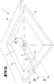
- a plate-like shower tray element 1 which consists essentially of a foam body 2.
- the foam may in particular be a particle foam.
- an EPS particle foam may also be an extruded foam, XPS foam.
- it can also be an integrally foamed foam, for example a polyurethane foam.
- the foam can be given here with a higher density to the outside; but it can also be a total homogeneously foamed foam.
- the plate-like shower tray element 1 in the embodiment has a thickness d of 70 mm. As can be seen, this is focused on the thickness in the edge region. Due to a gradient usually formed towards the slope, the thickness is immediately lower at the outlet. Compared to the edge, the thickness at the outlet, for example, by 5 to 20 mm lower, and this is particularly dependent on the overall size of the shower floor element.
- the foam element is provided with a bonding agent layer.
- a bonding agent layer may be a polymer dispersion, especially a non-reactive polymer dispersion.
- an acrylate dispersion can contain organic and / or mineral filler.
- the primer layer may also be made of a plastic-mortar combination consist. These are understood in particular mixtures of hydraulically setting binders (eg Portland cement). These may have mineral additives and / or organic additives and / or polymer dispersions as a proportion.
- the coating may also consist of another mortar coating.
- This primer layer allows to apply a sanitary surface in the form of tiles in a favorable manner. This is, for example, to understand a natural stone, possibly in the form of an integral plate, so for example. Natural stone slab.
- an integral sanitary surface consisting for example of an acrylic material, can also be applied to the plate-like shower tray element 1.
- a film cover serving also for this purpose may be provided. It may also, for example., If necessary, also act on the film cover to an epoxy resin coating.
- an XPS foam or a PU foam so in each case a cellular foam and no particle foam, is used, can be completely dispensed with such a cover layer or adhesive layer.
- Fig. 1 For example only tile parts of a tiling are indicated.
- a drain grate 3 is provided with an underlying drain pot 4.
- the drain grate 3 can in this case also be formed elongated trough-like. It can also be a drain gutter.
- an odor trap is provided in cooperation between the drain pot 4 and the drain line 5.
- This can be done first by a suitable, be given in the drawing not shown baffle in the region of the drain pot 4.
- the height-wise deflection which is basically indicated in the drawing, the drain line 5.
- the odor trap is at least partially outside of the drain pot 4 in cooperation with the drain line 5 is formed.
- the given height-wise flow deflection is due in particular to two deflection areas, the areas 6 and 7, the drain line 5.
- the drain line 5, as in more detail about Fig. 2 and also Fig. 4 results in this case runs in the entire shower floor element at a height of the pot bottom 8 or higher. In particular, when the pot bottom extends in the underside surface of the shower tray element. Overall, the drain line 5 runs within the thickness d of the shower tray element 1 in the mentioned leadership of the drain line 5 over different heights.
- the width is addressed by b, which is given in the area adjacent to the drain pot to the beginning of the taper to the connection part 12 out.
- This prolonged formation of the odor trap may also be expressed by, in combination with or independent of the reference to the width b of the drain line, that this area of the drain line 5 extends beyond a dimension which is more than the thickness d of the shower tray element, in particular a measure that is up to five times, further up to ten times or more of the thickness d of the shower floor element.
- the disclosure also includes all intermediate values, in particular in 1/10 thickness increments (based on the thickness d of the shower floor element). This illustrates the substantial lengthwise inclusion of the drain line 5 in the formation of the odor trap.
- the length of the through-passage 9 corresponds at least to the dimensions of the outlet, in particular the drainage pot 4 and the length of the drainage conduit 5, which are used in this direction and which are used to form the said odor trap. Preferably also beyond.
- this opening 9 is completed at the edge of the shower floor element by a remaining, so preferably integrally foamed wall 10.
- this wall 10 can be used as a wall for receiving a preferably then over a relevant end face 11 of the shower floor element 1 protruding connecting part 12 of the drain line. This facilitates the assembly and sealing. Further, the assembly and sealing can be facilitated by the fact that in the region of the grate and / or the drain pot and / or over the length of the drain line a Aufsetzcut is formed in the shower tray element. Then the drain part, so in particular the drain pot and / or the drain line, come in accordance with counter-stage training in the course of insertion from above for placement. A fall down is prevented.
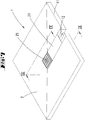
- Fig. 3 In an alternative embodiment, as in Fig. 3 is shown, are provided for the intended inclusion of the drain line in the shower floor element from above accessible recesses 13 which are interrupted by wall parts 14 left standing. Preferably, it is in the recesses 13 to fürgangsaus traditions.
- the wall parts 14 allow breaking and inserting the drain line 5 from above into the shower floor element.
- a plurality of such possible line guides can be provided in this way, so that a basic shape for the design of running in different directions drain lines can be used.
- the drain line 5 has at least in sections a rectangular cross-section.
- Essential is a larger dimension of the cross section in the horizontal direction than in the vertical direction. It may also be, for example, an oval cross-section.
- a dimension s of the drain line 5 is less than the thickness d of the shower floor element, at least in the subsequent area of the shower floor element.
- the already mentioned width dimension b at least in this area, but preferably also over the entire extent of the shower floor element, greater than the thickness d.
- the drainage line 5 runs at least in sections over its length on the underside with a bottom side surface 15 in alignment. It is included in the floor design of the shower floor element. On the upper side, if necessary, in sections, an aligned course may be provided with an upper side of the shower tray element.
- the drain line 5 is covered on the upper side by a cover plate part 16. This cover plate part 16 rests on the edge of the foam part.
- the drain line 5 is preferably integrated into the support structure of the shower floor element. This means that when a force acting on the vertical projection surface of the drain line, possibly reduced to this area, load the drain line contributes significantly to the stability. It has to absorb the corresponding burden.
- the already mentioned adhesion promoter layer can be applied for the direct application of tiles.
- a set-like composition may be provided by a base portion having associated therewith and attachments 18 associated therewith.
- Such an attachment 18 may also be provided with a primer layer or, if appropriate, a film serving for this purpose, in one of the embodiments as described above.
- a drain line continuation 19 which may be integrally formed on a plug-like projecting connection portion 20 of the drain line, with respect to the base part.
- the base part is selected with a size which is usually not undershot, for example 70 ⁇ 70, 80 ⁇ 80 or 90 ⁇ 90 cm, it is regularly not necessary during installation to change the already pre-sealed section of the drain line again , Rather, the possibly the installation conditions owed special installation can then be made alone in an attachment 18.
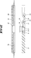
- Fig. 6 is a cross section through the shower floor element shown.
- the drain pot 4 is not formed to the bottom, the back surface of the shower floor element, throughout. However, this can nevertheless also be provided.
- the drain line 5 would also connect to the underside and not first perform a curvature down, but initially a curvature upward. In any case, concerning the lower wall of the drain line 5.
- the latter design is particularly favorable if, as preferred, already in the drain pan 5 a water level remains, so a part of the odor trap is completed.
- the cross-sectional profile of the drain line 5 can change.
- a rectangular cross-section is preferably provided.
- 5% or more of their respective length range is formed with a round cross-section.
- a drain line instead of a drain line and in order to accommodate a certain amount of water, in such a shower floor element - also preferably factory pre-sealed - several such drain lines in one of the described embodiments, which then preferably connect to a common drain pot, be provided.
- Fig. 6 shows that the already pre-sealed drain line 5 has a protruding from the edge 10 side plug-like connection piece 12.
- a further laying of the drain line can be connected to this without the Voreindichtung the drain line 5 would have to be touched in the base part.
- the invention can be realized by a method, which is not included in the scope of protection, for forming a shower area, which is composed of a plurality of plate-like foam shower floor elements, wherein a base part and one or more attachments are provided in the base part at the factory Drain and a drain line are sealed to form an odor trap, and further wherein the drain line associated with an edge of the base part in the base part has a terminal end and the installation adjustment only in terms an attachment is made or that an adjustment takes place only by separating the base part, without damaging the Voreindichtung.
- Installation adaptation here means cutting or separating such a foam part.
- the base part is this either in a (small) standard size, ie in various combinations always in the same size dimension, provided or in a large standard size, eg. The above mentioned 1200 times 1200 mm, so that in most cases only a reduction of the base part is required. In this case, no sealing connections with regard to add-on parts are required, although attachment parts can also be attached to such a base part of a large standard size.
- "Factory" means on the one hand, that the possibilities of mass production are used, such parts are always practically the same, and / or on the other hand, that a shower floor element with such pre-sealed drainage already by a plumber, at a dealer, especially wholesalers are purchased can.
- the Voreindichtung refers evidently to the drain pot (edge with respect to the relevant opening of the shower floor element) and the preferably integrally formed drain line up to said terminal end and, as far as provided, beyond the Voreindichtung a drain line cross-over closure member, the closure of the shaft, in which the drain line extends, upwards, so in particular the described plate part.
- a separate drain grate carrier see cover 45 in Fig. 10 ). The latter also with respect to the seal in the shower floor element, but also with respect to the seal to the drain pot.
- a method for manufacturing and assembly of a shower tray element wherein the shower tray element has a drain, a drain line and an outlet formed in the drain and / or drain trap, further wherein the drain line has a terminal end , in which case it is further essential that the process and the discharge line, including the odor trap, are factory pre-sealed, the connection end is factory provided at a horizontal distance from the drain, wherein, according to an at least partially upwardly open shaft into which the drain line extends, the connection end already at a location on the ground resting shower floor element remains accessible from the outside for visual inspection, which is further connected under horizontal mating assignment during assembly at an installation a drain forwarding and is checked on resting shower floor element, the tightness of the connection of the drain forwarding.
- a distance of one tenth to one third of the factory default size dimension, ie, for example, the width of 1300.1200 etc. mm, allows with respect to the connection of the drain-forward still required leak test in already resting on the floor and with the floor, for example. Bonded shower floor element at the installation.
- the shaft is then still open and it can be poured into the drain pot of water. With the eye, the junction of the pre-sealed drain line to the drain forwarding can be completely checked in so far just already lying at its final installation location and possibly anchored shower floor element.
- the shaft eg. In the already written way, can be filled and closed.
- the configuration of the shower floor element with respect to the connection of the drainage-forwarding should allow a simple, horizontal plug-in or overlap mounting, for example with a sleeve part. No vertical connection work is required.
- FIGS. 7 to 9 is a modified with respect to the expiration part embodiment of such a shower floor element shown and described.
- the here integrated drain part which also in the Figures 14 and 15 is shown in detail, initially has a drain pot 4, in which an insert part 21 is inserted.
- This insert 21 provides together with the pot boundary, which is given here by the bottom 22 of the pot or the transition into the drain line, a first odor trap.
- a first filling of the drain part results in a water level before it comes to the inlet in the area after the first bottom hump 23, as indicated by the line L. Since this line L extends above a lower edge 24 of the insert part 21, thus results in the region of the drain pot thereby a first odor trap.
- a first volume of water is provided in the insert 21 from the waterline L to the lower edge 24 of the insert.
- a second volume of water is provided in the drain pot 4 from the waterline L to its bottom, minus the first volume of water.
- a third, possible (refilling) volume of water is in the insert 21 of the now, for example, in Fig. 9 given waterline L to the drain grate 3, including the radial magnification below the drain grate 3 and above the upper edge of the insert part 21.
- the drain pot is preferably formed so that the water line L with the ceiling of the drain pot 4, which is radially outward of the drain grate 3 is in the normal state coincides.
- the proportions of the drain pot 4 and the insert part 21 and the drain grate 3, the said radial enlargement by its downward protruding edge, are preferably provided so that the first volume of water corresponds to one third to two thirds, more preferably half, of the second volume of water.
- the third volume of water is equal to or greater than the first volume of water, preferably in the range of 0.8 to 1.5 times the first volume of water. All interim values, in particular in one-tenth steps, are also included in the disclosure in the aforementioned water volume ratios.
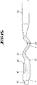
- drain line is wave-shaped. In the cross section of the shower tray element it changes from bottom to top, back down and back up and then goes over into the connection part 12th
- connection part 12 Up to the transition into the connection part 12 a significantly greater width b is given, see also Fig. 4 and Fig. 14 , as it corresponds to a free vertical opening dimension V of the drainage line between two humps.
- the ceiling area is initially, starting from an edge region 26 forming the attachment area for, for example, a drain grate 25, drawn down by a dimension x, wherein the dimension x corresponds to approximately one third to one half of the dimension V.
- the ceiling area then extends approximately horizontally to slightly increase in vertical coverage with the rise of the bottom area and then run in the region of the first hump 23 plateau-like at 27.
- a central axis of the transition from the drain pot into the drain line, up to a region of the first hump, is less steeply rising than the associated bottom area. While the bottom region of the drain pot or the subsequent drain line in the region of the first hump rises approximately at an acute angle of 45 ° to a horizontal, a central axis in this area extends only at an angle of approximately 30 °. In the then subsequent sloping region of the first hump but results in a matching angle of the central axis with the bottom portion and the ceiling area. Here is enclosed with a horizontal approximately an angle of 40 °. Then, a ground plateau joins at 28 to then pass into the second hump 29. Starting approximately from the ground plateau 28, the vertical dimension V expands somewhat, but is again in the peak area of the second hump corresponding to the area indicated in the area.
- the connection line 12 has obviously a diameter corresponding approximately to 3 times the dimension V.
- the drain in the opening area 30 of the shower tray element is initially exposed.
- This opening region is also designed as a passage opening, wherein in the exemplary embodiment, only two bridges like remaining connections 23, 29 are provided.
- a thin plate member 31 is provided for covering.
- This plate member 31 may be, for example, a sheet metal part 31. It can also be a solid plastic part. It is further envisaged how this will turn out Fig. 10 shows that the cover 31 can engage under a mounting edge 32 of the drain part.
- a peripheral edge 48 of the mounting edge 32 of the annular cover 45 which in addition to the already described factory pre-sealed parts heard in cross-section U-shaped by a bead of adhesive 49 is included. It may be here to conventional adhesive, for example. An MS polymer, act.
- a slightly lowered support edge 50 (cf. Fig. 8 )
- a slightly lowered support edge 50 (cf. Fig. 8 )
- a preferably continuous such bead of adhesive results in the terminal areas edge, so the transition to the shower floor element, the desired complete, here three-dimensionally required seal.
- FIG. 11 is an arrangement of the drain part according to the Fig. 14 and 15 shown in a shower floor element with edge-side channel.
- the drain part extends almost exclusively in the area of the vertical height region Vx of the shower floor element forming the lower step-like projection. It is also possible here to provide bridge-like support sections 33 which protrude freely at the edge-side arrangement. However, it is preferable in this context to work without such support sections.
- the drain part is arranged to run in a rectangular orientation to a gutter. It may therefore be provided on the edge side of the shower floor element and form as it were with an edge termination.
- a screw-in part 34 is provided, which is used for clamping against a bottom region 35 of the here following the gutter, as it were top drain pot, which is then supplemented by the lower side drain pot of the expiry.
- a circumferential, approximately wedge-shaped in cross-section seal 36th is interposed between the top drain pot and the bottom drain pot, which is then supplemented by the lower side drain pot of the expiry.
- Fig. 12 and 13 relate to the integration of an expiry part, as described in the Figures 14 and 15 is shown in a shower floor element.
- a shower floor element Here arises from the well-known in this context bipartite between the upper part and lower part of a convenient installation option for the drain part in the lower part.
- the drain part is described. Only that the drain part here is associated with an inlet part 38, which then compensates the additional height caused by the upper part 39.
- the underside 40 of the upper part 39 may also be structured in such a way that it adapts directly to the curved profile of the discharge part on the upper side.
- a coating 43 is provided in detail on the lower part 37, in which the sealing tape 41 is embedded. In this case, it may again be advisable to provide a plate part 31 in the area of the discharge part, which then also carries the said coating.
- the inlet opening 43 in the sanitary surface 44 is based on a base area of the shower base part is arranged at the edge and according to the drain part also extends edge side of the shower tray element.
- Fig. 16 In the embodiment of the Fig. 16 are as it were two expiration parts according to Fig. 14 and 15 directed against each other integrated, but only a common drain pot 4 is formed.
- the largest vertical height of the first hump is higher than the largest vertical height of the second hump.
- the plan of the sequence is, in preferred one-piece design, such as a blown, basically rectangular with a centrally on a narrow side protruding tube part, the mentioned connector part 12. It is understood that in spite of there given there also substantially rectangular configuration (outside of the connection part 12) an edge rounding (inside and outside) is given.
- the drain or the drain line made of thermoplastic material.
- the width of the drainage outside the connection part 12 is preferably twice or more greater than the height of the drainage part, the latter defined by the lower vertical plane in which the straight bottom sections given in cross section run and the upper plane in which the upper wall in the region of the first humps runs.
- connection part 12 has a preferably substantially circular cross-section. Further preferably, it runs at a low angle, for example 1 to 10 °, in which case also intermediate angles, in particular in 0.1 ° increments, are included in the disclosure to the horizontal. As a result, it is also achieved, inter alia, that the necessary vertical clearance is provided in the edge area is to make a connection to a continuation of the drain pipe by means of a sleeve part, as is preferably carried out.
- the upper wall continues horizontally or slightly increases until it merges into a horizontal wall (in cross-section, as I said, preferably a circular cross-section) of the connecting part 12.
- the lower wall extends from the second projection downwards until it also merges horizontally into the wall of the connection part 12.
- This wall of the connecting part 12 is preferably located vertically above the horizontal surface in question, in which the lower wall is in the region of the drain pot or between the two bosses. This vertical distance preferably corresponds to a half measure of V.
- the drop of the wall downwards in the transition region to the connection piece, after the second projection is stronger than an optionally given rise in the region of the upper wall.
- the drain pot 4 has on the upper side an annular cover 45, see about Fig. 10 that roughly with the in Fig. 14 visible edge 46 may be welded or connected in any other way in the installed state. This cover is protruding outwards. It also forms the already described part 32. Inside it forms a support edge, in which the already mentioned grid or other closure element can be accommodated.
- the insert 21 sits by means of protruding feet on the bottom portion of the drain, so that there can be a flow. It can also be pulled out of the drain pot, for cleaning purposes, for example.
- the drain part has a vertical extension over its entire length, which is preferably 65mm or smaller.
- closed continuation stubs 47 can be provided in the exemplary embodiment, one or more of which can be opened if necessary and connected to lines.
- the flow cross-section in the region of the first hump whose uppermost region is preferably smaller than the flow-through cross-section in the region of the following, second hump, also in its uppermost region. It is also preferably smaller than each flow area that lies in between.
Landscapes
- Health & Medical Sciences (AREA)
- Public Health (AREA)
- Engineering & Computer Science (AREA)
- Epidemiology (AREA)
- General Health & Medical Sciences (AREA)
- Environmental & Geological Engineering (AREA)
- Life Sciences & Earth Sciences (AREA)
- Hydrology & Water Resources (AREA)
- Water Supply & Treatment (AREA)
- Sink And Installation For Waste Water (AREA)
- Bathtubs, Showers, And Their Attachments (AREA)
Claims (15)
- Elément de sol de douche en mousse synthétique (1), de préférence élément de sol de douche en mousse en forme de plaque, avec un système d'évacuation, dans lequel le système d'évacuation présente une cuvette d'évacuation (4) comprenant un fond de cuvette et un siphon formé par un déflecteur d'écoulement en hauteur et une conduite d'évacuation (5) s'étend de la cuvette d'évacuation (4) jusqu'à un bord de l'élément de sol de douche, caractérisé en ce que le siphon est formé au moins partiellement à l'extérieur de la cuvette d'évacuation (4) et le déflecteur d'écoulement en hauteur est formé à l'extérieur de la cuvette d'évacuation (4) au moyen de la conduite d'évacuation (5), ce pour quoi la conduite d'évacuation (5), dont le côté inférieur est placé à une hauteur du fond de cuvette ou au-dessus, est menée sur sa longueur à différentes hauteurs à l'intérieur d'une extension verticale (épaisseur d) de l'élément de sol de douche de manière à former un siphon au sein de la conduite d'évacuation, en ce que deux obstacles d'écoulement du fond (bosses de fond 23) sont formés dans la direction longitudinale de la conduite d'évacuation (5) lesquels sont formés par un tracé bossu du fond de conduite en section longitudinale et entre lesquels obstacles d'écoulement de fond est abaissé un plafond de conduite, dans le sens d'une bosse de plafond orientée dans la direction opposée, jusqu'à s'étendre jusque sous les sommets des bosses et permettent ainsi de réaliser un siphon, et en ce qu'une dimension de chevauchement entre les bosses et la contre-bosse corresponde à une dimension d'ouverture verticale libre (V) ou plus de la conduite d'évacuation (5) entre les bosses, en particulier jusqu'à deux fois la dimension d'ouverture verticale libre (V).
- Elément de sol de douche en mousse synthétique selon la revendication 1, caractérisé en ce que la conduite d'évacuation (5) est réalisée en forme d'ondulation.
- Elément de sol de douche en mousse synthétique selon l'une des revendications précédentes, caractérisé en ce qu'une distance entre les obstacles d'écoulement de fond correspond à deux à dix fois la dimension d'ouverture verticale libre (V).
- Elément de sol de douche en mousse synthétique selon l'une des revendications précédentes, caractérisé en ce que la conduite d'évacuation (5) passe, après le deuxième obstacle d'écoulement de fond dans le sens d'écoulement, à un diamètre habituel de conduite d'évacuation (conduite de transfert d'évacuation ou prolongement de conduite d'évacuation 19), par exemple DN 50.
- Elément de sol de douche en mousse synthétique selon la revendication 4, caractérisé en ce que la transition est fournie par un élargissement vertical et un rétrécissement horizontal.
- Elément de sol de douche en mousse synthétique selon l'une quelconque des revendications précédentes, caractérisé en ce que l'élément de sol de douche (1) présente une surface inférieure, et en ce que le fond de la cuvette d'évacuation s'étend dans la surface inférieure ou à une distance de 10 mm ou moins de la surface inférieure, et/ou une zone de paroi inférieure de la conduite d'évacuation s'étend au moins partiellement au-dessus d'un niveau de hauteur du fond de cuvette.
- Elément de sol de douche en mousse synthétique selon l'une des revendications précédentes, caractérisé en ce que la conduite d'évacuation s'étend au moins en partie en finissant à ras avec la surface inférieure de l'élément de sol de douche ou à une distance de 10 mm ou moins de la surface inférieure et/ou en ce que la conduite d'évacuation présente une largeur supérieure à une extension verticale de l'élément de sol de douche.
- Elément de sol de douche en mousse synthétique selon l'une des revendications précédentes, caractérisé en ce qu'une hauteur verticale de la conduite d'évacuation correspond, sur au moins une partie de longueur, à la plus grande ou à la plus petite épaisseur, ou à une épaisseur entre la plus grande et la plus petite épaisseur de l'élément de sol de douche, et/ou en ce que la conduite d'évacuation (5) est intégrée dans la structure de support de l'élément de sol de douche.
- Elément de sol de douche en mousse synthétique selon l'une des revendications précédentes, caractérisé en ce que la structure en mousse de l'élément de sol de douche laisse à l'extérieur de la cuvette d'évacuation ou d'une grille d'évacuation, une ouverture de passage recevant la conduite d'évacuation, dans lequel, de préférence, la conduite d'évacuation, dans la zone de l'ouverture de passage, est un support d'une couche adhésive pour du carrelage.
- Elément de sol de douche en mousse synthétique selon l'une des revendications précédentes, caractérisé en ce que la conduite d'évacuation est recouverte d'un élément de recouvrement (31) conçu en tant que plaque pleine, dans lequel, de préférence, l'élément de recouvrement est agencé en recouvrant à la manière d'un pont la conduite d'évacuation sous appui du côté des bords sur l'élément de sol de douche en mousse et/ou l'élément de recouvrement est un support d'une couche adhésive pour du carrelage.
- Elément de sol en mousse de douche selon l'une des revendications précédentes, caractérisé en ce que le système d'évacuation, y compris la conduite d'évacuation, est réalisé pré-scellé dans l'élément de sol de douche.
- Elément de sol de douche en mousse synthétique selon l'une des revendications précédentes, caractérisé en ce que la plus grande épaisseur, qui est de préférence côté bord, de l'élément de sol de douche est inférieure à 70 mm, dans lequel, de préférence, l'épaisseur de l'élément de sol de douche est supérieure ou égale à 30 mm.
- Elément de sol de douche en mousse synthétique selon l'une des revendications 11 ou 12, caractérisé en ce que l'élément de sol de douche est constitué d'un élément de base présentant le système d'évacuation et la conduite d'évacuation avec le siphon, et d'un ou plusieurs éléments complémentaires, et en ce que la conduite d'évacuation scellée préalablement en usine fait saillie à partir de l'élément de base à la façon d'une élément mâle et s'arrête à un côté périphérique de l'élément de base ou se termine en étant décalée vers l'intérieur par rapport à un côté périphérique de l'élément de base.
- Elément de sol en mousse de douche selon l'une des revendications précédentes, caractérisé en ce que la conduite d'évacuation présente une section transversale rectangulaire au moins sur une partie de son extension.
- Elément de sol de douche en mousse synthétique selon l'une des revendications précédentes, caractérisé en ce qu'une dimension horizontale libre de la conduite d'évacuation est supérieure à une épaisseur de l'élément de sol de douche au moins sur une partie de l'extension de la conduite d'évacuation.
Applications Claiming Priority (4)
| Application Number | Priority Date | Filing Date | Title |
|---|---|---|---|
| DE202008011354U DE202008011354U1 (de) | 2008-08-26 | 2008-08-26 | Bodenelement |
| DE102008062388 | 2008-12-17 | ||
| DE102009011712 | 2009-03-09 | ||
| PCT/EP2009/060977 WO2010026088A1 (fr) | 2008-08-26 | 2009-08-26 | Élément receveur de douche en mousse |
Publications (2)
| Publication Number | Publication Date |
|---|---|
| EP2315544A1 EP2315544A1 (fr) | 2011-05-04 |
| EP2315544B1 true EP2315544B1 (fr) | 2018-04-25 |
Family
ID=41404135
Family Applications (1)
| Application Number | Title | Priority Date | Filing Date |
|---|---|---|---|
| EP09782198.7A Active EP2315544B1 (fr) | 2008-08-26 | 2009-08-26 | Élément receveur de douche en mousse |
Country Status (3)
| Country | Link |
|---|---|
| EP (1) | EP2315544B1 (fr) |
| DE (1) | DE102009043859A1 (fr) |
| WO (1) | WO2010026088A1 (fr) |
Families Citing this family (16)
| Publication number | Priority date | Publication date | Assignee | Title |
|---|---|---|---|---|
| DE102009009989A1 (de) * | 2009-02-23 | 2010-08-26 | Dallmer Gmbh & Co. Kg | Ablaufvorrichtung |
| ITPI20100059A1 (it) * | 2010-05-21 | 2011-11-22 | Benz Ursula | Impianto idraulico di scarico di acque grigie da un'utenza |
| CN101936027B (zh) * | 2010-08-20 | 2012-05-16 | 陆正新 | 同层排水系统中的盒式回填层积水排除装置 |
| DE202011102926U1 (de) | 2011-06-28 | 2012-10-10 | Poresta Systems Gmbh | Duschbodenelement |
| DE102012104347A1 (de) | 2011-06-28 | 2013-01-03 | Illbruck Sanitärtechnik GmbH | Duschbodenelement |
| EP2591709B1 (fr) | 2011-11-10 | 2018-03-21 | poresta systems GmbH | Élément de sol de douche et kit de montage pour un élément de sol de douche |
| DE202012100725U1 (de) | 2011-11-10 | 2013-02-14 | Poresta Systems Gmbh | Duschbodenelement und Einbauset für ein Duschbodenelement |
| DE102012110726A1 (de) | 2011-11-10 | 2013-05-16 | Poresta Systems Gmbh | Duschbodenelement und Einbauset für ein Duschbodenelement |
| DE202012100897U1 (de) * | 2012-01-11 | 2013-04-15 | Poresta Systems Gmbh | Ablaufrinne und Duschbodenelement |
| EP2952128B1 (fr) * | 2013-02-01 | 2021-04-07 | Solid Soft Tray, S.L. | Bac à douche ergonomique en mousse et procédé de fabrication de celui-ci |
| DE102013105542A1 (de) * | 2013-05-29 | 2014-12-04 | Wedi Gmbh | Wasserablaufvorrichtung für eine Dusche und Duschbodenelement |
| DE102016118031A1 (de) | 2016-09-23 | 2018-03-29 | Franz Kaldewei Gmbh & Co. Kg | Duschanordnung sowie Verfahren zur Herstellung und Montage der Duschanordnung |
| DE102018120781A1 (de) | 2018-03-05 | 2019-09-05 | Franz Kaldewei Gmbh & Co. Kg | Duschinstallation sowie Verfahren zur Bildung einer Duschinstallation |
| DE102018107383A1 (de) * | 2018-03-28 | 2019-10-02 | Werk Eins Gmbh | Sanitäreinheit und Verfahren zum Herstellen einer solchen |
| DE102019001754A1 (de) * | 2019-03-11 | 2020-09-17 | Burgbad Ag | Siphoneinrichtung |
| CN110537861A (zh) * | 2019-09-23 | 2019-12-06 | 扬州市康宇实业有限公司 | 一种smc带自排水自调平的模块化淋浴底盘 |
Family Cites Families (7)
| Publication number | Priority date | Publication date | Assignee | Title |
|---|---|---|---|---|
| FR2740792B1 (fr) * | 1995-11-03 | 1998-01-23 | Wirquin Plastiques Sa | Systeme d'evacuation pour bac de sanitaires |
| JPH10231549A (ja) * | 1997-02-18 | 1998-09-02 | Agency Of Ind Science & Technol | 管内トラップ |
| DE20100826U1 (de) * | 2001-01-17 | 2002-05-29 | Franz Viegener II GmbH & Co. KG, 57439 Attendorn | Ablauf mit Geruchsverschluss |
| DE10131338B4 (de) * | 2001-03-07 | 2011-01-13 | Illbruck Sanitärtechnik GmbH | Duschbodenelement aus Hartschaumstoff |
| AT6453U1 (de) * | 2002-08-07 | 2003-11-25 | Holzmann Werner | Bodenebene duschtasse |
| DE20311666U1 (de) | 2003-07-28 | 2004-12-09 | Illbruck Gmbh | Duschbodenelement |
| DE202006012825U1 (de) | 2005-08-24 | 2006-12-28 | Illbruck Sanitärtechnik GmbH | Kombination aus einem Hartschaum-Trägerkörper und einem Plattenkörper, insbesondere als Teil eines Duschplatzsystems |
-
2009
- 2009-08-26 DE DE102009043859A patent/DE102009043859A1/de not_active Withdrawn
- 2009-08-26 EP EP09782198.7A patent/EP2315544B1/fr active Active
- 2009-08-26 WO PCT/EP2009/060977 patent/WO2010026088A1/fr not_active Ceased
Non-Patent Citations (1)
| Title |
|---|
| None * |
Also Published As
| Publication number | Publication date |
|---|---|
| EP2315544A1 (fr) | 2011-05-04 |
| WO2010026088A1 (fr) | 2010-03-11 |
| DE102009043859A1 (de) | 2010-04-01 |
Similar Documents
| Publication | Publication Date | Title |
|---|---|---|
| EP2315544B1 (fr) | Élément receveur de douche en mousse | |
| EP2227997B1 (fr) | Elément de base pour douche fabriqué en mousse | |
| EP2085007B1 (fr) | Elément de sol de douche | |
| EP2085006B1 (fr) | Elément de sol de douche | |
| EP2184414A1 (fr) | Composants pour un dispositif d'écoulement à même le sol et douche montée de manière correspondante | |
| EP2540202B1 (fr) | Elément de sol de douche | |
| EP1479838B1 (fr) | Canal de drainage en matière plastique | |
| EP2756137B1 (fr) | Caniveau d'évacuation pour une douche ras du sol | |
| DE102010004356A1 (de) | Schaumstoff-Duschbodenelement | |
| DE19745480A1 (de) | Entwässerungsrinne | |
| WO1996000822A1 (fr) | Rail de joint de retrait | |
| AT15972U1 (de) | Installationsblock | |
| EP2765250A1 (fr) | Rigole d'écoulement | |
| DE202017001997U1 (de) | Entwässerungsrinne | |
| DE202005004634U1 (de) | Retentionsrinnenmodul | |
| DE102012106924A1 (de) | Ablaufanordnung | |
| EP1561868A2 (fr) | Dispositif d'écoulement pour une cuve de douche | |
| DE202015105639U1 (de) | Bodenablauf mit Geruchsverschluss | |
| WO2005012661A1 (fr) | Dispositif d'ecoulement des eaux de ruissellement | |
| AT377043B (de) | Kronenstein | |
| AT511603B1 (de) | Montagebox | |
| EP3690157A1 (fr) | Système de profilé pour une installation sanitaire | |
| DE102017112934A1 (de) | Dichtrinnenanordnung | |
| DE102004020251A1 (de) | Ablaufvorrichtung zur Montage in einer Boden-oder Deckenöffnung sowie Verfüllhilfeteil für eine derartige Ablaufvorrichtung | |
| DE102012110223A1 (de) | Ablaufanordnung |
Legal Events
| Date | Code | Title | Description |
|---|---|---|---|
| PUAI | Public reference made under article 153(3) epc to a published international application that has entered the european phase |
Free format text: ORIGINAL CODE: 0009012 |
|
| 17P | Request for examination filed |
Effective date: 20101222 |
|
| AK | Designated contracting states |
Kind code of ref document: A1 Designated state(s): AT BE BG CH CY CZ DE DK EE ES FI FR GB GR HR HU IE IS IT LI LT LU LV MC MK MT NL NO PL PT RO SE SI SK SM TR |
|
| AX | Request for extension of the european patent |
Extension state: AL BA RS |
|
| RIN1 | Information on inventor provided before grant (corrected) |
Inventor name: BLUMENBERG, PETER Inventor name: ROEMER, MANFRED Inventor name: MICHEL, ANDREAS Inventor name: BOLSMANN, CHRISTIAN Inventor name: WAGENFELDT, JENS Inventor name: IGLHAUT, KARL |
|
| RAX | Requested extension states of the european patent have changed |
Extension state: RS Payment date: 20101222 |
|
| RAP1 | Party data changed (applicant data changed or rights of an application transferred) |
Owner name: PORESTA SYSTEMS GMBH |
|
| 17Q | First examination report despatched |
Effective date: 20151221 |
|
| GRAP | Despatch of communication of intention to grant a patent |
Free format text: ORIGINAL CODE: EPIDOSNIGR1 |
|
| INTG | Intention to grant announced |
Effective date: 20171129 |
|
| GRAA | (expected) grant |
Free format text: ORIGINAL CODE: 0009210 |
|
| GRAS | Grant fee paid |
Free format text: ORIGINAL CODE: EPIDOSNIGR3 |
|
| AK | Designated contracting states |
Kind code of ref document: B1 Designated state(s): AT BE BG CH CY CZ DE DK EE ES FI FR GB GR HR HU IE IS IT LI LT LU LV MC MK MT NL NO PL PT RO SE SI SK SM TR |
|
| AX | Request for extension of the european patent |
Extension state: RS |
|
| REG | Reference to a national code |
Ref country code: GB Ref legal event code: FG4D Free format text: NOT ENGLISH |
|
| REG | Reference to a national code |
Ref country code: CH Ref legal event code: EP Ref country code: CH Ref legal event code: NV Representative=s name: R. A. EGLI AND CO. PATENTANWAELTE, CH |
|
| REG | Reference to a national code |
Ref country code: AT Ref legal event code: REF Ref document number: 991944 Country of ref document: AT Kind code of ref document: T Effective date: 20180515 |
|
| REG | Reference to a national code |
Ref country code: IE Ref legal event code: FG4D Free format text: LANGUAGE OF EP DOCUMENT: GERMAN |
|
| REG | Reference to a national code |
Ref country code: DE Ref legal event code: R096 Ref document number: 502009014919 Country of ref document: DE |
|
| REG | Reference to a national code |
Ref country code: FR Ref legal event code: PLFP Year of fee payment: 10 |
|
| REG | Reference to a national code |
Ref country code: NL Ref legal event code: MP Effective date: 20180425 |
|
| REG | Reference to a national code |
Ref country code: LT Ref legal event code: MG4D |
|
| PG25 | Lapsed in a contracting state [announced via postgrant information from national office to epo] |
Ref country code: NL Free format text: LAPSE BECAUSE OF FAILURE TO SUBMIT A TRANSLATION OF THE DESCRIPTION OR TO PAY THE FEE WITHIN THE PRESCRIBED TIME-LIMIT Effective date: 20180425 |
|
| PG25 | Lapsed in a contracting state [announced via postgrant information from national office to epo] |
Ref country code: FI Free format text: LAPSE BECAUSE OF FAILURE TO SUBMIT A TRANSLATION OF THE DESCRIPTION OR TO PAY THE FEE WITHIN THE PRESCRIBED TIME-LIMIT Effective date: 20180425 Ref country code: BG Free format text: LAPSE BECAUSE OF FAILURE TO SUBMIT A TRANSLATION OF THE DESCRIPTION OR TO PAY THE FEE WITHIN THE PRESCRIBED TIME-LIMIT Effective date: 20180725 Ref country code: SE Free format text: LAPSE BECAUSE OF FAILURE TO SUBMIT A TRANSLATION OF THE DESCRIPTION OR TO PAY THE FEE WITHIN THE PRESCRIBED TIME-LIMIT Effective date: 20180425 Ref country code: LT Free format text: LAPSE BECAUSE OF FAILURE TO SUBMIT A TRANSLATION OF THE DESCRIPTION OR TO PAY THE FEE WITHIN THE PRESCRIBED TIME-LIMIT Effective date: 20180425 Ref country code: NO Free format text: LAPSE BECAUSE OF FAILURE TO SUBMIT A TRANSLATION OF THE DESCRIPTION OR TO PAY THE FEE WITHIN THE PRESCRIBED TIME-LIMIT Effective date: 20180725 Ref country code: ES Free format text: LAPSE BECAUSE OF FAILURE TO SUBMIT A TRANSLATION OF THE DESCRIPTION OR TO PAY THE FEE WITHIN THE PRESCRIBED TIME-LIMIT Effective date: 20180425 Ref country code: PL Free format text: LAPSE BECAUSE OF FAILURE TO SUBMIT A TRANSLATION OF THE DESCRIPTION OR TO PAY THE FEE WITHIN THE PRESCRIBED TIME-LIMIT Effective date: 20180425 |
|
| PG25 | Lapsed in a contracting state [announced via postgrant information from national office to epo] |
Ref country code: HR Free format text: LAPSE BECAUSE OF FAILURE TO SUBMIT A TRANSLATION OF THE DESCRIPTION OR TO PAY THE FEE WITHIN THE PRESCRIBED TIME-LIMIT Effective date: 20180425 Ref country code: LV Free format text: LAPSE BECAUSE OF FAILURE TO SUBMIT A TRANSLATION OF THE DESCRIPTION OR TO PAY THE FEE WITHIN THE PRESCRIBED TIME-LIMIT Effective date: 20180425 Ref country code: GR Free format text: LAPSE BECAUSE OF FAILURE TO SUBMIT A TRANSLATION OF THE DESCRIPTION OR TO PAY THE FEE WITHIN THE PRESCRIBED TIME-LIMIT Effective date: 20180726 |
|
| PG25 | Lapsed in a contracting state [announced via postgrant information from national office to epo] |
Ref country code: PT Free format text: LAPSE BECAUSE OF FAILURE TO SUBMIT A TRANSLATION OF THE DESCRIPTION OR TO PAY THE FEE WITHIN THE PRESCRIBED TIME-LIMIT Effective date: 20180827 |
|
| REG | Reference to a national code |
Ref country code: DE Ref legal event code: R097 Ref document number: 502009014919 Country of ref document: DE |
|
| PG25 | Lapsed in a contracting state [announced via postgrant information from national office to epo] |
Ref country code: RO Free format text: LAPSE BECAUSE OF FAILURE TO SUBMIT A TRANSLATION OF THE DESCRIPTION OR TO PAY THE FEE WITHIN THE PRESCRIBED TIME-LIMIT Effective date: 20180425 Ref country code: SK Free format text: LAPSE BECAUSE OF FAILURE TO SUBMIT A TRANSLATION OF THE DESCRIPTION OR TO PAY THE FEE WITHIN THE PRESCRIBED TIME-LIMIT Effective date: 20180425 Ref country code: CZ Free format text: LAPSE BECAUSE OF FAILURE TO SUBMIT A TRANSLATION OF THE DESCRIPTION OR TO PAY THE FEE WITHIN THE PRESCRIBED TIME-LIMIT Effective date: 20180425 Ref country code: EE Free format text: LAPSE BECAUSE OF FAILURE TO SUBMIT A TRANSLATION OF THE DESCRIPTION OR TO PAY THE FEE WITHIN THE PRESCRIBED TIME-LIMIT Effective date: 20180425 Ref country code: DK Free format text: LAPSE BECAUSE OF FAILURE TO SUBMIT A TRANSLATION OF THE DESCRIPTION OR TO PAY THE FEE WITHIN THE PRESCRIBED TIME-LIMIT Effective date: 20180425 |
|
| PG25 | Lapsed in a contracting state [announced via postgrant information from national office to epo] |
Ref country code: SM Free format text: LAPSE BECAUSE OF FAILURE TO SUBMIT A TRANSLATION OF THE DESCRIPTION OR TO PAY THE FEE WITHIN THE PRESCRIBED TIME-LIMIT Effective date: 20180425 Ref country code: IT Free format text: LAPSE BECAUSE OF FAILURE TO SUBMIT A TRANSLATION OF THE DESCRIPTION OR TO PAY THE FEE WITHIN THE PRESCRIBED TIME-LIMIT Effective date: 20180425 |
|
| PLBE | No opposition filed within time limit |
Free format text: ORIGINAL CODE: 0009261 |
|
| STAA | Information on the status of an ep patent application or granted ep patent |
Free format text: STATUS: NO OPPOSITION FILED WITHIN TIME LIMIT |
|
| PG25 | Lapsed in a contracting state [announced via postgrant information from national office to epo] |
Ref country code: MC Free format text: LAPSE BECAUSE OF FAILURE TO SUBMIT A TRANSLATION OF THE DESCRIPTION OR TO PAY THE FEE WITHIN THE PRESCRIBED TIME-LIMIT Effective date: 20180425 |
|
| 26N | No opposition filed |
Effective date: 20190128 |
|
| GBPC | Gb: european patent ceased through non-payment of renewal fee |
Effective date: 20180826 |
|
| PG25 | Lapsed in a contracting state [announced via postgrant information from national office to epo] |
Ref country code: LU Free format text: LAPSE BECAUSE OF NON-PAYMENT OF DUE FEES Effective date: 20180826 |
|
| REG | Reference to a national code |
Ref country code: BE Ref legal event code: MM Effective date: 20180831 |
|
| PG25 | Lapsed in a contracting state [announced via postgrant information from national office to epo] |
Ref country code: SI Free format text: LAPSE BECAUSE OF FAILURE TO SUBMIT A TRANSLATION OF THE DESCRIPTION OR TO PAY THE FEE WITHIN THE PRESCRIBED TIME-LIMIT Effective date: 20180425 |
|
| PG25 | Lapsed in a contracting state [announced via postgrant information from national office to epo] |
Ref country code: BE Free format text: LAPSE BECAUSE OF NON-PAYMENT OF DUE FEES Effective date: 20180831 |
|
| PG25 | Lapsed in a contracting state [announced via postgrant information from national office to epo] |
Ref country code: GB Free format text: LAPSE BECAUSE OF NON-PAYMENT OF DUE FEES Effective date: 20180826 |
|
| PG25 | Lapsed in a contracting state [announced via postgrant information from national office to epo] |
Ref country code: MT Free format text: LAPSE BECAUSE OF FAILURE TO SUBMIT A TRANSLATION OF THE DESCRIPTION OR TO PAY THE FEE WITHIN THE PRESCRIBED TIME-LIMIT Effective date: 20180425 |
|
| PG25 | Lapsed in a contracting state [announced via postgrant information from national office to epo] |
Ref country code: TR Free format text: LAPSE BECAUSE OF FAILURE TO SUBMIT A TRANSLATION OF THE DESCRIPTION OR TO PAY THE FEE WITHIN THE PRESCRIBED TIME-LIMIT Effective date: 20180425 |
|
| PG25 | Lapsed in a contracting state [announced via postgrant information from national office to epo] |
Ref country code: HU Free format text: LAPSE BECAUSE OF FAILURE TO SUBMIT A TRANSLATION OF THE DESCRIPTION OR TO PAY THE FEE WITHIN THE PRESCRIBED TIME-LIMIT; INVALID AB INITIO Effective date: 20090826 |
|
| PG25 | Lapsed in a contracting state [announced via postgrant information from national office to epo] |
Ref country code: IE Free format text: LAPSE BECAUSE OF NON-PAYMENT OF DUE FEES Effective date: 20180826 Ref country code: MK Free format text: LAPSE BECAUSE OF NON-PAYMENT OF DUE FEES Effective date: 20180425 Ref country code: CY Free format text: LAPSE BECAUSE OF FAILURE TO SUBMIT A TRANSLATION OF THE DESCRIPTION OR TO PAY THE FEE WITHIN THE PRESCRIBED TIME-LIMIT Effective date: 20180425 |
|
| PG25 | Lapsed in a contracting state [announced via postgrant information from national office to epo] |
Ref country code: IS Free format text: LAPSE BECAUSE OF FAILURE TO SUBMIT A TRANSLATION OF THE DESCRIPTION OR TO PAY THE FEE WITHIN THE PRESCRIBED TIME-LIMIT Effective date: 20180825 |
|
| PGFP | Annual fee paid to national office [announced via postgrant information from national office to epo] |
Ref country code: AT Payment date: 20220803 Year of fee payment: 14 |
|
| PGFP | Annual fee paid to national office [announced via postgrant information from national office to epo] |
Ref country code: FR Payment date: 20220801 Year of fee payment: 14 |
|
| P01 | Opt-out of the competence of the unified patent court (upc) registered |
Effective date: 20230525 |
|
| PGFP | Annual fee paid to national office [announced via postgrant information from national office to epo] |
Ref country code: CH Payment date: 20230909 Year of fee payment: 15 |
|
| REG | Reference to a national code |
Ref country code: AT Ref legal event code: MM01 Ref document number: 991944 Country of ref document: AT Kind code of ref document: T Effective date: 20230826 |
|
| PG25 | Lapsed in a contracting state [announced via postgrant information from national office to epo] |
Ref country code: AT Free format text: LAPSE BECAUSE OF NON-PAYMENT OF DUE FEES Effective date: 20230826 |
|
| PG25 | Lapsed in a contracting state [announced via postgrant information from national office to epo] |
Ref country code: AT Free format text: LAPSE BECAUSE OF NON-PAYMENT OF DUE FEES Effective date: 20230826 |
|
| PG25 | Lapsed in a contracting state [announced via postgrant information from national office to epo] |
Ref country code: FR Free format text: LAPSE BECAUSE OF NON-PAYMENT OF DUE FEES Effective date: 20230831 |
|
| REG | Reference to a national code |
Ref country code: CH Ref legal event code: PL |
|
| PG25 | Lapsed in a contracting state [announced via postgrant information from national office to epo] |
Ref country code: CH Free format text: LAPSE BECAUSE OF NON-PAYMENT OF DUE FEES Effective date: 20240831 |
|
| REG | Reference to a national code |
Ref country code: DE Ref legal event code: R081 Ref document number: 502009014919 Country of ref document: DE Owner name: KUNSTSTOFFTECHNIK SCHEDEL GMBH, DE Free format text: FORMER OWNER: PORESTA SYSTEMS GMBH, 34537 BAD WILDUNGEN, DE Ref country code: DE Ref legal event code: R082 Ref document number: 502009014919 Country of ref document: DE Representative=s name: MEISSNER BOLTE PATENTANWAELTE RECHTSANWAELTE P, DE |
|
| PGFP | Annual fee paid to national office [announced via postgrant information from national office to epo] |
Ref country code: DE Payment date: 20250829 Year of fee payment: 17 |