EP2316526A1 - Architecture améliorée pour système de dispositif médical implantable - Google Patents
Architecture améliorée pour système de dispositif médical implantable Download PDFInfo
- Publication number
- EP2316526A1 EP2316526A1 EP10189975A EP10189975A EP2316526A1 EP 2316526 A1 EP2316526 A1 EP 2316526A1 EP 10189975 A EP10189975 A EP 10189975A EP 10189975 A EP10189975 A EP 10189975A EP 2316526 A1 EP2316526 A1 EP 2316526A1
- Authority
- EP
- European Patent Office
- Prior art keywords
- bus
- controller
- stimulation
- functional blocks
- circuitry
- Prior art date
- Legal status (The legal status is an assumption and is not a legal conclusion. Google has not performed a legal analysis and makes no representation as to the accuracy of the status listed.)
- Withdrawn
Links
- 230000000638 stimulation Effects 0.000 claims abstract description 42
- 238000004891 communication Methods 0.000 claims description 21
- 230000006870 function Effects 0.000 description 13
- 238000000034 method Methods 0.000 description 12
- 210000000278 spinal cord Anatomy 0.000 description 4
- 230000008901 benefit Effects 0.000 description 3
- 210000001519 tissue Anatomy 0.000 description 3
- 102100028043 Fibroblast growth factor 3 Human genes 0.000 description 2
- 101000711846 Homo sapiens Transcription factor SOX-9 Proteins 0.000 description 2
- 108050002021 Integrator complex subunit 2 Proteins 0.000 description 2
- 208000002193 Pain Diseases 0.000 description 2
- 102100034204 Transcription factor SOX-9 Human genes 0.000 description 2
- 238000013459 approach Methods 0.000 description 2
- 230000009286 beneficial effect Effects 0.000 description 2
- 230000008878 coupling Effects 0.000 description 2
- 238000010168 coupling process Methods 0.000 description 2
- 238000005859 coupling reaction Methods 0.000 description 2
- 230000007423 decrease Effects 0.000 description 2
- 238000013461 design Methods 0.000 description 2
- 238000012986 modification Methods 0.000 description 2
- 230000004048 modification Effects 0.000 description 2
- 230000008569 process Effects 0.000 description 2
- 239000000758 substrate Substances 0.000 description 2
- 238000002560 therapeutic procedure Methods 0.000 description 2
- XVIZMMSINIOIQP-UHFFFAOYSA-N 1,2-dichloro-3-(2-chlorophenyl)benzene Chemical compound ClC1=CC=CC(C=2C(=CC=CC=2)Cl)=C1Cl XVIZMMSINIOIQP-UHFFFAOYSA-N 0.000 description 1
- 201000004569 Blindness Diseases 0.000 description 1
- XQOHEQRCVNNTSX-UHFFFAOYSA-N C1C2C3C4C2CCC3C4C1 Chemical compound C1C2C3C4C2CCC3C4C1 XQOHEQRCVNNTSX-UHFFFAOYSA-N 0.000 description 1
- 208000000094 Chronic Pain Diseases 0.000 description 1
- 206010011878 Deafness Diseases 0.000 description 1
- 241001269524 Dura Species 0.000 description 1
- 102100024061 Integrator complex subunit 1 Human genes 0.000 description 1
- 101710092857 Integrator complex subunit 1 Proteins 0.000 description 1
- 208000019430 Motor disease Diseases 0.000 description 1
- RTAQQCXQSZGOHL-UHFFFAOYSA-N Titanium Chemical compound [Ti] RTAQQCXQSZGOHL-UHFFFAOYSA-N 0.000 description 1
- 206010046543 Urinary incontinence Diseases 0.000 description 1
- 230000009471 action Effects 0.000 description 1
- 230000001464 adherent effect Effects 0.000 description 1
- 206010003119 arrhythmia Diseases 0.000 description 1
- 230000005540 biological transmission Effects 0.000 description 1
- 210000004556 brain Anatomy 0.000 description 1
- 210000001217 buttock Anatomy 0.000 description 1
- 239000003990 capacitor Substances 0.000 description 1
- 206010061592 cardiac fibrillation Diseases 0.000 description 1
- 230000008859 change Effects 0.000 description 1
- 230000001054 cortical effect Effects 0.000 description 1
- 231100000895 deafness Toxicity 0.000 description 1
- 230000001934 delay Effects 0.000 description 1
- 238000012938 design process Methods 0.000 description 1
- 208000037265 diseases, disorders, signs and symptoms Diseases 0.000 description 1
- 208000035475 disorder Diseases 0.000 description 1
- 210000003414 extremity Anatomy 0.000 description 1
- 208000016354 hearing loss disease Diseases 0.000 description 1
- 239000007943 implant Substances 0.000 description 1
- 230000006872 improvement Effects 0.000 description 1
- 230000010354 integration Effects 0.000 description 1
- 230000007246 mechanism Effects 0.000 description 1
- 210000003205 muscle Anatomy 0.000 description 1
- 210000005036 nerve Anatomy 0.000 description 1
- 210000004126 nerve fiber Anatomy 0.000 description 1
- 230000001537 neural effect Effects 0.000 description 1
- 238000012545 processing Methods 0.000 description 1
- 208000020016 psychiatric disease Diseases 0.000 description 1
- 230000002207 retinal effect Effects 0.000 description 1
- 230000000630 rising effect Effects 0.000 description 1
- 201000002859 sleep apnea Diseases 0.000 description 1
- 229910000679 solder Inorganic materials 0.000 description 1
- 230000009885 systemic effect Effects 0.000 description 1
- 230000001225 therapeutic effect Effects 0.000 description 1
- 229910052719 titanium Inorganic materials 0.000 description 1
- 239000010936 titanium Substances 0.000 description 1
- 230000003245 working effect Effects 0.000 description 1
Images




Classifications
-
- A—HUMAN NECESSITIES
- A61—MEDICAL OR VETERINARY SCIENCE; HYGIENE
- A61N—ELECTROTHERAPY; MAGNETOTHERAPY; RADIATION THERAPY; ULTRASOUND THERAPY
- A61N1/00—Electrotherapy; Circuits therefor
- A61N1/18—Applying electric currents by contact electrodes
- A61N1/32—Applying electric currents by contact electrodes alternating or intermittent currents
- A61N1/36—Applying electric currents by contact electrodes alternating or intermittent currents for stimulation
- A61N1/3605—Implantable neurostimulators for stimulating central or peripheral nerve system
- A61N1/36125—Details of circuitry or electric components
-
- A—HUMAN NECESSITIES
- A61—MEDICAL OR VETERINARY SCIENCE; HYGIENE
- A61N—ELECTROTHERAPY; MAGNETOTHERAPY; RADIATION THERAPY; ULTRASOUND THERAPY
- A61N1/00—Electrotherapy; Circuits therefor
- A61N1/02—Details
- A61N1/025—Digital circuitry features of electrotherapy devices, e.g. memory, clocks, processors
-
- A—HUMAN NECESSITIES
- A61—MEDICAL OR VETERINARY SCIENCE; HYGIENE
- A61N—ELECTROTHERAPY; MAGNETOTHERAPY; RADIATION THERAPY; ULTRASOUND THERAPY
- A61N1/00—Electrotherapy; Circuits therefor
- A61N1/02—Details
- A61N1/04—Electrodes
- A61N1/05—Electrodes for implantation or insertion into the body, e.g. heart electrode
- A61N1/0551—Spinal or peripheral nerve electrodes
-
- A—HUMAN NECESSITIES
- A61—MEDICAL OR VETERINARY SCIENCE; HYGIENE
- A61N—ELECTROTHERAPY; MAGNETOTHERAPY; RADIATION THERAPY; ULTRASOUND THERAPY
- A61N1/00—Electrotherapy; Circuits therefor
- A61N1/02—Details
- A61N1/04—Electrodes
- A61N1/05—Electrodes for implantation or insertion into the body, e.g. heart electrode
- A61N1/0551—Spinal or peripheral nerve electrodes
- A61N1/0553—Paddle shaped electrodes, e.g. for laminotomy
-
- A—HUMAN NECESSITIES
- A61—MEDICAL OR VETERINARY SCIENCE; HYGIENE
- A61N—ELECTROTHERAPY; MAGNETOTHERAPY; RADIATION THERAPY; ULTRASOUND THERAPY
- A61N1/00—Electrotherapy; Circuits therefor
- A61N1/18—Applying electric currents by contact electrodes
- A61N1/32—Applying electric currents by contact electrodes alternating or intermittent currents
- A61N1/36—Applying electric currents by contact electrodes alternating or intermittent currents for stimulation
- A61N1/3605—Implantable neurostimulators for stimulating central or peripheral nerve system
- A61N1/3606—Implantable neurostimulators for stimulating central or peripheral nerve system adapted for a particular treatment
- A61N1/36071—Pain
Definitions
- the present invention relates generally to implantable medical devices, and more particularly, to improved architectures for the circuitry in an implantable medical device.
- Implantable stimulation devices are devices that generate and deliver electrical stimuli to body nerves and tissues for the therapy of various biological disorders, such as pacemakers to treat cardiac arrhythmia, defibrillators to treat cardiac fibrillation, cochlear stimulators to treat deafness, retinal stimulators to treat blindness, muscle stimulators to produce coordinated limb movement, spinal cord stimulators to treat chronic pain, cortical and deep brain stimulators to treat motor and psychological disorders, and other neural stimulators to treat urinary incontinence, sleep apnea, shoulder sublaxation, etc.
- the present invention may fmd applicability in all such applications, although the description that follows will generally focus on the use of the invention within a Spinal Cord Stimulation (SCS) system, such as that disclosed in U.S. Patent 6,516,227 ("the '227 patent), which is incorporated herein by reference in its entirety.
- SCS Spinal Cord Stimulation
- a SCS system typically includes an Implantable Pulse Generator (IPG) 100, which includes a biocompatible case 30 formed of titanium for example.
- the case 30 usually holds the circuitry and power source or battery necessary for the IPG to function.
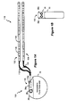
- the IPG 100 is coupled to electrodes 106 via one or more electrode leads (two such leads 102 and 104 are shown), such that the electrodes 106 form an electrode array 110.
- the electrodes 106 are carried on a flexible body 108, which also houses the individual signal wires 112, 114, coupled to each electrode.
- the signal wires 112 and 114 are connected to the IPG 100 by way of an interface 115, which may be any suitable device that allows the leads 102 and 104 (or a lead extension, not shown) to be removably connected to the IPG 100.
- Interface 115 may comprise, for example, an electro-mechanical connector arrangement including lead connectors 38a and 38b configured to mate with corresponding connectors 119a and 119b on the leads 102 and 104.
- the electrode array 110 is typically implanted along the dura of the spinal cord, and the IPG 100 generates electrical pulses that are delivered through the electrodes 106 to the nerve fibers within the spinal column.
- the IPG 100 itself is then typically implanted somewhat distantly in the buttocks of the patient.
- an IPG 100 typically includes an electronic substrate assembly 14 including a printed circuit board (PCB) 16, along with various electronic components 20, such as microprocessors, integrated circuits, and capacitors, mounted to the PCB 16. Ultimately, the electronic circuitry performs a therapeutic function, such as neurostimulation.
- a feedthrough assembly 24 routes the various electrode signals from the electronic substrate assembly 14 to the lead connectors 38a, 38b, which are in turn coupled to the leads 102 and 104 (see Figs. 1A and 1B ).
- the IPG 100 further comprises a header connector 36, which among other things houses the lead connectors 38a, 38b.
- the IPG 100 can further include a telemetry antenna or coil 96 ( Fig.
- the IPG 100 usually also includes a power source 26, usually a rechargeable battery 26.
- the power source 26 can be recharged transcutaneously by an external charger 12. Specifically, when active during a charging session, the external charger 12 energizes its charging coil 17, which in turn induces a current in the charging coil 18 in the IPG 100. This induced current is rectified and ultimately used to charge the power source 26 through the patient's flesh 25.
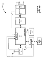
- FIG. 3 A traditional architecture 50 for the circuitry inside of an IPG 100 is shown in Figure 3 .
- Figure 3 depicts the IPG 100's circuitry at a relatively high level sufficient to understand the points this disclosure makes.
- the architecture 50 contains basic circuit blocks for executing various electrical functions in the IPG 100.
- telemetry circuit 62 is coupled to coil 96, and operates to send and receive data to and from an external controller (not shown).
- Charging and battery protection circuitry 64 is similarly coupled to charging coil 18, and intervenes between the power source 26 and the rest of the circuitry. Both of these circuits 62 and 64 are coupled to a microcontroller 60, which as can be noticed is central to the design of the architecture 50.
- Programs and data needed by the microcontroller 60 upon power up are stored in a memory 66, preferably a serial nonvolatile memory, which is coupled to the microcontroller 60 by a serial interface 67.
- Circuitry involved in providing a predictable therapy of stimulation is provided by a digital integrated circuit (IC) 70 and an analog IC 80.
- the digital IC 70 contains stimulation control logic, such as the various timers that are used by the IPG's timing channels to provide a stimulation pulse train with a particular timing.
- the analog IC 80 receives data from the digital IC 70 via a serial link, where such data is converted to analog signals by a digital-to-analog converter (DAC) 82, which in turn ultimately provides the stimulus to the electrodes (E1 ... EN).
- DAC digital-to-analog converter
- an analog-to-digital (A/D) converter 74 is used to inform the microcontroller 60 of various analog voltages being produced or monitored on the analog IC 80, such as various reference voltages, the stimulation compliance voltage, etc., and within the charging 64 and telemetry 62 blocks, although shown as integrated with the microcontroller 60, the A/D converter 74 could also be a discrete component outside of the microcontroller 60.
- the microcontroller 60, the digital IC 70, and the analog IC 80 comprise discrete ICs each comprising one of the components 20 on the IPG's printed circuit board 16 (see Fig. 1 ).
- Other functional blocks in the architecture 50 might comprise other components 20, which might not be integrated but rather formed at least in part of discrete components.
- inter-connectivity adds to the expense of the IPG 100 and its complexity. Moreover, it also makes it difficult to adapt a particular architecture to desired changes and/or newer IPG revisions. For example, the changing of one of the functional blocks may require significant corresponding changes in other functional blocks, making upgrades or revisions expensive.
- IPGs are preferably as small as possible to make the implant as unobtrusive as possible for the patient.
- the architecture 50 of Figure 3 is further problematic because of its requirement of separate IC used for the microcontroller 60, the digital IC 70, and the analog IC 80 (and possibly other components). Having numerous components generally negatively impacts the reliability of the circuit, and increases power consumption, generally a big concern for a power-limited IPG.
- This disclosure presents a solution to this problem in the art of implantable medical devices via an improved IPG architecture.
- the following aspects are preferred embodiments of the invention.
- FIGS 1A and 1B show an implantable pulse generator (IPG), and the manner in which an electrode array is coupled to the IPG in accordance with the prior art.
- IPG implantable pulse generator
- FIG. 2 shows the IPG in relation to an external charger in accordance with the prior art.
- FIG. 3 shows the architecture of the circuitry within the IPG in accordance with the prior art.
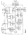
- Figure 4 shows an improved architecture for an IPG incorporating a centralized bus operating with the various functional blocks in accordance with a communication protocol.
- Figure 5 shows the various signal on the centralized bus of Figure 4 and indicates the communication protocol used on the bus.
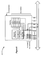
- Figure 6 shows the basic structure of the bus interface circuitry used by each functional block communicating with the centralized bus of Figure 4 .
- Figure 7 shows how the improved architecture of Figure 4 easily provides for additional memory or controller resources outside of an IPG IC built in accordance with the architecture of Figure 4 .
- Figure 8 shows various registers useful in sharing control between an external controller and a controller internal to an IPG IC built in accordance with the architecture of Figure 4 .
- Figure 9 shows the circuitry useful for sharing control between the external and internal controller of Figure 8 .
- Figure 10 shows a flow chart discussing the operation of the circuitry of Figure 9 .
- an implantable medical device such as an implantable pulse generator (IPG)
- the various functional blocks for the IPG are incorporated into a single integrated circuit (IC).
- Each of the functional blocks communicate with each other, and with other off-chip devices if necessary, via a centralized bus governed by a communication protocol.
- each circuit block includes bus interface circuitry adherent with that protocol. Because each block complies with the protocol, any given block can easily be modified or upgraded without affecting the design of the other blocks, facilitating debugging and upgrading of the IPG circuitry.
- the centralized bus can be taken off the integrated circuit, extra circuitry can easily be added off chip to modify or add functionality to the IPG without the need for a major redesign of the main IPG IC.
- Figure 4 shows one example of the improved IPG architecture 150.
- most of the functional blocks in Figure 4 correspond to circuit blocks of Figure 3 , and thus perform similar functions in the new architecture 150.
- all of the functional blocks in the improved architecture 150 are coupled to a centralized bus 190.
- the centralized bus 190 is a parallel bus containing a plurality of multiplexed address and data lines operating in parallel.
- bus 190 can comprise a serial bus as well.
- each of the illustrated functional blocks are integrated within a single integrated circuit (IC) 200.
- the IPG IC 200 as illustrated contains both analog and digital signals, the IC 200 would comprise a mixed mode chip. However, it is not strictly necessary that the architecture 150 be realized on a single IC 200 as shown. Moreover, it should be understood that certain other circuitry components within the IPG 100 (such as the data and charging coils 96 and 18, the power source 26, and external memory 66, etc.) would logically reside outside of the IC 200.
- Each of the various functional blocks in the improved IPG architecture 150 communicate with the centralized bus 190 via bus interface circuitry 215, which will be discussed in further detail later.
- bus interface circuitry 215 which will be discussed in further detail later.
- all other non-bus-based communications between the functional blocks are kept to a minimum, but some such communications are beneficial.
- various interrupts (INT1, INT2, ...) communicate directly with an interrupt controller 173, which allows their issuance to be immediately recognized without the potential delays involved in protocol-based communication through the centralized bus 190.
- INT2 can inform the interrupt controller 173 if the power source 26 is charged to a dangerous level, so that operation of the IC 200 might be temporarily curtailed if necessary.
- an analog bus 192 is used to send various analog signals to a A/D block 74 where such voltages can be digitized and made available to other functional blocks via the centralized bus 190 as needed.
- each functional block contains set up and status registers (not shown).
- the controller 160 upon initialization, writes to the set up registers to configure and enable each functional block.
- the status registers are then set by each functional block and read by the controller 160 to query for status and other results.
- the bus interface circuitry 215 of the internal controller 160 is somewhat unique and, for example, contains driver circuitry 216 for the control signals used by the communications protocol (e.g., ALE, W/E, and R/E) which would be lacking in the bus interface circuitry 215 of other functional blocks within the IC 200.
- the communications protocol e.g., ALE, W/E, and R/E
- the IC 200 contains several external terminals 202 (e.g., pins, solder bumps, etc.), such as those necessary to connect the power source 26, to connect the coils 18, 96, to connect the external memory 66, and to connect the stimulation electrodes.
- other external terminals 202 are dedicated to the various signals that comprise the centralized bus 190 to allow this bus to communicate with other devices outside of the IC 200, as will be explained in more detail later.
- the centralized bus 190 comprises a clock signal (CLK) for synchronization, time-multiplexed address and data signals (A/Dx); an address latch enable signal (ALE); an active-low write enable signal (*W/E), and an active-low read enable signal (*R/E).
- CLK clock signal
- A/Dx time-multiplexed address and data signals
- ALE address latch enable signal
- *W/E active-low write enable signal
- R/E active-low read enable signal
- the centralized bus 90 may comprise sixteen address/data signals, but of course this number can change depending on system requirements.
- communications in an IPG system such as one including the IC 200 of Figure 4 can operate relatively slowly compared to other computerized systems.
- the frequency for the clock signal, CLK can be in the range of 32kHZ to 1MHz.
- Such a frequency is generally slow for a computerized protocol, but is suitably fast compared to operation of the IPG, which typically provide stimulation pulses on the order of tens of microseconds to milliseconds.
- the protocol uses a fairly simple address-before-data scheme in which an address is followed by pertinent data for that address, etc.
- the address latch enable signal (ALE) is active only upon the issuance of an address, which allows the address to be latched upon the rising edge of the clock. Whether the data corresponding to a particular address is to be written or read depends on the assertion of the write and read enable signals (*W/E; *R/E).
- this protocol is merely exemplary and other protocols and formats could be use for communication on the centralized bus 190.
- the nature of the protocol of Figure 5 means that all functional blocks coupled to the centralized bus 190 must be designated an address, or more likely, a range of addresses.
- the address for a data register holding the value for the compliance voltage might be ADDR[3401] while the address for a bandgap reference voltage might be ADDR[3402];
- the address for the magnitude of stimulation to be provided by electrode E6 in stimulation circuitry block 175) may be ADDR[7655], while the duration of that pulse may be stored at ADDR[7655], etc.
- each block contains bus interface circuitry 215, which is shown in Figure 6 .
- bus interface circuitry 215 One skilled in the art will well understand the operation of bus interface circuitry 215, and so it is explained at a general level.
- one or more addresses may be associated with each functional block, such as ADDR[1]-[5] in the simple example of Figure 6 .
- each block decodes those addresses to determine a match, i.e., to determine if the address corresponds to one of the addresses pointing to that block.
- bus drivers in the case of a read
- bus receivers in the case of a write
- bus interface circuitry 215 allowing each functional block to communicate using the protocol established for the bus 190, it now becomes a relatively simple endeavor to make changes to the various functional blocks to fix circuit errors, and/or to upgrade the IC 200 for use in next-generation IPGs. This is because each of the blocks' circuitry can be changed without worries that such changes will necessitate other changes in related blocks, or otherwise perturb the operation of other blocks. Functional blocks can be independently designed and verified in parallel, saving time and hassle during the design process.
- Another advantage of the improved architecture 150 is the ability to easily modify or add functionality to the IPG 100 outside of the IC 200. For example, future improvements may require the IPG to store more data than is otherwise available in the on-chip memory 177 or the off-chip memory 66 (see Fig. 4 ). In such a case, and if the centralized-bus architecture 150 is used within the IC 200, the bus 190 may be extended outside of the IC 200 as shown in Figure 7 , and more memory 300 (preferably, nonvolatile memory) added. This is of great benefit, because it allows the IPG circuitry to be upgraded without to need to redesign the IC 200 and/or some of its functional blocks.
- the capacity of the system can be effectively doubled by the addition of another IC 200' similarly constructed to the first IC 200.
- the capacity of the IPG can be increased by simply "daisy chaining" a plurality of stimulation ICs together.
- the IPG system can utilize both controllers 160 in both of the ICs 200 and 200', although this requires arbitration between the two controllers to prevent potential conflicts, a subject discussed below with reference to Figures 8-10 .
- an external microcontroller 240 is used to supplant or augment the internal controller 160 resident within the IC 200.
- the external microcontroller 240 could comprise the internal controller 160 of an additional IC 200', a point discussed above).
- the ability to control the IPG via an external controller means that the programming for the IPG can be changed without changes to the IC 200 or the various functional blocks.
- the internal controller 160 is provided with additional functionality as illustrated in Figures 8 and 9 .
- CSB controller select bit
- CSB can comprise a discrete communication signal generally outside of the scope of the centralized bus 190, which due to its discrete nature can be a preferable implementation as a faster and safer method of arbitration between the two controllers 160 and 240.
- the controller select bit can comprise data sent via the bus 190 using the bus 190's protocol.
- the CSB data could be viewed as a control "token" which is passed between the internal controller 160 and the external microcontroller 240 via the bus 190.
- Such a purely bus-based method for arbitration between the controllers is easily implemented. However, because it is easier to illustrate the passage of control between the two controllers 160 and 240 using a discrete non-bus based signal approach, that approach is illustrated below and in the figures.
- the internal controller 160 is designed with two registers, a command register 220 and a command owner register 230, shown in detail in Figure 8 .
- the command register 220 is a standard feature of many controllers, and simply comprises a binary representation of the various commands the IPG can execute. In the example shown, because the command register 220 is eight bits long, the IPG 100 is capable of processing 256 (2 ⁇ 8) different commands.
- the command owner register 230 is comprised of as many bits as there are relevant commands (in this example, 256), with each bit in the register denoting whether a particular command is to be handled by the internal controller 160 or the external microcontroller 240.
- command owner register 230 As shown, if particular bit in the command owner register 230 is a '0', the corresponding command is to be executed by the internal controller 160; and if a '1,' the external microcontroller 240 will execute the command.
- the 256-bit command owner register 230 reads '1010000 ... 0001," commands 256, 254, and 1 (CMD256, CMD254, and CMD1) would be executed by the external microcontroller 240, with all other commands executed by the internal controller 160.
- command register 220 and command owner register 230 to issue a controller select bit (CSB) 245 is illustrated in Figure 9 .
- CSB controller select bit
- the command owner register 230 is loaded with default values from memory (internal memory 177, serial external memory 66, etc.). Normally, the default values of the various command owner bits in the command owner register 230 would be all '0's, denoting that at least initially all commands are to be executed by the internal controller 160. Thereafter, at some point during operation, the command register 220 is loaded with a command at its address (ADDR[CMD]). The command is decoded (demultiplexed) as explained above, and the corresponding command owner bit is issued as the controller select bit (CSB) 245. The CSB 245 is also stored in the controller enable register 250 at its address (ADDR[CER]), which may comprise a single bit, as shown in Figure 9 . The CSB 245 is also sent to the external controller 240.
- memory internal memory 177, serial external memory 66, etc.
- the command register 220 is loaded with a command at its address (ADDR[CMD]).
- the command is decoded (demultiplex
- the internal controller bus drivers 212 are enabled by the stored controller enable register bit 250 (an active low signal).
- the command i.e., its command
- the arbitration logic 246 With the command executed by the external microcontroller 240, the remaining steps illustrated in Figure 10 are directed to returning control back to the internal controller 160 prior to the receipt of a next command.
- the arbitration logic 246 now writes a '0' in the controller enable register 250, which can be accessed via the bus 190 at its address ADDR[CER]. This in turn once again enables the bus drivers 212 for the internal controller 160.
- the arbitration logic 246 disables the bus drivers 242 for the external controller 240. This restores the system to its initial state in which the internal controller 160 assumes control by default, at which point the system awaits its next command, and the method repeats, etc.
Landscapes
- Health & Medical Sciences (AREA)
- Animal Behavior & Ethology (AREA)
- Public Health (AREA)
- Engineering & Computer Science (AREA)
- Biomedical Technology (AREA)
- Nuclear Medicine, Radiotherapy & Molecular Imaging (AREA)
- Radiology & Medical Imaging (AREA)
- Veterinary Medicine (AREA)
- Life Sciences & Earth Sciences (AREA)
- General Health & Medical Sciences (AREA)
- Neurology (AREA)
- Neurosurgery (AREA)
- Orthopedic Medicine & Surgery (AREA)
- Cardiology (AREA)
- Heart & Thoracic Surgery (AREA)
- Pain & Pain Management (AREA)
- Electrotherapy Devices (AREA)
Applications Claiming Priority (2)
| Application Number | Priority Date | Filing Date | Title |
|---|---|---|---|
| US11/767,636 US8649858B2 (en) | 2007-06-25 | 2007-06-25 | Architectures for an implantable medical device system |
| EP08744940A EP2164565A1 (fr) | 2007-06-25 | 2008-04-02 | Architecture améliorée d'un système de dispositif médical implantable |
Related Parent Applications (1)
| Application Number | Title | Priority Date | Filing Date |
|---|---|---|---|
| EP08744940.1 Division | 2008-04-02 |
Publications (1)
| Publication Number | Publication Date |
|---|---|
| EP2316526A1 true EP2316526A1 (fr) | 2011-05-04 |
Family
ID=39455093
Family Applications (2)
| Application Number | Title | Priority Date | Filing Date |
|---|---|---|---|
| EP10189975A Withdrawn EP2316526A1 (fr) | 2007-06-25 | 2008-04-02 | Architecture améliorée pour système de dispositif médical implantable |
| EP08744940A Withdrawn EP2164565A1 (fr) | 2007-06-25 | 2008-04-02 | Architecture améliorée d'un système de dispositif médical implantable |
Family Applications After (1)
| Application Number | Title | Priority Date | Filing Date |
|---|---|---|---|
| EP08744940A Withdrawn EP2164565A1 (fr) | 2007-06-25 | 2008-04-02 | Architecture améliorée d'un système de dispositif médical implantable |
Country Status (5)
| Country | Link |
|---|---|
| US (3) | US8649858B2 (fr) |
| EP (2) | EP2316526A1 (fr) |
| JP (2) | JP2010531207A (fr) |
| CA (1) | CA2687183C (fr) |
| WO (1) | WO2009002579A1 (fr) |
Families Citing this family (71)
| Publication number | Priority date | Publication date | Assignee | Title |
|---|---|---|---|---|
| JP5349682B2 (ja) * | 2009-04-29 | 2013-11-20 | アルカテル−ルーセント | Mbsfn内のmbmsサービスを多重化する方法、bm−sc、および基地局 |
| US8321029B2 (en) | 2009-09-18 | 2012-11-27 | Boston Scientific Neuromodulation Corporation | External charger usable with an implantable medical device having a programmable or time-varying temperature set point |
| WO2012027791A1 (fr) | 2010-08-31 | 2012-03-08 | National Ict Australia Ltd | Systèmes d'implants répartis |
| AU2011313977B2 (en) * | 2010-10-13 | 2015-07-02 | Boston Scientific Neuromodulation Corporation | Architectures for an implantable medical device system having daisy-chained electrode-drive integrated circuits |
| US8768453B2 (en) * | 2010-10-13 | 2014-07-01 | Boston Scientific Neuromodulation Corporation | Monitoring electrode voltages in an implantable medical device system having daisy-chained electrode-driver integrated circuits |
| US8509908B2 (en) | 2011-04-20 | 2013-08-13 | Cochlear Limited | Inter-chip communications for implantable stimulating devices |
| WO2012155185A1 (fr) | 2011-05-13 | 2012-11-22 | National Ict Australia Ltd | Méthode et appareil de mesure de la réponse neuronale |
| US10588524B2 (en) | 2011-05-13 | 2020-03-17 | Saluda Medical Pty Ltd | Method and apparatus for measurement of neural response |
| WO2012155189A1 (fr) | 2011-05-13 | 2012-11-22 | National Ict Australia Ltd | Méthode et appareil d'estimation du recrutement neuronal-f |
| JP6096759B2 (ja) | 2011-05-13 | 2017-03-15 | サルーダ・メディカル・ピーティーワイ・リミテッド | 神経応答の測定のための方法および装置 |
| US9872990B2 (en) | 2011-05-13 | 2018-01-23 | Saluda Medical Pty Limited | Method and apparatus for application of a neural stimulus |
| WO2013048463A1 (fr) * | 2011-09-30 | 2013-04-04 | Intel Corporation | Système et procédé de saisie de données sur un dispositif électronique portable |
| US20130184794A1 (en) | 2012-01-16 | 2013-07-18 | Boston Scientific Neuromodulation Corporation | Architectures for an Implantable Stimulator Device Having a Plurality of Electrode Driver Integrated Circuits with Shorted Electrode Outputs |
| US9186520B2 (en) | 2012-01-16 | 2015-11-17 | Boston Scientific Neuromodulation Corporation | Automatic on-off charger for an implantable medical device |
| US9037241B2 (en) | 2012-02-10 | 2015-05-19 | Boston Scientific Neuromodulation Corporation | Power architecture for an implantable medical device having a non-rechargeable battery |
| US9352162B2 (en) | 2012-02-10 | 2016-05-31 | Boston Scientific Neuromodulation Corporation | Power architecture for an implantable medical device having a non-rechargeable battery |
| JP6070828B2 (ja) | 2012-04-27 | 2017-02-01 | ボストン サイエンティフィック ニューロモデュレイション コーポレイション | 埋込可能刺激デバイスでパルスを生成するためのタイミングチャネル回路 |
| US9174051B2 (en) | 2012-04-29 | 2015-11-03 | Boston Scientific Neuromodulation Corporation | Real time compliance voltage generation for an implantable stimulator |
| US9314632B2 (en) | 2012-05-17 | 2016-04-19 | Boston Scientific Neuromodulation Corporation | Pulse-by-pulse compliance voltage generation for an implantable stimulator |
| AU2013344311B2 (en) | 2012-11-06 | 2017-11-30 | Saluda Medical Pty Ltd | Method and system for controlling electrical conditions of tissue |
| ES2836792T3 (es) | 2012-11-06 | 2021-06-28 | Saluda Medical Pty Ltd | Sistema para controlar las condiciones eléctricas de un tejido |
| US9364673B2 (en) | 2013-10-16 | 2016-06-14 | Boston Scientific Neuromodulation Corporation | Power supply disconnect current measurement for an implantable medical device |
| AU2014351064B2 (en) | 2013-11-15 | 2019-07-04 | Closed Loop Medical Pty Ltd | Monitoring brain neural potentials |
| CA2929874C (fr) | 2013-11-22 | 2023-06-13 | Saluda Medical Pty Ltd | Procede et dispositif de detection d'une reponse neurale dans une mesure neurale |
| US10004911B2 (en) | 2014-01-16 | 2018-06-26 | Boston Scientific Neuromodulation Corporation | Circuitry for charging a depleted battery in an implantable medical device without passive trickle charging |
| US9707395B2 (en) | 2014-01-16 | 2017-07-18 | Boston Scientific Neuromodulation Corporation | Circuitry for charging a battery in an implantable medical device in accordance with historical parameters impacting battery capacity |
| US9446244B2 (en) | 2014-01-16 | 2016-09-20 | Boston Scientific Neuromodulation Corporation | Determining and forecasting end of life for an implantable medical device having a rechargeable battery |
| WO2015143509A1 (fr) | 2014-03-28 | 2015-10-01 | Saluda Medical Pty Ltd | Évaluation de l'état neuronal à partir de potentiels d'action |
| WO2015168735A1 (fr) | 2014-05-05 | 2015-11-12 | Saluda Medical Pty Ltd | Mesure neuronale amelioree |
| DK3171929T3 (da) | 2014-07-25 | 2021-05-25 | Saluda Medical Pty Ltd | Dosering til nervestimulation |
| AU2015349614B2 (en) | 2014-11-17 | 2020-10-22 | Saluda Medical Pty Ltd | Method and device for detecting a neural response in neural measurements |
| EP3218046B1 (fr) | 2014-12-11 | 2024-04-17 | Saluda Medical Pty Ltd | Dispositif et programme informatique pour la commande de rétroaction de stimulation neuronale |
| US10588698B2 (en) | 2014-12-11 | 2020-03-17 | Saluda Medical Pty Ltd | Implantable electrode positioning |
| AU2016208972B2 (en) | 2015-01-19 | 2021-06-24 | Saluda Medical Pty Ltd | Method and device for neural implant communication |
| WO2016161484A2 (fr) | 2015-04-09 | 2016-10-13 | Saluda Medical Pty Ltd | Estimation de distance électrode-nerf |
| CA2983336C (fr) | 2015-05-31 | 2024-05-28 | Saluda Medical Pty Ltd | Surveillance de l'activite neurale du cerveau |
| WO2016191807A1 (fr) | 2015-05-31 | 2016-12-08 | Saluda Medical Pty Ltd | Fixation d'électrode de neurostimulateur cérébral |
| JP7204325B2 (ja) | 2015-06-01 | 2023-01-16 | クローズド・ループ・メディカル・ピーティーワイ・リミテッド | 運動線維ニューロモジュレーション |
| US11191966B2 (en) | 2016-04-05 | 2021-12-07 | Saluda Medical Pty Ltd | Feedback control of neuromodulation |
| EP3474747B1 (fr) | 2016-06-24 | 2026-04-22 | Saluda Medical Pty Ltd | Stimulation neurale pour un artéfact réduit |
| US10589090B2 (en) | 2016-09-10 | 2020-03-17 | Boston Scientific Neuromodulation Corporation | Implantable stimulator device with magnetic field sensing circuit |
| US11040192B2 (en) | 2016-09-10 | 2021-06-22 | Boston Scientific Neuromodulation Corporation | Current generation architecture for an implantable medical device |
| US10549091B2 (en) | 2016-09-10 | 2020-02-04 | Boston Scientific Neuromodulation Corporation | Use models for a current generation architecture for an implantable medical device |
| US10525252B2 (en) | 2016-09-10 | 2020-01-07 | Boston Scientific Neuromodulation Corporation | Compliance voltage monitoring and adjustment in an implantable medical device |
| US10632300B2 (en) | 2016-09-10 | 2020-04-28 | Boston Scientific Neuromodulation Corporation | Measurement circuitry for measuring analog values in an implantable pulse generator |
| US10576265B2 (en) | 2016-09-10 | 2020-03-03 | Boston Scientific Neuromodulation Corporation | Pulse definition circuitry for creating stimulation waveforms in an implantable pulse generator |
| US10716932B2 (en) | 2016-09-10 | 2020-07-21 | Boston Scientific Neuromodulation Corporation | Pulse definition circuitry for creating stimulation waveforms in an implantable pulse generator |
| US10786665B2 (en) | 2016-09-10 | 2020-09-29 | Boston Scientific Neuromodulation Corporation | Biasing of a current generation architecture for an implantable medical device |
| US10716937B2 (en) | 2016-09-10 | 2020-07-21 | Boston Scientific Neuromodulation Corporation | Passive charge recovery circuitry for an implantable medical device |
| US10525253B2 (en) | 2016-10-13 | 2020-01-07 | Boston Scientific Neuromodulation Corporation | Current generation architecture for an implantable medical device including controllable slew rate |
| US10819713B2 (en) | 2017-04-24 | 2020-10-27 | Boston Scientific Neuromodulation Corporation | Technique to ensure security for connected implantable medical devices |
| US12090324B2 (en) | 2017-08-11 | 2024-09-17 | Boston Scientific Neuromodulation Corporation | Spinal cord stimulation for dorsal column recruitment or suppression using anodic and cathodic pulses |
| US11844947B2 (en) | 2017-08-11 | 2023-12-19 | Boston Scientific Neuromodulation Corporation | Spinal cord stimulation occurring using monophasic pulses of alternating polarities and passive charge recovery |
| US11083887B2 (en) | 2017-09-12 | 2021-08-10 | Boston Scientific Neuromodulation Corporation | Techniques for sensing incorrect lead connection to an implantable stimulator device |
| US10780285B2 (en) | 2017-09-15 | 2020-09-22 | Boston Scientific Neuromodulation Corporation | Current generation architecture for an implantable stimulator device including distributor circuitry for sending an amplitude-scaled current to digital-to-analog converters at the electrodes |
| AU2018222994B2 (en) | 2017-09-15 | 2019-11-07 | Boston Scientific Neuromodulation Corporation | Current generation architecture for an implantable stimulator device to promote current steering between electrodes |
| EP4434461A3 (fr) | 2018-04-27 | 2025-03-05 | Saluda Medical Pty Ltd | Neurostimulation de nerfs mixtes |
| WO2019209474A1 (fr) | 2018-04-27 | 2019-10-31 | Boston Scientific Neuromodulation Corporation | Stimulation anodique dans un système de stimulateur implantable utilisant des impulsions de stimulation anodique et cathodique asymétriques |
| AU2019260567B2 (en) | 2018-04-27 | 2021-09-23 | Boston Scientific Neuromodulation Corporation | Neurostimulation system for delivering selectivity modes |
| EP3755426B1 (fr) | 2018-05-11 | 2023-08-30 | Boston Scientific Neuromodulation Corporation | Formes d'onde de stimulation à aspects haute et basse fréquence dans un dispositif de stimulation implantable |
| EP3801741B1 (fr) | 2018-06-04 | 2022-07-20 | Boston Scientific Neuromodulation Corporation | Enregistrement de l'exécution de sous-programmes dans un programme de stimulation pour un dispositif de stimulation implantable |
| WO2020005589A1 (fr) | 2018-06-27 | 2020-01-02 | Boston Scientific Neuromodulation Corporation | Modélisation de champ de stimulation dans un dispositif de stimulation implantable |
| US11738198B2 (en) | 2019-05-10 | 2023-08-29 | The Freestate Of Bavaria Represented By The Julius Maximilians-Universität Würzbrg | System to optimize anodic stimulation modes |
| US12383745B2 (en) | 2019-09-06 | 2025-08-12 | Boston Scientific Neuromodulation Corporation | Management of compliance voltage for a stimulator device |
| CA3167019C (fr) | 2020-03-03 | 2025-08-26 | Boston Scientific Neuromodulation Corporation | Circuit convertisseur numerique-analogique pour un dispositif de stimulation ayant un reglage d'amplitude non lineaire |
| WO2021194684A1 (fr) | 2020-03-26 | 2021-09-30 | Boston Scientific Neuromodulation Corporation | Interface graphique utilisateur pour ajuster une intensité de courant dans un dispositif de stimulation |
| AU2021353091B2 (en) | 2020-09-30 | 2024-06-06 | Boston Scientific Neuromodulation Corporation | Pairing of external communication devices with an implantable medical device via a patient remote controller |
| CA3197467A1 (fr) | 2020-09-30 | 2022-04-07 | Boston Scientific Neuromodulation Corporation | Ajustement d'un intervalle d'annonce dans des communications entre un dispositif medical implantable et un dispositif externe |
| EP4623988A3 (fr) | 2020-09-30 | 2025-11-05 | Boston Scientific Neuromodulation Corporation | Programmation de modes d'appairage et irm dans un système de dispositif médical implantable |
| US12527959B2 (en) | 2020-11-20 | 2026-01-20 | Boston Scientific Neuromodulation Corporation | Compliance voltage monitoring and adjustment in an implantable medical device using low side sensing |
| EP4284487B1 (fr) | 2021-04-06 | 2025-07-02 | Boston Scientific Neuromodulation Corporation | Architecture de génération de courant pour un dispositif stimulateur implantable |
Citations (6)
| Publication number | Priority date | Publication date | Assignee | Title |
|---|---|---|---|---|
| US5876425A (en) * | 1989-09-22 | 1999-03-02 | Advanced Bionics Corporation | Power control loop for implantable tissue stimulator |
| US20020052633A1 (en) * | 1997-07-30 | 2002-05-02 | Intermedics Inc. | Stackable microelectronic components with self-addressing scheme |
| US6516227B1 (en) | 1999-07-27 | 2003-02-04 | Advanced Bionics Corporation | Rechargeable spinal cord stimulator system |
| US6754533B1 (en) * | 2000-06-16 | 2004-06-22 | Medtronic, Inc. | Implantable medical device configured for diagnostic emulation |
| WO2005061044A2 (fr) * | 2003-12-11 | 2005-07-07 | Medtronic, Inc. | Systeme de communication avec un dispositif medical implantable dote d'une polarisation par courant pulse |
| WO2006029090A2 (fr) * | 2004-09-02 | 2006-03-16 | Proteus Biomedical, Inc. | Methodes et appareil d'activation et de surveillance de tissus |
Family Cites Families (33)
| Publication number | Priority date | Publication date | Assignee | Title |
|---|---|---|---|---|
| US4388927A (en) * | 1979-12-13 | 1983-06-21 | American Hospital Supply Corporation | Programmable digital cardiac pacer |
| US4562841A (en) * | 1982-08-05 | 1986-01-07 | Cardiac Pacemakers, Inc. | Programmable multi-mode cardiac pacemaker |
| US5603726A (en) * | 1989-09-22 | 1997-02-18 | Alfred E. Mann Foundation For Scientific Research | Multichannel cochlear implant system including wearable speech processor |
| US5188106A (en) * | 1991-03-08 | 1993-02-23 | Telectronics Pacing Systems, Inc. | Method and apparatus for chronically monitoring the hemodynamic state of a patient using doppler ultrasound |
| US5215083A (en) * | 1991-10-07 | 1993-06-01 | Telectronics Pacing Systems, Inc. | Apparatus and method for arrhythmia induction in arrhythmia control system |
| US5330507A (en) * | 1992-04-24 | 1994-07-19 | Medtronic, Inc. | Implantable electrical vagal stimulation for prevention or interruption of life threatening arrhythmias |
| SE9202521D0 (sv) | 1992-09-02 | 1992-09-02 | Siemens Elema Ab | Anordning foer stimulering av levande vaevnad |
| US5464435A (en) * | 1994-02-03 | 1995-11-07 | Medtronic, Inc. | Parallel processors in implantable medical device |
| EP0688577A1 (fr) | 1994-06-24 | 1995-12-27 | Pacesetter AB | Dispositif de traitement de tachyarythmie auriculaire |
| EP0688579B1 (fr) * | 1994-06-24 | 2001-08-22 | St. Jude Medical AB | Dispositif de thérapie cardiaque |
| SE9503257D0 (sv) * | 1995-09-20 | 1995-09-20 | Pacesetter Ab | Implanterbar hjärtdefibrillator |
| US5735887A (en) * | 1996-12-10 | 1998-04-07 | Exonix Corporation | Closed-loop, RF-coupled implanted medical device |
| US5941906A (en) * | 1997-10-15 | 1999-08-24 | Medtronic, Inc. | Implantable, modular tissue stimulator |
| US6317633B1 (en) * | 1999-01-19 | 2001-11-13 | Medtronic, Inc. | Implantable lead functional status monitor and method |
| US6648821B2 (en) * | 2000-01-21 | 2003-11-18 | Medtronic Minimed, Inc. | Microprocessor controlled ambulatory medical apparatus with hand held communication device |
| JP4703083B2 (ja) * | 2000-01-21 | 2011-06-15 | メドトロニック ミニメド インコーポレイテッド | 医療システム |
| US6738670B1 (en) * | 2000-06-19 | 2004-05-18 | Medtronic, Inc. | Implantable medical device telemetry processor |
| JP4177102B2 (ja) * | 2000-10-26 | 2008-11-05 | メドトロニック・インコーポレーテッド | 心機能及び心効率を改善するための装置 |
| US6731985B2 (en) * | 2001-10-16 | 2004-05-04 | Pacesetter, Inc. | Implantable cardiac stimulation system and method for automatic capture verification calibration |
| US7010344B2 (en) * | 2002-04-26 | 2006-03-07 | Medtronic, Inc. | Method and apparatus for delaying a ventricular tachycardia therapy |
| US7013178B2 (en) * | 2002-09-25 | 2006-03-14 | Medtronic, Inc. | Implantable medical device communication system |
| US7277757B2 (en) * | 2002-10-31 | 2007-10-02 | Medtronic, Inc. | Respiratory nerve stimulation |
| CA2441658C (fr) * | 2003-09-19 | 2011-01-11 | Brian A. Cruson | Dispositif et methode de compostage |
| US20060029090A1 (en) * | 2004-08-04 | 2006-02-09 | Angelo Bione | Method and system for distributing wireless communication signals in an HFC network |
| US7715912B2 (en) * | 2005-04-13 | 2010-05-11 | Intelect Medical, Inc. | System and method for providing a waveform for stimulating biological tissue |
| US7881786B2 (en) * | 2005-04-29 | 2011-02-01 | Medtronic, Inc. | Suppression of high rate pacing for reducing myocardial ischemic irritability |
| US20070027485A1 (en) * | 2005-07-29 | 2007-02-01 | Kallmyer Todd A | Implantable medical device bus system and method |
| US8827904B2 (en) | 2005-08-31 | 2014-09-09 | Medtronic, Inc. | Automatic parameter status on an implantable medical device system |
| DE102005051411B4 (de) | 2005-10-27 | 2007-07-19 | Atmel Germany Gmbh | Bussystem für integrierten Schaltkreis |
| US7444181B2 (en) * | 2005-12-14 | 2008-10-28 | Boston Scientific Neuromodulation Corporation | Techniques for sensing and adjusting a compliance voltage in an implantable stimulator device |
| US8290593B2 (en) * | 2008-10-31 | 2012-10-16 | Medtronic, Inc. | Implantable medical device including a plurality of lead connection assemblies |
| US8200335B2 (en) * | 2008-10-31 | 2012-06-12 | Medtronic, Inc. | Implantable medical device lead connection assembly |
| US20130184794A1 (en) * | 2012-01-16 | 2013-07-18 | Boston Scientific Neuromodulation Corporation | Architectures for an Implantable Stimulator Device Having a Plurality of Electrode Driver Integrated Circuits with Shorted Electrode Outputs |
-
2007
- 2007-06-25 US US11/767,636 patent/US8649858B2/en not_active Expired - Fee Related
-
2008
- 2008-04-02 WO PCT/US2008/059134 patent/WO2009002579A1/fr not_active Ceased
- 2008-04-02 EP EP10189975A patent/EP2316526A1/fr not_active Withdrawn
- 2008-04-02 EP EP08744940A patent/EP2164565A1/fr not_active Withdrawn
- 2008-04-02 CA CA2687183A patent/CA2687183C/fr not_active Expired - Fee Related
- 2008-04-02 JP JP2010514892A patent/JP2010531207A/ja active Pending
-
2010
- 2010-09-16 US US12/883,797 patent/US20110015705A1/en not_active Abandoned
-
2012
- 2012-05-21 JP JP2012115921A patent/JP2012152606A/ja active Pending
-
2015
- 2015-12-07 US US14/961,649 patent/US20160082260A1/en not_active Abandoned
Patent Citations (6)
| Publication number | Priority date | Publication date | Assignee | Title |
|---|---|---|---|---|
| US5876425A (en) * | 1989-09-22 | 1999-03-02 | Advanced Bionics Corporation | Power control loop for implantable tissue stimulator |
| US20020052633A1 (en) * | 1997-07-30 | 2002-05-02 | Intermedics Inc. | Stackable microelectronic components with self-addressing scheme |
| US6516227B1 (en) | 1999-07-27 | 2003-02-04 | Advanced Bionics Corporation | Rechargeable spinal cord stimulator system |
| US6754533B1 (en) * | 2000-06-16 | 2004-06-22 | Medtronic, Inc. | Implantable medical device configured for diagnostic emulation |
| WO2005061044A2 (fr) * | 2003-12-11 | 2005-07-07 | Medtronic, Inc. | Systeme de communication avec un dispositif medical implantable dote d'une polarisation par courant pulse |
| WO2006029090A2 (fr) * | 2004-09-02 | 2006-03-16 | Proteus Biomedical, Inc. | Methodes et appareil d'activation et de surveillance de tissus |
Also Published As
| Publication number | Publication date |
|---|---|
| CA2687183C (fr) | 2015-03-31 |
| US20110015705A1 (en) | 2011-01-20 |
| EP2164565A1 (fr) | 2010-03-24 |
| JP2010531207A (ja) | 2010-09-24 |
| US20080319497A1 (en) | 2008-12-25 |
| CA2687183A1 (fr) | 2008-12-31 |
| WO2009002579A1 (fr) | 2008-12-31 |
| US20160082260A1 (en) | 2016-03-24 |
| JP2012152606A (ja) | 2012-08-16 |
| US8649858B2 (en) | 2014-02-11 |
Similar Documents
| Publication | Publication Date | Title |
|---|---|---|
| CA2687183C (fr) | Architecture amelioree d'un systeme de dispositif medical implantable | |
| US9962551B2 (en) | Monitoring electrode voltages in an implantable medical device system having daisy-chained electrode-driver integrated circuits | |
| JP5676000B2 (ja) | デイジーチェーン電極ドライバ集積回路を有する埋め込み型医療装置システムのためのアーキテクチャ | |
| AU2013209855B2 (en) | Architectures for an implantable stimulator device having a plurality of electrode driver integrated circuits with shorted electrode outputs | |
| AU2015227500B2 (en) | Monitoring electrode voltages in an implantable medical device system having daisy-chained electrode-driver integrated circuits | |
| AU2015203779A1 (en) | Architectures for an Implantable Medical Device System Having Daisy-Chained Electrode-Driver Integrated Circuits |
Legal Events
| Date | Code | Title | Description |
|---|---|---|---|
| PUAI | Public reference made under article 153(3) epc to a published international application that has entered the european phase |
Free format text: ORIGINAL CODE: 0009012 |
|
| AC | Divisional application: reference to earlier application |
Ref document number: 2164565 Country of ref document: EP Kind code of ref document: P |
|
| AK | Designated contracting states |
Kind code of ref document: A1 Designated state(s): AT BE BG CH CY CZ DE DK EE ES FI FR GB GR HR HU IE IS IT LI LT LU LV MC MT NL NO PL PT RO SE SI SK TR |
|
| RIN1 | Information on inventor provided before grant (corrected) |
Inventor name: MARNFELDT, GORAN N. Inventor name: NIMMAGADDA, KIRAN Inventor name: FELDMAN, EMANUEL Inventor name: PARRAMON, JORDI Inventor name: AGHASSIAN, DANIEL Inventor name: GRIFFITH, PAUL J. Inventor name: SHI, JESS W. |
|
| 17P | Request for examination filed |
Effective date: 20110608 |
|
| STAA | Information on the status of an ep patent application or granted ep patent |
Free format text: STATUS: THE APPLICATION HAS BEEN WITHDRAWN |
|
| 18W | Application withdrawn |
Effective date: 20170314 |