EP2317008B1 - Procédé et dispositif d'ouverture d'un interstice de pressage - Google Patents
Procédé et dispositif d'ouverture d'un interstice de pressage Download PDFInfo
- Publication number
- EP2317008B1 EP2317008B1 EP20100176729 EP10176729A EP2317008B1 EP 2317008 B1 EP2317008 B1 EP 2317008B1 EP 20100176729 EP20100176729 EP 20100176729 EP 10176729 A EP10176729 A EP 10176729A EP 2317008 B1 EP2317008 B1 EP 2317008B1
- Authority
- EP
- European Patent Office
- Prior art keywords
- roll
- belt
- severing
- guide
- nip
- Prior art date
- Legal status (The legal status is an assumption and is not a legal conclusion. Google has not performed a legal analysis and makes no representation as to the accuracy of the status listed.)
- Not-in-force
Links
- 238000000034 method Methods 0.000 title claims description 13
- 230000013011 mating Effects 0.000 claims description 10
- 230000007547 defect Effects 0.000 claims description 2
- 238000000926 separation method Methods 0.000 description 17
- 239000002184 metal Substances 0.000 description 6
- 239000000123 paper Substances 0.000 description 6
- 239000004033 plastic Substances 0.000 description 6
- 238000003490 calendering Methods 0.000 description 4
- 239000000463 material Substances 0.000 description 3
- 230000002093 peripheral effect Effects 0.000 description 3
- 239000000835 fiber Substances 0.000 description 2
- 238000009499 grossing Methods 0.000 description 2
- 238000010438 heat treatment Methods 0.000 description 2
- 230000037303 wrinkles Effects 0.000 description 2
- 101100450350 Danio rerio helz gene Proteins 0.000 description 1
- 101100450352 Mus musculus Helz gene Proteins 0.000 description 1
- 239000004696 Poly ether ether ketone Substances 0.000 description 1
- 229910000831 Steel Inorganic materials 0.000 description 1
- 239000004809 Teflon Substances 0.000 description 1
- 229920006362 Teflon® Polymers 0.000 description 1
- 239000004760 aramid Substances 0.000 description 1
- 229920003235 aromatic polyamide Polymers 0.000 description 1
- JUPQTSLXMOCDHR-UHFFFAOYSA-N benzene-1,4-diol;bis(4-fluorophenyl)methanone Chemical compound OC1=CC=C(O)C=C1.C1=CC(F)=CC=C1C(=O)C1=CC=C(F)C=C1 JUPQTSLXMOCDHR-UHFFFAOYSA-N 0.000 description 1
- 238000001514 detection method Methods 0.000 description 1
- 238000007598 dipping method Methods 0.000 description 1
- 230000000694 effects Effects 0.000 description 1
- 239000004744 fabric Substances 0.000 description 1
- 239000012530 fluid Substances 0.000 description 1
- 239000011521 glass Substances 0.000 description 1
- 239000000203 mixture Substances 0.000 description 1
- 210000002445 nipple Anatomy 0.000 description 1
- 238000013021 overheating Methods 0.000 description 1
- 235000020825 overweight Nutrition 0.000 description 1
- 229920002530 polyetherether ketone Polymers 0.000 description 1
- 230000001681 protective effect Effects 0.000 description 1
- 239000005060 rubber Substances 0.000 description 1
- 238000007789 sealing Methods 0.000 description 1
- 239000010959 steel Substances 0.000 description 1
- 230000003746 surface roughness Effects 0.000 description 1
Images


Classifications
-
- D—TEXTILES; PAPER
- D21—PAPER-MAKING; PRODUCTION OF CELLULOSE
- D21G—CALENDERS; ACCESSORIES FOR PAPER-MAKING MACHINES
- D21G1/00—Calenders; Smoothing apparatus
- D21G1/002—Opening or closing mechanisms; Regulating the pressure
-
- D—TEXTILES; PAPER
- D21—PAPER-MAKING; PRODUCTION OF CELLULOSE
- D21F—PAPER-MAKING MACHINES; METHODS OF PRODUCING PAPER THEREON
- D21F3/00—Press section of machines for making continuous webs of paper
- D21F3/02—Wet presses
-
- D—TEXTILES; PAPER
- D21—PAPER-MAKING; PRODUCTION OF CELLULOSE
- D21F—PAPER-MAKING MACHINES; METHODS OF PRODUCING PAPER THEREON
- D21F7/00—Other details of machines for making continuous webs of paper
- D21F7/04—Paper-break control devices
-
- D—TEXTILES; PAPER
- D21—PAPER-MAKING; PRODUCTION OF CELLULOSE
- D21G—CALENDERS; ACCESSORIES FOR PAPER-MAKING MACHINES
- D21G5/00—Safety devices
- D21G5/005—Safety devices for calenders
Definitions
- the invention relates to a method for opening a nip treated a fibrous web, which is formed by a circulating over at least two guide rollers belt with a counter roll by the belt over a wrap angle greater than 5 ° conforms to the peripheral surface of the backing roll, wherein the fibrous web by means is monitored by a sensor in front of the nip for tearing or folding and in the event of cracks or creases, the sensor via a control device, a signal to a separation device passes, which moves at least one guide roller during the separation process motor within 0.9 seconds.
- the invention further relates to a device for opening a nip serving for the treatment of a fibrous web, which is formed by a band circulating over at least two guide rollers with a counter-roller by the band conforming to the peripheral surface of the counter-roller over a wrap angle greater than 5 ° the at least one guide roller is displaceably mounted via a separating device, wherein a control is provided which activates the separating device on the basis of a detected via a sensor error of the current fibrous web.
- Nips are the contact surfaces between two circumferential treatment surfaces, between which a fibrous web can be treated.
- calender nipples are used to explain the invention, between which a paper or board web is calendered.
- one of the contact surfaces is provided with a relatively soft surface, and the other treatment surface is formed by a hard, very smooth and often also heatable treatment surface.
- Nips can have very different lengths in the web running direction. This depends, for example, on the type of calender and the pressure under which the treatment surfaces are pressed on one another.
- one of the treatment surfaces is provided with a softer plastic layer, care must be taken that there is never a second heated treatment surface with it direct contact comes, but always a paper web is present in between, which transported away the heat dissipated. In the case of a web break, for example, care must be taken to ensure that the treatment areas separate quickly from each other.
- the first known publication, the EP 1176252 81 refers to a roll calender, which generally has relatively short nip lengths.
- a lower roller which forms a nip with at least one further roller, can be lowered rapidly via a hydraulic cylinder in the event of a fault.
- the lowering operation is skilfully decelerated in order to avoid an abrupt placement of the roller and an associated vibration.
- Such a hydraulic cylinder is activated when, for example, a photocell detects a crack in a fibrous web.
- Modern calenders with very long nips are the band calenders. These are the paper or board web by means of a circulating belt over a larger angle of wrap to a heated Counter roll pressed. In this case, the band is held under belt tension, so that results from the resultant of the curvature and a system pressure to the web. If the band is made of plastic, there is also the danger of overheating of the band in case of web break. On the other hand, if the band is made of metal, that is usually made of a thin sheet steel, its danger of being damaged in the event of folds in the web is very great. The web is retracted in such a calender with rotating counter roll and with applied and circulating belt, which further increases the risk of belt damage.
- the object is achieved in the method by the separation device, the at least one guide roll while maintaining a Bandzugschreib offset such that the tape is spaced after the separation process of the backing roll, wherein the tape is tensioned during or immediately after the separation process via a clamping element.
- the term "motor” is to be understood here as the involvement of all possible drives which can move a roller by electrical, hydraulic or pneumatic means, with rotary motion or stroke. Possibly. are also several such drives necessary.
- the period of 0.9 seconds is an acceptable size at today's web speeds of about 1000 to 2000 m / min, where on the one hand the known in the art sensor for detecting cracks or wrinkles in the web still arranged in a suitable area in front of the calender on the other hand, enough time remains for the control and the motorized separator to separate the calender nip before the Defile in the web reaches him.
- the band wraps around the counter roll at least 5 ° on the outer circumference, so that a resultant force from the belt tension can produce a sufficiently large contact pressure.
- the clamping element holds the strip tension at least almost constant during the separation process.
- the band tension loss caused by the separation from the counter roll and the reduction of the loop around the counter roll is compensated in this case by the clamping element.
- the counter roll By the opening process of the nip according to the invention, it is possible and cheap, the counter roll to a surface temperature of more than 130 ° C, especially when using tapes with a Plastic part, to heat. This produces a higher web quality after calendering.
- the separation device moves a guide roller on a circular path away from the counter roll.
- the guide roller may be mounted in a pivotable lever, so that significantly less friction losses occur during the separation process as in a linear guide Leitvvalzenlagers.
- the object underlying the invention is achieved in that a clamping element is provided which can be acted on during a separating operation with a force for tensioning the strip.
- the clamping element comprises a roller.
- the roller which acts against the belt to build up the tension, rotates at the same peripheral speed as the belt speed. As a result, a contact friction and thus wear is avoided.
- the counter-roller is fixedly mounted.
- the counter roll which is often heatable, is the largest and heaviest roll in a belt calender. Moving them to separate the nip is obvious but energetically obsolete. If the Roll axis of the mating roll remains fixed, their supply can be hard-piped with a Helz medium, so that hardly any sealing problems occur as in hose connections.
- the separation device comprises a servomotor.
- a motor With such a motor, the movement of the guide roller can be controlled specifically.
- Under a motor are electrical, hydraulic and pneumatic actuators to understand. If, for example, a simple hydraulic cylinder is selected as the engine, braked motion controls of the piston can be realized, as described in US Pat EP 1176252 B1 are disclosed.
- the at least one guide roller mounted in a lever is pivotable about an axis of rotation.
- the axis of rotation is the axis of a second guide roller. It saves the storage of a separate axis of rotation and uses an existing axis, namely a belt guide, as a rotation axis. This saves space and material.
- a controller which controls the disconnecting device on the basis of an error detected by a sensor active fibrous web activated. It is therefore ensured that the separation of the nip takes place automatically.
- the belt calender 1 in FIG. 1 consists essentially of a three circulating rollers 11, 12, 13 circumferential band 4, which has a Umschtingungswinkel> 5 ° contact with a counter-roller 5.
- the belt is driven, for example, in unillustrated form over one of the three guide rollers 11 12, 13 until it has reached the Umangsgeschwingkeit counter roller 5 and the fibrous web 2. In practice, such a band can be up to 10 m wide.
- the fibrous web 2 passes through the nip 3 between the belt 4 and counter-roller 5.
- the nip 3 is thus a contact zone between the belt 4 and counter-roller 5, which may be between 100 and 1000 mm in the web running direction, depending on the type of fiber web.
- the counter-roller 5 is heated in an unillustrated form to above 130 ° C surface temperature and stored permanently.
- suitable heat transfer fluids that are passed through the interior of the roll, or external heaters that operate inductively, capacitively or by Helßluftanblasung.
- a created by an additional roller 18 Saknip 19 has been created on the counter-roller 5, which is not directly related to the invention, but the calender gives a greater calendering potential.
- All band guide rollers 11, 12, 13 are mounted on a common frame 20, which in turn is housed in a housing 17.
- the diameter of these guide rolls is in the range of 400 to 1000 mm.
- the band 4 undergoes a Bandzugspsnnung.
- Both guide roller 11 and guide roller 12 have a distance to the counter roll 5, which is greater than the sum of strip and web thickness.
- To the frame 20 engages a servomotor 9, which can rotate the guide rollers 11 and 13 about an axis of rotation 16 which corresponds to the axis of the guide roller 12 at the same time.
- the lever 15 so is responsible for the fact that the guide roller 11 can move away on a circular arc of the counter-roller 5. As a result, the belt 4 also lifts off the counter-roller 5.
- This movement is initiated by a sensor 6 when it detects a fault in the web 2. Such errors are, for example, cracks or wrinkles.
- the signal (dashed line) is forwarded to a controller 7, which in turn causes the servomotor 9 to move.
- the guide roller 11 is pivoted away from the counter-roller 5, that the tape 4 no later than 0.9 seconds after detection of the defect in the web 2 has no contact with the counter-roller 5.
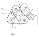
- a special advantage is provided by a tensioning element 10. This serves to adjust the lost arc of the band 4 about the counter-roller 5 so that the band retains a band tensile stress.
- the tensioning element consists essentially of a pressure transducer 21 and a roller 14 which presses against the inner surface of the belt.
- the roller 14 is identical to the guide roller 11.
- FIG. 2 alternatively shows a separate roller 14, over a Pressure transducer 21 and a lever system 22 can be pressed against the belt to build a tensile band tension during or shortly after the separation process.
- the pressure transducer 21 is a hydraulic cylinder in both examples.
- the hydraulic cylinder is controlled position-controlled and / or druckgeregeit.
- a cushioning not shown, is provided.
- spindles are suitable for the tension. Linear drives, pneumatic cylinders, tension over weight load or the like.
- FIG. 3 To further illustrate the invention is in FIG. 3 the calender 1 is shown once with the nip 3 open. Clearly it can be seen that the band 4 no longer touches the counter-roller, but is still stretched by means of the clamping element 10.
- the band 4 is preferably made of plastic, for example PU, PEEK, PFD, Teflon, rubber and mixtures with fibers of glass, aramid or metal fabric.
- the band can also be made of plastic with a thin metal underlayer. Other materials for the band are metal or metal with a plastic underlayer.
- the band is additionally heated.
- the guide rollers can be heated or the belt are heated inductively.
- the tape has a surface roughness of ⁇ 1.0 microns, better less than 0.5 microns.
- the tape has a thickness of 0.5 to 10 mm, preferably 0.8 to 5 mm,
- the band 4 does not have to provide a calendering effect, but can also be used only for effective heating of the web 2 on the heated counter-roller 5 before the web passes the additional nip 19 for elgentliche Glanz- and Glättssteig für für a calender 1
- a calender 1 which has a preheating section for the web 2 under the band 4 or possibly also a Nachfiltier behind the nip with a similar band structure, the band 4 is pressed at a pressure of 0.1 to 1 MPa against the backing roll 5 to the temperature the counter roller 5 to penetrate deep into the paper or the cardboard and so to improve the smoothing result.
- a strip treatment zone is created immediately before or after a supplementary nip 19.
- the advantage of this method of smoothing or of this arrangement lies in the fact that a water- and intestinal-opaque band is used, so that the moisture can not escape from the web 2 in the band treatment zone. The moisture is indeed driven to the cold side of the tape, but remains there stored. Only after the strip treatment zone moisture can escape from the paper web into the environment.
- the illustrated calender 1 can also be combined in a variety of ways with a Mehrwalzenkander or another calender.
Landscapes
- Paper (AREA)
- Treatment Of Fiber Materials (AREA)
- Rolls And Other Rotary Bodies (AREA)
Claims (12)
- Procédé d'ouverture d'un interstice de pressage (3) pour le traitement d'une nappe fibreuse (2), lequel est formé par une bande (4) tournant autour d'au moins deux rouleaux directeurs (11, 12, 13) avec un rouleau conjugué (5), la bande (4) épousant la surface périphérique du rouleau conjugué (5) suivant un angle d'enveloppement supérieur à 5°, la nappe fibreuse (2) étant contrôlée au moyen d'un capteur (6) en vue de déceler des déchirures ou des plis avant l'interstice de pressage et, dans le cas de l'apparition de fissures ou de plis, le capteur (6) envoyant un signal par le biais d'un dispositif de commande (7) à un dispositif de coupe (8), qui en l'espace de 0,9 seconde déplace par moteur au moins un rouleau directeur (11) pendant l'opération de coupe, caractérisé en ce que le dispositif de coupe (8) déplace l'au moins un rouleau directeur (11) en conservant une tension de traction de la bande de telle sorte que la bande (4), après l'opération de coupe, soit espacée du rouleau conjugué (5), la bande (4) étant tendue pendant l'opération de coupe ou immédiatement après celle-ci par le biais d'un élément de tensionnement (10).
- Procédé selon la revendication 1, caractérisé en ce que l'élément de tensionnement (10) maintient au moins approximativement constante la tension de traction de la bande pendant l'opération de coupe.
- Procédé selon la revendication 1 ou 2, caractérisé en ce que le rouleau conjugué (5) est chauffé à une température superficielle supérieure à 130°C.
- Procédé selon l'une quelconque des revendications 1 à 3, caractérisé en ce que le dispositif de coupe (8) déplace un rouleau directeur (11) sur une trajectoire en arc de cercle à l'écart du rouleau conjugué (5).
- Dispositif d'ouverture d'un interstice de pressage (3) servant au traitement d'une nappe fibreuse (2), lequel est formé par une bande (4) tournant autour d'au moins deux rouleaux directeurs (11, 12, 13) avec un rouleau conjugué (5), la bande (4) épousant la surface périphérique du rouleau conjugué (5) suivant un angle d'enveloppement supérieur à 5°, au moins un rouleau directeur (11, 13) étant monté de manière à pouvoir être déplacé au-dessus d'un dispositif de coupe (8), une commande (7) étant prévue, laquelle active le dispositif de coupe (8) sur la base d'une erreur de la nappe fibreuse en mouvement (2) détectée par le biais d'un capteur (6), caractérisé en ce qu'un élément de tensionnement (10) est prévu, lequel peut être sollicité avec une force pour le tensionnement de la bande (4) pendant une opération de coupe.
- Dispositif selon la revendication 5, caractérisé en ce que l'élément de tensionnement (10) comprend un rouleau (14).
- Dispositif selon la revendication 6, caractérisé en ce que le rouleau (14) est l'un des rouleaux directeurs (11).
- Dispositif selon l'une quelconque des revendications 5 à 7, caractérisé en ce que le rouleau conjugué (5) est monté de manière fixe.
- Dispositif selon l'une quelconque des revendications 5 à 8, caractérisé en ce que tous les rouleaux directeurs (11, 12, 13) présentent une distance au rouleau conjugué (5), même dans des conditions de fonctionnement, qui est supérieure à la somme de l'épaisseur de la bande et de la nappe.
- Dispositif selon l'une quelconque des revendications 5 à 9, caractérisé en ce que le dispositif de coupe (8) comprend un moteur de commande (9).
- Dispositif selon l'une quelconque des revendications 5 à 10, caractérisé en ce que l'au moins un rouleau directeur (11), monté dans un levier (15), peut pivoter autour d'un axe de rotation (16).
- Dispositif selon la revendication 11, caractérisé en ce que l'axe de rotation (16) est l'axe d'un deuxième rouleau directeur (12).
Applications Claiming Priority (1)
| Application Number | Priority Date | Filing Date | Title |
|---|---|---|---|
| DE200910046053 DE102009046053A1 (de) | 2009-10-27 | 2009-10-27 | Verfahren und Vorrichtung zum Öffnen eines Nips |
Publications (2)
| Publication Number | Publication Date |
|---|---|
| EP2317008A1 EP2317008A1 (fr) | 2011-05-04 |
| EP2317008B1 true EP2317008B1 (fr) | 2013-09-11 |
Family
ID=42990179
Family Applications (1)
| Application Number | Title | Priority Date | Filing Date |
|---|---|---|---|
| EP20100176729 Not-in-force EP2317008B1 (fr) | 2009-10-27 | 2010-09-15 | Procédé et dispositif d'ouverture d'un interstice de pressage |
Country Status (4)
| Country | Link |
|---|---|
| EP (1) | EP2317008B1 (fr) |
| JP (1) | JP2011094286A (fr) |
| CN (1) | CN102051838A (fr) |
| DE (1) | DE102009046053A1 (fr) |
Families Citing this family (8)
| Publication number | Priority date | Publication date | Assignee | Title |
|---|---|---|---|---|
| DE102010028738A1 (de) | 2010-05-07 | 2011-11-10 | Voith Patent Gmbh | Bahnbehandlungsvorrichtung mit Anlageband |
| DE102011052229A1 (de) * | 2011-07-28 | 2013-01-31 | Andritz Küsters Gmbh | Kalander |
| EP2584093A1 (fr) | 2011-10-20 | 2013-04-24 | Metso Paper Inc. | Système relatif à une chaîne de production d'une bande de fibres |
| DE102011085093A1 (de) | 2011-10-24 | 2013-04-25 | Voith Patent Gmbh | Bahnbehandlungsvorrichtung |
| DE102011085101A1 (de) | 2011-10-24 | 2013-04-25 | Voith Patent Gmbh | Bahnbehandlungsvorrichtung |
| DE202012008035U1 (de) | 2012-08-20 | 2012-09-12 | Voith Patent Gmbh | Vorrichtung zur Behandlung einer Faserstoffbahn |
| DE102015217367B4 (de) | 2015-09-11 | 2017-05-18 | Voith Patent Gmbh | Verfahren zur Behandlung einer Bahn |
| DE102019100884A1 (de) | 2019-01-15 | 2020-07-16 | Voith Patent Gmbh | Vorrichtung und Verfahren zur Behandlung einer Faserstoffbahn |
Family Cites Families (3)
| Publication number | Priority date | Publication date | Assignee | Title |
|---|---|---|---|---|
| DE20012878U1 (de) | 2000-07-26 | 2000-10-05 | Voith Sulzer Papiertechnik Patent GmbH, 89522 Heidenheim | Kalander |
| US6505549B2 (en) | 2000-11-20 | 2003-01-14 | Metso Paper Karlstad Ab | Method of and an apparatus for protecting the jacket upon a web break in a hot shoe press roll nip |
| DE102007045902A1 (de) | 2007-09-26 | 2009-04-09 | Voith Patent Gmbh | Bandkalandervorrichtung und Verfahren zum Betrieb einer Bandkalandervorrichtung |
-
2009
- 2009-10-27 DE DE200910046053 patent/DE102009046053A1/de not_active Withdrawn
-
2010
- 2010-09-15 EP EP20100176729 patent/EP2317008B1/fr not_active Not-in-force
- 2010-10-27 JP JP2010241318A patent/JP2011094286A/ja active Pending
- 2010-10-27 CN CN2010105257057A patent/CN102051838A/zh active Pending
Also Published As
| Publication number | Publication date |
|---|---|
| DE102009046053A1 (de) | 2011-05-05 |
| EP2317008A1 (fr) | 2011-05-04 |
| JP2011094286A (ja) | 2011-05-12 |
| CN102051838A (zh) | 2011-05-11 |
Similar Documents
| Publication | Publication Date | Title |
|---|---|---|
| EP2317008B1 (fr) | Procédé et dispositif d'ouverture d'un interstice de pressage | |
| EP3119583B1 (fr) | Cylindre de pression ou de contact a réglage angulaire | |
| AT3330U1 (de) | Verfahren und vorrichtung zum kalandrieren von papier | |
| CN104690871A (zh) | 新型压延调距装置 | |
| EP1693509B1 (fr) | Surveillance d'un rouleau de presse | |
| EP2586912A1 (fr) | Dispositig de traitement de bande | |
| EP2913435B1 (fr) | Calandre | |
| EP2027333B1 (fr) | Agencement de réglage de bande | |
| EP2753752A1 (fr) | Dispositif de transfert et de stabilisation d'une bande de matière fibreuse | |
| DE202016000260U1 (de) | Pressenvorrichtung | |
| EP1484442B1 (fr) | Procédé de traitement d'une bande, en particulier d'une bande de papier | |
| DE102010061749A1 (de) | Verfahren und Vorrichtung zum Öffnen eines Nips | |
| DE102018127037B4 (de) | Kalander | |
| EP3827123B1 (fr) | Procédé de traitement d'une nappe de tissu et dispositif de traitement d'une nappe de tissu | |
| DE102015217367B4 (de) | Verfahren zur Behandlung einer Bahn | |
| DE202015009116U1 (de) | Unterdrucksteuerung | |
| DE102004017812A1 (de) | Druckhaube | |
| DE10393788T5 (de) | Kartonerzeugnis und Verfahren zum Herstellen desselben | |
| EP1512788B1 (fr) | Machine pour la fabrication ou le traitement d'un matériau en bande | |
| EP4077804B1 (fr) | Dispositif et procédé de transfert d'une nappe de matière fibreuse | |
| DE102007045902A1 (de) | Bandkalandervorrichtung und Verfahren zum Betrieb einer Bandkalandervorrichtung | |
| DE9204175U1 (de) | Bahnabnahme-Vorrichtung | |
| EP2314763B1 (fr) | Dispositif destiné au traitement d'une bande de matière fibreuse | |
| EP2586911A1 (fr) | Dispositif de traitement de bande | |
| DE10393786T5 (de) | LWC-Papier und Verfahren zum Herstellen desselben |
Legal Events
| Date | Code | Title | Description |
|---|---|---|---|
| PUAI | Public reference made under article 153(3) epc to a published international application that has entered the european phase |
Free format text: ORIGINAL CODE: 0009012 |
|
| AK | Designated contracting states |
Kind code of ref document: A1 Designated state(s): AL AT BE BG CH CY CZ DE DK EE ES FI FR GB GR HR HU IE IS IT LI LT LU LV MC MK MT NL NO PL PT RO SE SI SK SM TR |
|
| AX | Request for extension of the european patent |
Extension state: BA ME RS |
|
| 17P | Request for examination filed |
Effective date: 20111104 |
|
| GRAP | Despatch of communication of intention to grant a patent |
Free format text: ORIGINAL CODE: EPIDOSNIGR1 |
|
| INTG | Intention to grant announced |
Effective date: 20130425 |
|
| GRAS | Grant fee paid |
Free format text: ORIGINAL CODE: EPIDOSNIGR3 |
|
| GRAA | (expected) grant |
Free format text: ORIGINAL CODE: 0009210 |
|
| AK | Designated contracting states |
Kind code of ref document: B1 Designated state(s): AL AT BE BG CH CY CZ DE DK EE ES FI FR GB GR HR HU IE IS IT LI LT LU LV MC MK MT NL NO PL PT RO SE SI SK SM TR |
|
| REG | Reference to a national code |
Ref country code: GB Ref legal event code: FG4D Free format text: NOT ENGLISH |
|
| REG | Reference to a national code |
Ref country code: CH Ref legal event code: EP |
|
| REG | Reference to a national code |
Ref country code: AT Ref legal event code: REF Ref document number: 631719 Country of ref document: AT Kind code of ref document: T Effective date: 20130915 |
|
| REG | Reference to a national code |
Ref country code: IE Ref legal event code: FG4D Free format text: LANGUAGE OF EP DOCUMENT: GERMAN |
|
| PGFP | Annual fee paid to national office [announced via postgrant information from national office to epo] |
Ref country code: DE Payment date: 20130927 Year of fee payment: 4 |
|
| REG | Reference to a national code |
Ref country code: DE Ref legal event code: R096 Ref document number: 502010004687 Country of ref document: DE Effective date: 20131107 |
|
| PG25 | Lapsed in a contracting state [announced via postgrant information from national office to epo] |
Ref country code: SE Free format text: LAPSE BECAUSE OF FAILURE TO SUBMIT A TRANSLATION OF THE DESCRIPTION OR TO PAY THE FEE WITHIN THE PRESCRIBED TIME-LIMIT Effective date: 20130911 Ref country code: NO Free format text: LAPSE BECAUSE OF FAILURE TO SUBMIT A TRANSLATION OF THE DESCRIPTION OR TO PAY THE FEE WITHIN THE PRESCRIBED TIME-LIMIT Effective date: 20131211 Ref country code: LT Free format text: LAPSE BECAUSE OF FAILURE TO SUBMIT A TRANSLATION OF THE DESCRIPTION OR TO PAY THE FEE WITHIN THE PRESCRIBED TIME-LIMIT Effective date: 20130911 Ref country code: CY Free format text: LAPSE BECAUSE OF FAILURE TO SUBMIT A TRANSLATION OF THE DESCRIPTION OR TO PAY THE FEE WITHIN THE PRESCRIBED TIME-LIMIT Effective date: 20130717 Ref country code: HR Free format text: LAPSE BECAUSE OF FAILURE TO SUBMIT A TRANSLATION OF THE DESCRIPTION OR TO PAY THE FEE WITHIN THE PRESCRIBED TIME-LIMIT Effective date: 20130911 |
|
| REG | Reference to a national code |
Ref country code: NL Ref legal event code: VDEP Effective date: 20130911 |
|
| REG | Reference to a national code |
Ref country code: LT Ref legal event code: MG4D |
|
| PG25 | Lapsed in a contracting state [announced via postgrant information from national office to epo] |
Ref country code: GR Free format text: LAPSE BECAUSE OF FAILURE TO SUBMIT A TRANSLATION OF THE DESCRIPTION OR TO PAY THE FEE WITHIN THE PRESCRIBED TIME-LIMIT Effective date: 20131212 Ref country code: SI Free format text: LAPSE BECAUSE OF FAILURE TO SUBMIT A TRANSLATION OF THE DESCRIPTION OR TO PAY THE FEE WITHIN THE PRESCRIBED TIME-LIMIT Effective date: 20130911 Ref country code: LV Free format text: LAPSE BECAUSE OF FAILURE TO SUBMIT A TRANSLATION OF THE DESCRIPTION OR TO PAY THE FEE WITHIN THE PRESCRIBED TIME-LIMIT Effective date: 20130911 |
|
| PGFP | Annual fee paid to national office [announced via postgrant information from national office to epo] |
Ref country code: FI Payment date: 20131011 Year of fee payment: 4 |
|
| BERE | Be: lapsed |
Owner name: VOITH PATENT G.M.B.H. Effective date: 20130930 |
|
| PG25 | Lapsed in a contracting state [announced via postgrant information from national office to epo] |
Ref country code: CY Free format text: LAPSE BECAUSE OF FAILURE TO SUBMIT A TRANSLATION OF THE DESCRIPTION OR TO PAY THE FEE WITHIN THE PRESCRIBED TIME-LIMIT Effective date: 20130911 |
|
| PG25 | Lapsed in a contracting state [announced via postgrant information from national office to epo] |
Ref country code: EE Free format text: LAPSE BECAUSE OF FAILURE TO SUBMIT A TRANSLATION OF THE DESCRIPTION OR TO PAY THE FEE WITHIN THE PRESCRIBED TIME-LIMIT Effective date: 20130911 Ref country code: RO Free format text: LAPSE BECAUSE OF FAILURE TO SUBMIT A TRANSLATION OF THE DESCRIPTION OR TO PAY THE FEE WITHIN THE PRESCRIBED TIME-LIMIT Effective date: 20130911 Ref country code: NL Free format text: LAPSE BECAUSE OF FAILURE TO SUBMIT A TRANSLATION OF THE DESCRIPTION OR TO PAY THE FEE WITHIN THE PRESCRIBED TIME-LIMIT Effective date: 20130911 Ref country code: IS Free format text: LAPSE BECAUSE OF FAILURE TO SUBMIT A TRANSLATION OF THE DESCRIPTION OR TO PAY THE FEE WITHIN THE PRESCRIBED TIME-LIMIT Effective date: 20140111 Ref country code: CZ Free format text: LAPSE BECAUSE OF FAILURE TO SUBMIT A TRANSLATION OF THE DESCRIPTION OR TO PAY THE FEE WITHIN THE PRESCRIBED TIME-LIMIT Effective date: 20130911 Ref country code: SK Free format text: LAPSE BECAUSE OF FAILURE TO SUBMIT A TRANSLATION OF THE DESCRIPTION OR TO PAY THE FEE WITHIN THE PRESCRIBED TIME-LIMIT Effective date: 20130911 |
|
| PG25 | Lapsed in a contracting state [announced via postgrant information from national office to epo] |
Ref country code: ES Free format text: LAPSE BECAUSE OF FAILURE TO SUBMIT A TRANSLATION OF THE DESCRIPTION OR TO PAY THE FEE WITHIN THE PRESCRIBED TIME-LIMIT Effective date: 20130911 Ref country code: PL Free format text: LAPSE BECAUSE OF FAILURE TO SUBMIT A TRANSLATION OF THE DESCRIPTION OR TO PAY THE FEE WITHIN THE PRESCRIBED TIME-LIMIT Effective date: 20130911 |
|
| REG | Reference to a national code |
Ref country code: DE Ref legal event code: R097 Ref document number: 502010004687 Country of ref document: DE |
|
| PG25 | Lapsed in a contracting state [announced via postgrant information from national office to epo] |
Ref country code: PT Free format text: LAPSE BECAUSE OF FAILURE TO SUBMIT A TRANSLATION OF THE DESCRIPTION OR TO PAY THE FEE WITHIN THE PRESCRIBED TIME-LIMIT Effective date: 20140113 Ref country code: MC Free format text: LAPSE BECAUSE OF FAILURE TO SUBMIT A TRANSLATION OF THE DESCRIPTION OR TO PAY THE FEE WITHIN THE PRESCRIBED TIME-LIMIT Effective date: 20130911 |
|
| REG | Reference to a national code |
Ref country code: IE Ref legal event code: MM4A |
|
| PLBE | No opposition filed within time limit |
Free format text: ORIGINAL CODE: 0009261 |
|
| STAA | Information on the status of an ep patent application or granted ep patent |
Free format text: STATUS: NO OPPOSITION FILED WITHIN TIME LIMIT |
|
| PG25 | Lapsed in a contracting state [announced via postgrant information from national office to epo] |
Ref country code: BE Free format text: LAPSE BECAUSE OF NON-PAYMENT OF DUE FEES Effective date: 20130930 Ref country code: IE Free format text: LAPSE BECAUSE OF NON-PAYMENT OF DUE FEES Effective date: 20130915 |
|
| REG | Reference to a national code |
Ref country code: FR Ref legal event code: ST Effective date: 20140709 |
|
| 26N | No opposition filed |
Effective date: 20140612 |
|
| PG25 | Lapsed in a contracting state [announced via postgrant information from national office to epo] |
Ref country code: IT Free format text: LAPSE BECAUSE OF FAILURE TO SUBMIT A TRANSLATION OF THE DESCRIPTION OR TO PAY THE FEE WITHIN THE PRESCRIBED TIME-LIMIT Effective date: 20130911 |
|
| REG | Reference to a national code |
Ref country code: DE Ref legal event code: R097 Ref document number: 502010004687 Country of ref document: DE Effective date: 20140612 |
|
| PG25 | Lapsed in a contracting state [announced via postgrant information from national office to epo] |
Ref country code: DK Free format text: LAPSE BECAUSE OF FAILURE TO SUBMIT A TRANSLATION OF THE DESCRIPTION OR TO PAY THE FEE WITHIN THE PRESCRIBED TIME-LIMIT Effective date: 20130911 |
|
| PG25 | Lapsed in a contracting state [announced via postgrant information from national office to epo] |
Ref country code: FR Free format text: LAPSE BECAUSE OF NON-PAYMENT OF DUE FEES Effective date: 20131112 |
|
| REG | Reference to a national code |
Ref country code: DE Ref legal event code: R119 Ref document number: 502010004687 Country of ref document: DE |
|
| PG25 | Lapsed in a contracting state [announced via postgrant information from national office to epo] |
Ref country code: FI Free format text: LAPSE BECAUSE OF NON-PAYMENT OF DUE FEES Effective date: 20140915 |
|
| REG | Reference to a national code |
Ref country code: CH Ref legal event code: PL |
|
| GBPC | Gb: european patent ceased through non-payment of renewal fee |
Effective date: 20140915 |
|
| PG25 | Lapsed in a contracting state [announced via postgrant information from national office to epo] |
Ref country code: SM Free format text: LAPSE BECAUSE OF FAILURE TO SUBMIT A TRANSLATION OF THE DESCRIPTION OR TO PAY THE FEE WITHIN THE PRESCRIBED TIME-LIMIT Effective date: 20130911 |
|
| PG25 | Lapsed in a contracting state [announced via postgrant information from national office to epo] |
Ref country code: MT Free format text: LAPSE BECAUSE OF FAILURE TO SUBMIT A TRANSLATION OF THE DESCRIPTION OR TO PAY THE FEE WITHIN THE PRESCRIBED TIME-LIMIT Effective date: 20130911 Ref country code: TR Free format text: LAPSE BECAUSE OF FAILURE TO SUBMIT A TRANSLATION OF THE DESCRIPTION OR TO PAY THE FEE WITHIN THE PRESCRIBED TIME-LIMIT Effective date: 20130911 |
|
| REG | Reference to a national code |
Ref country code: DE Ref legal event code: R119 Ref document number: 502010004687 Country of ref document: DE Effective date: 20150401 |
|
| PG25 | Lapsed in a contracting state [announced via postgrant information from national office to epo] |
Ref country code: LI Free format text: LAPSE BECAUSE OF NON-PAYMENT OF DUE FEES Effective date: 20140930 Ref country code: HU Free format text: LAPSE BECAUSE OF FAILURE TO SUBMIT A TRANSLATION OF THE DESCRIPTION OR TO PAY THE FEE WITHIN THE PRESCRIBED TIME-LIMIT; INVALID AB INITIO Effective date: 20100915 Ref country code: MK Free format text: LAPSE BECAUSE OF FAILURE TO SUBMIT A TRANSLATION OF THE DESCRIPTION OR TO PAY THE FEE WITHIN THE PRESCRIBED TIME-LIMIT Effective date: 20130911 Ref country code: LU Free format text: LAPSE BECAUSE OF NON-PAYMENT OF DUE FEES Effective date: 20130915 Ref country code: BG Free format text: LAPSE BECAUSE OF FAILURE TO SUBMIT A TRANSLATION OF THE DESCRIPTION OR TO PAY THE FEE WITHIN THE PRESCRIBED TIME-LIMIT Effective date: 20130911 Ref country code: DE Free format text: LAPSE BECAUSE OF NON-PAYMENT OF DUE FEES Effective date: 20150401 Ref country code: CH Free format text: LAPSE BECAUSE OF NON-PAYMENT OF DUE FEES Effective date: 20140930 Ref country code: GB Free format text: LAPSE BECAUSE OF NON-PAYMENT OF DUE FEES Effective date: 20140915 |
|
| REG | Reference to a national code |
Ref country code: AT Ref legal event code: MM01 Ref document number: 631719 Country of ref document: AT Kind code of ref document: T Effective date: 20150915 |
|
| PG25 | Lapsed in a contracting state [announced via postgrant information from national office to epo] |
Ref country code: AT Free format text: LAPSE BECAUSE OF NON-PAYMENT OF DUE FEES Effective date: 20150915 |
|
| PG25 | Lapsed in a contracting state [announced via postgrant information from national office to epo] |
Ref country code: AL Free format text: LAPSE BECAUSE OF FAILURE TO SUBMIT A TRANSLATION OF THE DESCRIPTION OR TO PAY THE FEE WITHIN THE PRESCRIBED TIME-LIMIT Effective date: 20130911 |