EP2317016A2 - Unterwasseraushubgerät - Google Patents
Unterwasseraushubgerät Download PDFInfo
- Publication number
- EP2317016A2 EP2317016A2 EP10251850A EP10251850A EP2317016A2 EP 2317016 A2 EP2317016 A2 EP 2317016A2 EP 10251850 A EP10251850 A EP 10251850A EP 10251850 A EP10251850 A EP 10251850A EP 2317016 A2 EP2317016 A2 EP 2317016A2
- Authority
- EP
- European Patent Office
- Prior art keywords
- excavation
- mass flow
- jet flow
- outlet
- excavation means
- Prior art date
- Legal status (The legal status is an assumption and is not a legal conclusion. Google has not performed a legal analysis and makes no representation as to the accuracy of the status listed.)
- Granted
Links
Images




Classifications
-
- E—FIXED CONSTRUCTIONS
- E02—HYDRAULIC ENGINEERING; FOUNDATIONS; SOIL SHIFTING
- E02F—DREDGING; SOIL-SHIFTING
- E02F3/00—Dredgers; Soil-shifting machines
- E02F3/04—Dredgers; Soil-shifting machines mechanically-driven
- E02F3/88—Dredgers; Soil-shifting machines mechanically-driven with arrangements acting by a sucking or forcing effect, e.g. suction dredgers
- E02F3/90—Component parts, e.g. arrangement or adaptation of pumps
- E02F3/92—Digging elements, e.g. suction heads
- E02F3/9243—Passive suction heads with no mechanical cutting means
- E02F3/925—Passive suction heads with no mechanical cutting means with jets
-
- E—FIXED CONSTRUCTIONS
- E02—HYDRAULIC ENGINEERING; FOUNDATIONS; SOIL SHIFTING
- E02F—DREDGING; SOIL-SHIFTING
- E02F3/00—Dredgers; Soil-shifting machines
- E02F3/04—Dredgers; Soil-shifting machines mechanically-driven
- E02F3/88—Dredgers; Soil-shifting machines mechanically-driven with arrangements acting by a sucking or forcing effect, e.g. suction dredgers
- E02F3/90—Component parts, e.g. arrangement or adaptation of pumps
- E02F3/92—Digging elements, e.g. suction heads
- E02F3/9206—Digging devices using blowing effect only, like jets or propellers
-
- E—FIXED CONSTRUCTIONS
- E02—HYDRAULIC ENGINEERING; FOUNDATIONS; SOIL SHIFTING
- E02F—DREDGING; SOIL-SHIFTING
- E02F5/00—Dredgers or soil-shifting machines for special purposes
- E02F5/28—Dredgers or soil-shifting machines for special purposes for cleaning watercourses or other ways
- E02F5/287—Dredgers or soil-shifting machines for special purposes for cleaning watercourses or other ways with jet nozzles
Definitions
- This invention relates to an improved excavation or mining apparatus, and in particular to an improved underwater excavation apparatus.
- This invention also relates to a method of underwater or sub-sea excavation using such an excavation apparatus.
- Mass flow relates to flow at relatively low pressure and high volume
- jet flow relates to flow at relatively high pressure and low volume
- GB 2 297 777 A (Holandsche Beton Groep NV) discloses an underwater excavation apparatus comprising a hollow body having an inlet and an outlet, at least one pair of impellers coaxially displaced one from the other and rotatably mounted in the hollow body and means for driving the impellers of the/each pair in contrary rotating directions.
- WO 98/027286 A discloses an underwater excavation apparatus comprising a hollow body having at least two inlets and at least one outlet, at least one pair of impellers rotatably mounted in the hollow body, and means for driving the impellers, wherein the at least two inlets are substantially symmetrically disposed around an axis extending from the at least one outlet.
- the driving means cause the impellers to be driven in contra-rotating directions, and one of the impellers is provided within one of the inlets and another of the impellers is provided within another of the inlets.
- GB 2 301 128 B discloses an underwater excavation apparatus comprising an agitator device having mechanical disturbance means and fluid flow disturbance means which comprise a hollow drill bit having at least one hole provided in a side wall thereof, the drill bit providing a plurality of paddles disposed longitudinally and radially extending upon the drill bit and substantially equidistantly spaced one from another.
- WO 2008/065360 A1 discloses an underwater excavation apparatus comprising a hollow body having at least one pair of inlets and at least one outlet, at least one pair of impellers rotatably mounted in the hollow body, means for driving the impellers, and at least one means for moving the underwater excavation apparatus, the at least one moving means being provided on or adjacent to the underwater excavation apparatus.
- an excavation apparatus or mining apparatus particularly an underwater excavation apparatus or mining apparatus, comprising a jet flow means and mass flow means.
- an excavation apparatus particularly an underwater excavation apparatus, comprising at least one mass flow excavation means and at least one jet or jet flow excavation means.
- the excavation apparatus may be adapted for use submerged in a body of fluid/water, e.g. a sea, ocean, estuary, river, lake, loch or the like.
- a body of fluid/water e.g. a sea, ocean, estuary, river, lake, loch or the like.
- the mass flow excavation means is advantageous or beneficial for moving material(s) with relatively low pressure(s) (Kilopascals, KPa), e.g. sand, and/or pre-loosened or disrupted materials.
- the jet flow excavation means is advantageous in cutting through or disrupting material(s), particularly material(s) with relatively high pressure(s) (KPa), e.g. clay.
- the jet flow excavation means may cut through or disrupt material(s) and the mass flow excavation means may move or transport material(s). Therefore, the combination of jet flow excavation means and mass flow excavation means has been found to be beneficial.
- the at least one mass flow excavation means may comprise a housing or hollow tubular member and optionally at least one impeller or rotor provided within the housing or hollow tubular member, which impeller may comprise a plurality of blades.
- the at least one jet flow excavation means may face substantially downwardly, in use, and/or may comprise at least one nozzle or further hollow tubular member.
- the at least one mass flow excavation means may operate at or cause a/the mass flow at a pressure less than a pressure of a jet flow operated at or caused by the at least one respective jet flow excavation means.
- the at least one mass flow excavation means may operate at or cause a/the mass flow at a volume (flow) rate greater than a jet flow volume rate operated at or caused by the at least one respective jet flow excavation means.
- the at least one mass flow excavation means may operate at or cause a/the mass flow at a pressure or around 10 to 50 KPa (KiloPascals).
- the at least one mass flow excavation means may operate at or cause a/the mass flow at a volume rate of around 0.5 to 8.0 m 3 /s, e.g. around 0.5 to 2.5 m 3 /s.
- the at least one jet flow excavation means may operate at or cause a/the jet flow at a pressure of around 100 to 500 KPa (KiloPascals).
- the at least one jet flow excavation means may operate at or cause a/the jet flow at a volume rate of around 0.1 to 0.25 m 3 /s.
- an outlet (e.g. an area of said outlet) of the at least one jet flow excavation means may be provided within an outlet (e.g. an area of said outlet) of the at least one mass flow excavation means.
- a breadth or diameter of the outlet of the at least one jet flow excavation means may typically be around 12 to 15 cm.
- a breadth or diameter of the outlet of the at least one mass flow excavation means may typically be around 75 to 125 cm, e.g. 1m.
- a/the outlet of the at least one jet flow excavation means or nozzle may be substantially longitudinally aligned with or coincident with a/the outlet of the at least one mass flow excavation means.
- At least one mass flow from at least one of the at least one mass flow excavation means may be substantially longitudinally aligned with or substantially parallel to at least one jet flow from at least one of the at least one jet flow excavation means.
- a/the outlet of the at least one mass flow excavation means may comprise a closed shape, e.g. advantageously circular, or alternatively elliptical, oval, oblong square, rectangular or the like.
- a/the outlet of the at least one jet flow excavation means may comprise a closed shape, e.g. advantageously circular, or alternatively, elliptical, oblong, oval, square, rectangular or the like.
- An inlet of the at least one jet flow excavation means may taper or flare outwardly.
- An inlet of the at least one jet flow excavation means may be disposed to face in substantially a same direction as a/the outlet of the mass flow excavation means and/or a/the outlet of the jet flow excavation means.
- A/the outlet of the at least one mass flow excavation means may be disposed so as to face at least partially or preferably substantially downwardly, in use.
- A/the outlet of the at least one jet flow excavation means may be disposed so as to face substantially downwardly, in use.
- A/the inlet of the at least one jet flow excavation means may be disposed in a different direction to a/the respective inlet(s) of the mass flow excavation means.
- A/the inlet of the at least one jet flow excavation means may be disposed so as to face substantially downwardly, in use
- A/the inlet of the at least one jet flow excavation means may be provided with a filter means.
- A/the outlet of the at least one mass flow excavation means may be inverted frusto-conical in shape.
- A/the nozzle of the at least one jet flow excavation means may be substantially cylindrical/elongate in shape.
- An/the outlet of a jet flow means may be surrounded by or provided or contained within a/the outlet of the mass flow means, e.g. in transverse cross-section.
- An/the outlet of the at least one mass flow excavation means may be substantially concentric with or centralised with a/the outlet of or a/the nozzle of the at least one jet flow excavation means.
- An inlet means to the nozzle may be provided between, e.g. longitudinally between, a/the at least one impeller of the mass flow excavation means and an/the outlet of the mass flow excavation means and/or the outlet of the jet flow excavation means.
- Guide vanes may be provided within the housing to guide the mass flow, in use.
- A/the nozzle may be removably connectable to the excavation apparatus. This may allow for replacement of the nozzle, e.g. if damaged, or exchange with another nozzle of different size and/or shape. In this way characteristics, e.g. pressure and/or flow rate, of the jet flow excavation means may be controlled and/or preselected, e.g. dependent upon the material and/or area to be excavated.
- the excavation apparatus may comprise means for tilting or pivoting the at least one mass flow excavation means and/or the at least one jet flow excavation means, preferably together.
- the tilting or pivoting means may allow the at least one mass flow excavation means and/or the at least one jet flow excavation means to tilt or pivot around an axis, e.g. a substantially horizontal axis.
- the excavation apparatus may be tethered to a vessel by a line(s), e.g. tugger lines, e.g. to maintain and/or adjust position of the excavation apparatus.
- a line(s) e.g. tugger lines
- the housing may comprise a hollow body or hollow tubular housing, e.g. having an upper facing inlet and a lower facing outlet.
- At least one pair of impellers coaxially displaced one from the other, and preferably rotatable in contra-rotating directions.
- the impellers(s) may be rotatably mounted in the hollow body.
- the excavation apparatus may comprise first and second excavation units.
- Each unit may comprise a mass flow (excavation) means and a jet flow (excavation) means.
- the units may be transversely disposed or spaced from one another, e.g. upon a frame or structure, e.g. side-by-side.
- the frame or structure may comprise slide means which may act as a means for tilting or pivoting the/each unit, e.g. relative to the frame or structure.
- the first implementation has been found to be particularly advantageous in relatively shallow depths of water, e.g. around 1 to 2 meters.
- the housing may comprise a hollow body having at least two inlets and at least one outlet, at least one pair of impellers rotatably mounted in the hollow body, wherein the at least two inlets are substantially symmetrically disposed around an axis extending from the at least one outlet.
- the housing may be "T” or "Y” - shaped.
- the impellers may be driven in contra-rotating directions.
- One of the impellers may be provided within one of the inlets and another of the impellers may be provided within another of the inlets.
- the mass flow excavation drive means may comprise a hydraulic motor(s), or alternatively an electric motor(s).
- the jet flow excavation drive means may comprise a hydraulic motor(s), or alternatively an electric motor(s).
- the jet flow excavation drive means may comprise a centrifugal pump.
- At least one of the at least one jet flow excavation means may be longitudinally aligned with at least one of the at least one mass flow excavation means.
- an excavation apparatus particularly an underwater excavation apparatus, comprising at least one impeller and at least one jet.
- an outlet of the at least one jet is provided below the at least one impeller.
- a third aspect of the present invention there is provided a combination of a mass flow excavation means and a jet flow excavation means.
- a method of excavating or excavation, particularly underwater excavating or excavation comprising:
- the underwater location or area may comprise or include a seabed, ocean floor, river bed, lake floor, a pipe, pipeline or a trench, or area(s) adjacent thereto or any combination thereof.
- the excavator apparatus may bury or debury object(s) in the underwater location or area.
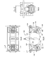
- an excavation apparatus comprising an underwater excavation apparatus, generally designated 2, according to a first embodiment of the present invention.
- the underwater excavation apparatus 2 comprises at least one mass flow excavation means 4 and at least one jet or jet flow excavation means 6.
- the at least one mass flow excavation means 4 comprises a housing 8 and at least one impeller 10 or rotor provided within the housing 8, which impeller 10 comprises a plurality of blades 12.
- the at least one jet flow excavation means 4 comprises at least one nozzle 14.
- the at least one mass flow excavation means 4 typically operates at or causes a mass flow of fluid/water at a pressure of around 10 to 50 KPa (KiloPascals). In use, the at lease one mass flow excavation means 4 operates at or causes the mass flow at a volume rate of around 0.5 to 8.0 m 3 /s, and typically around 0.5 to 2.5 m 3 /s .
- the at least one jet flow excavation means 6 operates at or causes a jet flow of fluid/water at a pressure of around 100 to 500 KPa (KiloPascals). In use, the at least one jet flow excavation means 6 operates at or causes jet flow at a volume rate of around 0.1 to 0.25 m 3 /s.
- An outlet 16 of the at least one jet flow excavation means 6 is provided within an outlet 18 of the at least one mass flow excavation means 4.
- a breadth or diameter of the outlet 16 of the at least one jet flow excavation means 6 is typically around 12 to 15 cm.
- a breadth or diameter of the outlet 18 of the at least one mass flow excavation means 4 is typically around 75 to 125 cm, e.g. 100 cm.
- the outlet 16 of the at least one jet flow excavation means 6 is substantially longitudinally aligned with, or coincident with, the outlet 18 of the at least one mass flow excavation means 4.
- the mass flow is substantially longitudinally aligned with or parallel to the respective jet flow.
- the outlet 18 of the at least one mass flow excavation means 4 comprises a closed shape, and in this embodiment is circular. In alternative embodiments, however, the outlet 18 of the at least one mass flow excavation means 4 can be elliptical, oblong, oval, square, rectangular or the like.
- the outlet 16 of the at least one jet flow excavation means 6 comprises a closed shape, and in this embodiment, is circular. In alternative embodiments, however, the outlet 16 of the at least one jet flow excavation means 6 can be elliptical, oblong, square, oval, rectangular or the like.
- An inlet 20 of the at least one jet flow excavation means 6 tapers or flares outwardly, e.g. in a trumpet-like shape.
- the inlet 20 of the at least one jet flow excavation means 6 is disposed to face in substantially the same direction as the outlet 18 of the mass flow excavation means 4 and/or the outlet 16 of the jet flow excavation means 6.
- the outlet 18 of the at least one mass flow excavation means 4 is disposed so as to face substantially downwardly, in use.
- the outlet 16 of the at least one jet flow excavation means 6 is disposed so as to face substantially downwardly, in use.
- the inlet 20 of the at least one jet flow excavation means 6 is disposed so as to face substantially downwardly, in use. This arrangement has been found to be particularly beneficial.
- the inlet 20 of the at least one jet flow excavation means 6 is provided with a filter means 22.
- the outlet 18 of the at least one mass flow excavation means 4 is inverted frusto-conical in shape.
- the nozzle 14 of the at least one jet flow excavation means 6 is substantially cylindrical and/or elongate in shape.
- the outlet 18 of the at least one mass flow excavation means 6 is substantially concentric with, or centralised with the nozzle 14 of the at least one jet flow excavation means 6.
- the outlet 16 of the at least one jet flow excavation means 6 is therefore contained within an area of the outlet 18 of the at least one mass flow excavation means 4.
- An inlet means 24 to the nozzle 14 is provided between the at least one impeller 10 of the mass flow excavation means 4 and the outlet 18 of the mass flow excavation means 4 and/or the outlet 16 of the jet flow excavation means 6.
- Nozzle 14 is connected to inlet 20 via pipework 21.
- Guide vanes 25 are provided within the housing 8 to guide the mass flow, in use.
- the guide vanes 25 are provided between the impeller 10 and the outlet 18.
- the nozzle 14 is removably connectable to the excavation apparatus 2 at connection means 24. This allows for replacement of the nozzle 14, e.g. if damaged, or exchanged with another nozzle (not shown) of different size and/or shape. In this way characteristics, e.g. pressure and/or flow rate, of the jet flow excavation means 6 can be controlled and/or preselected, e.g. dependent upon the material to be excavated.
- the excavation apparatus 2 comprise means 26 for tilting or pivoting the at least one mass flow excavation means 4 and/or the at least one jet flow excavation means 6.
- the tilting means 26 allows the at least one mass flow excavation means 4 and/or the at least one jet flow excavation means 6 to tilt or pivot an axis Y - Y' around an axis, e.g. a substantially transverse axis X - X'.
- the excavation apparatus 2 can be tethered to a vessel (not shown) by a line(s) (not shown) e.g. tugger lines, e.g. to maintain and/or adjust position of the excavation apparatus 2.
- a line(s) e.g. tugger lines, e.g. to maintain and/or adjust position of the excavation apparatus 2.
- the housing 8 comprises a hollow body or hollow tubular housing, e.g. having an upper facing inlet 26 and lower facing outlet 18.
- a single impeller 10 there is provided within the housing 8 a single impeller 10.
- the impeller(s) 10 is/are rotatably mounted in the housing 8 for rotation around axis Y - Y'.
- the excavation apparatus 2 comprises first and second excavation units 28, 30.
- Each unit 28, 30 comprises a mass flow excavation means 4 and a jet flow excavation means 6.
- the units 28, 30 are transversely disposed or spaced from one another upon a frame or structure 32.
- the frame or structure 32 comprises releasably lockable slide means 34 which with the means for tilting 26 for the/each unit 28, 30, e.g. up to an angle of between 0° and 45° from the vertical, in use.
- the excavation apparatus 2 is typically disposed such that the units 28,30 are located either side of an area, e.g. pipeline, to be excavated.
- the mass flow excavation driving means 36 comprise a hydraulic motor(s) 38. In an alternative implementation an electric motor(s) can be used.
- the jet flow excavation driving means 40 comprises a further hydraulic motor(s) 42.
- an electric motor(s) can be used.
- the outlet 16 of the at least one jet excavation means 6 is provided below the at least one impeller 10.
- the frame 32 provides a plurality of hydraulic feeds 34 - six (6) in this case - two (2) high pressure lines; two (2) low pressure lines; and two (2) case drain lines, one each for each of the hydraulic motor 38 and further hydraulic motor 42.
- the frame 32 also carries first and second ballast 44,45.
- one provides the underwater evacuator 2 and excavates a location or area particularly an underwater location or area, using the underwater excavation 2.
- the underwater area typically comprises a pipe or pipeline or a trench (not shown).
- the excavation can bury or debury object(s) in the location or area.
- FIG. 2(a)to (c) there is illustrated an underwater excavation apparatus, generally designated 102, according to a second embodiment of the present invention.
- Like parts of the apparatus 102 are designated by the same numerals as for the apparatus 2 of the first embodiment, but incremented by "100".
- the units 128, 130 are shown in a tilted disposition. Tiltable longitudinal axes Y - Y' of the units 128, 130 meet (when tilted) at a point below the apparatus 102, which point is typically below a pipeline (not shown), in use.
- FIG. 202 there is illustrated an underwater excavation apparatus, generally designated 202, according to a third embodiment of the present invention.
- Like parts of the apparatus 202 are designated by the same numerals as for the apparatus 2 of the first embodiment, but incremented by "200".
- the housing 208 comprises a hollow body having two outlets 226 and at least one outlet 218, and at least one part of impellers rotatably mounted in the hollow body, wherein the at least two inlets 226 are substantially symmetrically disposed around an axis Y-Y' extending from the at least one outlet 218.
- the impellers are driven in contra-rotating directions.
- One of the impellers is provided within one of the inlets 226 and another of the impellers is provided within another of the inlets 226.
Landscapes
- Engineering & Computer Science (AREA)
- Mechanical Engineering (AREA)
- Mining & Mineral Resources (AREA)
- Civil Engineering (AREA)
- General Engineering & Computer Science (AREA)
- Structural Engineering (AREA)
- Earth Drilling (AREA)
- Jet Pumps And Other Pumps (AREA)
Applications Claiming Priority (1)
| Application Number | Priority Date | Filing Date | Title |
|---|---|---|---|
| GB0919066.1A GB2474891B (en) | 2009-10-30 | 2009-10-30 | Underwater excavation apparatus |
Publications (4)
| Publication Number | Publication Date |
|---|---|
| EP2317016A2 true EP2317016A2 (de) | 2011-05-04 |
| EP2317016A3 EP2317016A3 (de) | 2014-05-14 |
| EP2317016B1 EP2317016B1 (de) | 2017-01-04 |
| EP2317016B2 EP2317016B2 (de) | 2019-12-18 |
Family
ID=41434931
Family Applications (1)
| Application Number | Title | Priority Date | Filing Date |
|---|---|---|---|
| EP10251850.3A Not-in-force EP2317016B2 (de) | 2009-10-30 | 2010-10-26 | Unterwasseraushubgerät |
Country Status (4)
| Country | Link |
|---|---|
| US (1) | US8800176B2 (de) |
| EP (1) | EP2317016B2 (de) |
| DK (1) | DK2317016T4 (de) |
| GB (1) | GB2474891B (de) |
Cited By (4)
| Publication number | Priority date | Publication date | Assignee | Title |
|---|---|---|---|---|
| CN106149784A (zh) * | 2016-08-29 | 2016-11-23 | 温州源杰环保科技有限公司 | 一种河道淤泥清理设备 |
| WO2018037232A3 (en) * | 2016-08-24 | 2018-04-12 | Rotech Group Limited | Improvements in and relating to underwater excavation apparatus |
| WO2019202298A1 (en) * | 2018-04-20 | 2019-10-24 | Rotech Group Limited | Improvements in and relating to underwater excavation apparatus |
| WO2020044021A1 (en) * | 2018-08-29 | 2020-03-05 | Rotech Group Limited | Improved underwater device |
Families Citing this family (4)
| Publication number | Priority date | Publication date | Assignee | Title |
|---|---|---|---|---|
| CN111197328A (zh) * | 2020-03-03 | 2020-05-26 | 无锡东方船研水环境科技有限公司 | 一种带水刀射流式水底污染物清除装置 |
| US11828042B2 (en) * | 2020-05-25 | 2023-11-28 | Wing Marine Llc | Material handling systems and methods |
| WO2024153936A1 (en) * | 2023-01-19 | 2024-07-25 | Sea Jet Systems Limited | Advanced controlled flow excavation system designs |
| CN116378667B (zh) * | 2023-06-02 | 2023-07-28 | 中国科学院地质与地球物理研究所 | 一种矿石采集预处理机构的海底采矿车 |
Citations (4)
| Publication number | Priority date | Publication date | Assignee | Title |
|---|---|---|---|---|
| GB2297777A (en) | 1995-02-07 | 1996-08-14 | Hollandsche Betongroep Nv | Underwater excavation apparatus |
| WO1998027286A1 (en) | 1995-06-21 | 1998-06-25 | Ledingham Chalmers Trustee Company Limited | Improvements in or relating to underwater excavation apparatus |
| GB2301128B (en) | 1995-05-24 | 1999-03-17 | Hector Filippus Alexand Susman | Improvements in or relating to underwater excavation apparatus |
| WO2008065360A1 (en) | 2006-11-29 | 2008-06-05 | Rotech Holdings Limited | Underwater excavation apparatus |
Family Cites Families (15)
| Publication number | Priority date | Publication date | Assignee | Title |
|---|---|---|---|---|
| US2711598A (en) * | 1951-07-31 | 1955-06-28 | Jr James H Craggs | Hydraulic excavator |
| US2956354A (en) * | 1956-06-14 | 1960-10-18 | Charles W Varner | Dredging apparatus |
| US3412862A (en) * | 1967-09-07 | 1968-11-26 | Merle P. Chaplin | Method and apparatus for cleaning areas overlain by a water body |
| US4112695A (en) * | 1977-02-28 | 1978-09-12 | Santa Fe International Corp. | Sea sled for entrenching pipe |
| US4389139A (en) * | 1980-09-19 | 1983-06-21 | Norman Robert M | Oscillating jet head underwater trenching apparatus |
| DE3833831A1 (de) * | 1988-10-05 | 1990-04-12 | Stefan Schoell | Absaugvorrichtung fuer gewaesserablagerungen |
| GB2315787B (en) * | 1996-03-01 | 1999-07-21 | Seabed Impeller Levelling And | Dredging apparatus |
| GB9807070D0 (en) * | 1998-04-01 | 1998-06-03 | Seabed Impeller Levelling And | Dredging apparatus |
| JP3992854B2 (ja) * | 1998-09-14 | 2007-10-17 | 株式会社東洋電機工業所 | ジェット水を噴出可能な水中掘削装置及びジェットエアを噴出可能な水中掘削装置 |
| DE19960361A1 (de) * | 1999-12-14 | 2001-06-21 | Krupp Foerdertechnik Gmbh | Schleppkopf für Saugbagger |
| GB0111411D0 (en) * | 2001-05-09 | 2001-07-04 | Psl Technology Ltd | Apparatus and method |
| JP3755587B2 (ja) * | 2001-06-29 | 2006-03-15 | 株式会社東洋電機工業所 | 土砂等除去装置 |
| NL1020754C2 (nl) † | 2002-06-04 | 2003-12-08 | Seatools B V | Inrichting voor het verwijderen van sediment en functie-eenheid voor toepassing daarin. |
| GB0227016D0 (en) * | 2002-11-19 | 2002-12-24 | Redding John | Dredging,scouring & excavation |
| GB2459700B (en) * | 2008-05-01 | 2012-11-14 | Rotech Holdings Ltd | Improvements in and relating to underwater excavation apparatus |
-
2009
- 2009-10-30 GB GB0919066.1A patent/GB2474891B/en active Active
-
2010
- 2010-10-26 EP EP10251850.3A patent/EP2317016B2/de not_active Not-in-force
- 2010-10-26 DK DK10251850.3T patent/DK2317016T4/da active
- 2010-10-29 US US12/915,329 patent/US8800176B2/en not_active Expired - Fee Related
Patent Citations (4)
| Publication number | Priority date | Publication date | Assignee | Title |
|---|---|---|---|---|
| GB2297777A (en) | 1995-02-07 | 1996-08-14 | Hollandsche Betongroep Nv | Underwater excavation apparatus |
| GB2301128B (en) | 1995-05-24 | 1999-03-17 | Hector Filippus Alexand Susman | Improvements in or relating to underwater excavation apparatus |
| WO1998027286A1 (en) | 1995-06-21 | 1998-06-25 | Ledingham Chalmers Trustee Company Limited | Improvements in or relating to underwater excavation apparatus |
| WO2008065360A1 (en) | 2006-11-29 | 2008-06-05 | Rotech Holdings Limited | Underwater excavation apparatus |
Cited By (9)
| Publication number | Priority date | Publication date | Assignee | Title |
|---|---|---|---|---|
| WO2018037232A3 (en) * | 2016-08-24 | 2018-04-12 | Rotech Group Limited | Improvements in and relating to underwater excavation apparatus |
| EP4036321A1 (de) * | 2016-08-24 | 2022-08-03 | Rotech Group Limited | Verbesserungen an oder im zusammenhang mit einer unterwasseraushubvorrichtung |
| EP4036322A1 (de) * | 2016-08-24 | 2022-08-03 | Rotech Group Limited | Verbesserungen an oder im zusammenhang mit einer unterwasseraushubvorrichtung |
| US12110653B2 (en) | 2016-08-24 | 2024-10-08 | Rotech Group Limited | Underwater excavation apparatus |
| CN106149784A (zh) * | 2016-08-29 | 2016-11-23 | 温州源杰环保科技有限公司 | 一种河道淤泥清理设备 |
| WO2019202298A1 (en) * | 2018-04-20 | 2019-10-24 | Rotech Group Limited | Improvements in and relating to underwater excavation apparatus |
| WO2020044021A1 (en) * | 2018-08-29 | 2020-03-05 | Rotech Group Limited | Improved underwater device |
| GB2576978A (en) * | 2018-08-29 | 2020-03-11 | Rotech Group Ltd | Improved underwater device |
| GB2576978B (en) * | 2018-08-29 | 2021-06-23 | Rotech Group Ltd | Improved underwater device |
Also Published As
| Publication number | Publication date |
|---|---|
| EP2317016A3 (de) | 2014-05-14 |
| US8800176B2 (en) | 2014-08-12 |
| GB2474891A (en) | 2011-05-04 |
| GB2474891B (en) | 2015-02-18 |
| EP2317016B2 (de) | 2019-12-18 |
| EP2317016B1 (de) | 2017-01-04 |
| DK2317016T4 (da) | 2020-03-23 |
| US20110099859A1 (en) | 2011-05-05 |
| DK2317016T3 (en) | 2017-04-10 |
| GB0919066D0 (en) | 2009-12-16 |
Similar Documents
| Publication | Publication Date | Title |
|---|---|---|
| US8800176B2 (en) | Underwater excavation apparatus | |
| DK2281091T3 (en) | IMPROVEMENTS IN AND IN CONNECTION WITH UNDERGRADING EXCAVATOR | |
| KR102068673B1 (ko) | 준설용 컷터 | |
| CN112055770B (zh) | 水下挖掘设备的改进及相关 | |
| EP2586962B1 (de) | Schlammaushub-Abführsystem für eine Maschine zur Herstellung von Schlitzwänden. | |
| JP7319946B2 (ja) | 浚渫装置と浚渫システム、及び浚渫方法 | |
| EA008036B1 (ru) | Устройство для подводной выемки и всасывания грунта | |
| AU2006217931B2 (en) | Cutter head for dredging soil and method for dredging by means of this cutter head | |
| EP4466410B1 (de) | Verbesserungen an und im zusammenhang mit einer unterwasseraushubvorrichtung | |
| CN101148894A (zh) | 船载冲搅一体式泥塘河道清淤装置 | |
| EP3259410B1 (de) | Tauchfähiges fahrzeug zur erschaffung eines grabens in einem unterseeboden | |
| GB2538974A (en) | Underwater excavation apparatus | |
| EP3329056B1 (de) | Separatorvorrichtung | |
| JP7252099B2 (ja) | 浚渫用アタッチメント及び浚渫システム | |
| US20240401305A1 (en) | Subsea Blower Device | |
| US20150007463A1 (en) | Method and apparatus for underwater pile excavating | |
| JP7224933B2 (ja) | 浚渫装置および浚渫方法 | |
| EP0521032B1 (de) | Verbesserungen an meeresbergbautechnik | |
| WO1988003197A1 (en) | Cutting device |
Legal Events
| Date | Code | Title | Description |
|---|---|---|---|
| PUAI | Public reference made under article 153(3) epc to a published international application that has entered the european phase |
Free format text: ORIGINAL CODE: 0009012 |
|
| 17P | Request for examination filed |
Effective date: 20101102 |
|
| AK | Designated contracting states |
Kind code of ref document: A2 Designated state(s): AL AT BE BG CH CY CZ DE DK EE ES FI FR GB GR HR HU IE IS IT LI LT LU LV MC MK MT NL NO PL PT RO RS SE SI SK SM TR |
|
| AX | Request for extension of the european patent |
Extension state: BA ME |
|
| RAP1 | Party data changed (applicant data changed or rights of an application transferred) |
Owner name: ROTECH LIMITED |
|
| 111L | Licence recorded |
Designated state(s): AL AT BE BG CH CY CZ DE DK EE ES FI FR GB GR HR HU IE IS IT LT LU LV MC MK MT NL NO PL PT RO RS SE SI SK SM TR Free format text: EXCLUSIVE LICENSE Name of requester: REEF SUBSEA UK LIMITED, GB Effective date: 20120308 |
|
| R11L | Licence recorded (corrected) |
Designated state(s): AL AT BE BG CH CY CZ DE DK EE ES FI FR GB GR HR HU IE IS IT LT LU LV MC MK MT NL NO PL PT RO RS SE SI SK SM TR Free format text: EXCLUSIVE LICENSE Name of requester: REEF SUBSEA UK LIMITED, GB Effective date: 20120308 |
|
| RIC1 | Information provided on ipc code assigned before grant |
Ipc: E02F 5/28 20060101AFI20131217BHEP Ipc: E02F 3/92 20060101ALI20131217BHEP |
|
| PUAL | Search report despatched |
Free format text: ORIGINAL CODE: 0009013 |
|
| AK | Designated contracting states |
Kind code of ref document: A3 Designated state(s): AL AT BE BG CH CY CZ DE DK EE ES FI FR GB GR HR HU IE IS IT LI LT LU LV MC MK MT NL NO PL PT RO RS SE SI SK SM TR |
|
| AX | Request for extension of the european patent |
Extension state: BA ME |
|
| RIC1 | Information provided on ipc code assigned before grant |
Ipc: E02F 5/28 20060101AFI20140409BHEP Ipc: E02F 3/92 20060101ALI20140409BHEP |
|
| GRAP | Despatch of communication of intention to grant a patent |
Free format text: ORIGINAL CODE: EPIDOSNIGR1 |
|
| INTG | Intention to grant announced |
Effective date: 20160617 |
|
| GRAS | Grant fee paid |
Free format text: ORIGINAL CODE: EPIDOSNIGR3 |
|
| GRAA | (expected) grant |
Free format text: ORIGINAL CODE: 0009210 |
|
| STAA | Information on the status of an ep patent application or granted ep patent |
Free format text: STATUS: THE PATENT HAS BEEN GRANTED |
|
| 111L | Licence recorded |
Designated state(s): AL AT BE BG CH CY CZ DE DK EE ES FI FR GB GR HR HU IE IS IT LT LU LV MC MK MT NL NO PL PT RO RS SE SI SK SM TR Free format text: EXCLUSIVE LICENSE Name of requester: REEF SUBSEA UK LIMITED, GB Effective date: 20120308 |
|
| AK | Designated contracting states |
Kind code of ref document: B1 Designated state(s): AL AT BE BG CH CY CZ DE DK EE ES FI FR GB GR HR HU IE IS IT LI LT LU LV MC MK MT NL NO PL PT RO RS SE SI SK SM TR |
|
| REG | Reference to a national code |
Ref country code: GB Ref legal event code: FG4D |
|
| REG | Reference to a national code |
Ref country code: CH Ref legal event code: EP Ref country code: CH Ref legal event code: PK Free format text: ERGAENZUNG LIZENZEINTRAG: AUSSCHLIESSLICHE LIZENZ |
|
| REG | Reference to a national code |
Ref country code: AT Ref legal event code: REF Ref document number: 859377 Country of ref document: AT Kind code of ref document: T Effective date: 20170115 |
|
| REG | Reference to a national code |
Ref country code: IE Ref legal event code: FG4D |
|
| RAP2 | Party data changed (patent owner data changed or rights of a patent transferred) |
Owner name: JAMES FISHER MFE LIMITED |
|
| REG | Reference to a national code |
Ref country code: DE Ref legal event code: R096 Ref document number: 602010039294 Country of ref document: DE |
|
| REG | Reference to a national code |
Ref country code: DE Ref legal event code: R081 Ref document number: 602010039294 Country of ref document: DE Owner name: JAMES FISHER OFFSHORE LIMITED, OLDMELDRUM, GB Free format text: FORMER OWNER: ROTECH LTD., ABERDEEN, GB Ref country code: DE Ref legal event code: R081 Ref document number: 602010039294 Country of ref document: DE Owner name: JAMES FISHER MFE LIMITED, BARROW IN FURNESS, GB Free format text: FORMER OWNER: ROTECH LTD., ABERDEEN, GB |
|
| REG | Reference to a national code |
Ref country code: DK Ref legal event code: T3 Effective date: 20170405 |
|
| REG | Reference to a national code |
Ref country code: NL Ref legal event code: FP |
|
| REG | Reference to a national code |
Ref country code: LT Ref legal event code: MG4D |
|
| REG | Reference to a national code |
Ref country code: NO Ref legal event code: T2 Effective date: 20170104 |
|
| REG | Reference to a national code |
Ref country code: AT Ref legal event code: MK05 Ref document number: 859377 Country of ref document: AT Kind code of ref document: T Effective date: 20170104 |
|
| PG25 | Lapsed in a contracting state [announced via postgrant information from national office to epo] |
Ref country code: LT Free format text: LAPSE BECAUSE OF FAILURE TO SUBMIT A TRANSLATION OF THE DESCRIPTION OR TO PAY THE FEE WITHIN THE PRESCRIBED TIME-LIMIT Effective date: 20170104 Ref country code: HR Free format text: LAPSE BECAUSE OF FAILURE TO SUBMIT A TRANSLATION OF THE DESCRIPTION OR TO PAY THE FEE WITHIN THE PRESCRIBED TIME-LIMIT Effective date: 20170104 Ref country code: FI Free format text: LAPSE BECAUSE OF FAILURE TO SUBMIT A TRANSLATION OF THE DESCRIPTION OR TO PAY THE FEE WITHIN THE PRESCRIBED TIME-LIMIT Effective date: 20170104 Ref country code: IS Free format text: LAPSE BECAUSE OF FAILURE TO SUBMIT A TRANSLATION OF THE DESCRIPTION OR TO PAY THE FEE WITHIN THE PRESCRIBED TIME-LIMIT Effective date: 20170504 Ref country code: GR Free format text: LAPSE BECAUSE OF FAILURE TO SUBMIT A TRANSLATION OF THE DESCRIPTION OR TO PAY THE FEE WITHIN THE PRESCRIBED TIME-LIMIT Effective date: 20170405 |
|
| PG25 | Lapsed in a contracting state [announced via postgrant information from national office to epo] |
Ref country code: AT Free format text: LAPSE BECAUSE OF FAILURE TO SUBMIT A TRANSLATION OF THE DESCRIPTION OR TO PAY THE FEE WITHIN THE PRESCRIBED TIME-LIMIT Effective date: 20170104 Ref country code: SE Free format text: LAPSE BECAUSE OF FAILURE TO SUBMIT A TRANSLATION OF THE DESCRIPTION OR TO PAY THE FEE WITHIN THE PRESCRIBED TIME-LIMIT Effective date: 20170104 Ref country code: RS Free format text: LAPSE BECAUSE OF FAILURE TO SUBMIT A TRANSLATION OF THE DESCRIPTION OR TO PAY THE FEE WITHIN THE PRESCRIBED TIME-LIMIT Effective date: 20170104 Ref country code: PT Free format text: LAPSE BECAUSE OF FAILURE TO SUBMIT A TRANSLATION OF THE DESCRIPTION OR TO PAY THE FEE WITHIN THE PRESCRIBED TIME-LIMIT Effective date: 20170504 Ref country code: ES Free format text: LAPSE BECAUSE OF FAILURE TO SUBMIT A TRANSLATION OF THE DESCRIPTION OR TO PAY THE FEE WITHIN THE PRESCRIBED TIME-LIMIT Effective date: 20170104 Ref country code: LV Free format text: LAPSE BECAUSE OF FAILURE TO SUBMIT A TRANSLATION OF THE DESCRIPTION OR TO PAY THE FEE WITHIN THE PRESCRIBED TIME-LIMIT Effective date: 20170104 Ref country code: BG Free format text: LAPSE BECAUSE OF FAILURE TO SUBMIT A TRANSLATION OF THE DESCRIPTION OR TO PAY THE FEE WITHIN THE PRESCRIBED TIME-LIMIT Effective date: 20170404 Ref country code: PL Free format text: LAPSE BECAUSE OF FAILURE TO SUBMIT A TRANSLATION OF THE DESCRIPTION OR TO PAY THE FEE WITHIN THE PRESCRIBED TIME-LIMIT Effective date: 20170104 |
|
| REG | Reference to a national code |
Ref country code: FR Ref legal event code: PLFP Year of fee payment: 8 |
|
| REG | Reference to a national code |
Ref country code: DE Ref legal event code: R026 Ref document number: 602010039294 Country of ref document: DE |
|
| PLBI | Opposition filed |
Free format text: ORIGINAL CODE: 0009260 |
|
| PG25 | Lapsed in a contracting state [announced via postgrant information from national office to epo] |
Ref country code: RO Free format text: LAPSE BECAUSE OF FAILURE TO SUBMIT A TRANSLATION OF THE DESCRIPTION OR TO PAY THE FEE WITHIN THE PRESCRIBED TIME-LIMIT Effective date: 20170104 Ref country code: IT Free format text: LAPSE BECAUSE OF FAILURE TO SUBMIT A TRANSLATION OF THE DESCRIPTION OR TO PAY THE FEE WITHIN THE PRESCRIBED TIME-LIMIT Effective date: 20170104 Ref country code: CZ Free format text: LAPSE BECAUSE OF FAILURE TO SUBMIT A TRANSLATION OF THE DESCRIPTION OR TO PAY THE FEE WITHIN THE PRESCRIBED TIME-LIMIT Effective date: 20170104 Ref country code: EE Free format text: LAPSE BECAUSE OF FAILURE TO SUBMIT A TRANSLATION OF THE DESCRIPTION OR TO PAY THE FEE WITHIN THE PRESCRIBED TIME-LIMIT Effective date: 20170104 Ref country code: SK Free format text: LAPSE BECAUSE OF FAILURE TO SUBMIT A TRANSLATION OF THE DESCRIPTION OR TO PAY THE FEE WITHIN THE PRESCRIBED TIME-LIMIT Effective date: 20170104 |
|
| PLAX | Notice of opposition and request to file observation + time limit sent |
Free format text: ORIGINAL CODE: EPIDOSNOBS2 |
|
| 26 | Opposition filed |
Opponent name: SEATOOLS B.V. Effective date: 20171004 |
|
| PG25 | Lapsed in a contracting state [announced via postgrant information from national office to epo] |
Ref country code: SM Free format text: LAPSE BECAUSE OF FAILURE TO SUBMIT A TRANSLATION OF THE DESCRIPTION OR TO PAY THE FEE WITHIN THE PRESCRIBED TIME-LIMIT Effective date: 20170104 |
|
| PG25 | Lapsed in a contracting state [announced via postgrant information from national office to epo] |
Ref country code: SI Free format text: LAPSE BECAUSE OF FAILURE TO SUBMIT A TRANSLATION OF THE DESCRIPTION OR TO PAY THE FEE WITHIN THE PRESCRIBED TIME-LIMIT Effective date: 20170104 |
|
| PLBB | Reply of patent proprietor to notice(s) of opposition received |
Free format text: ORIGINAL CODE: EPIDOSNOBS3 |
|
| PG25 | Lapsed in a contracting state [announced via postgrant information from national office to epo] |
Ref country code: MC Free format text: LAPSE BECAUSE OF FAILURE TO SUBMIT A TRANSLATION OF THE DESCRIPTION OR TO PAY THE FEE WITHIN THE PRESCRIBED TIME-LIMIT Effective date: 20170104 |
|
| REG | Reference to a national code |
Ref country code: CH Ref legal event code: PL |
|
| REG | Reference to a national code |
Ref country code: IE Ref legal event code: MM4A |
|
| PG25 | Lapsed in a contracting state [announced via postgrant information from national office to epo] |
Ref country code: LU Free format text: LAPSE BECAUSE OF NON-PAYMENT OF DUE FEES Effective date: 20171026 Ref country code: LI Free format text: LAPSE BECAUSE OF NON-PAYMENT OF DUE FEES Effective date: 20171031 Ref country code: CH Free format text: LAPSE BECAUSE OF NON-PAYMENT OF DUE FEES Effective date: 20171031 |
|
| REG | Reference to a national code |
Ref country code: BE Ref legal event code: MM Effective date: 20171031 |
|
| PG25 | Lapsed in a contracting state [announced via postgrant information from national office to epo] |
Ref country code: BE Free format text: LAPSE BECAUSE OF NON-PAYMENT OF DUE FEES Effective date: 20171031 |
|
| REG | Reference to a national code |
Ref country code: FR Ref legal event code: PLFP Year of fee payment: 9 |
|
| PG25 | Lapsed in a contracting state [announced via postgrant information from national office to epo] |
Ref country code: MT Free format text: LAPSE BECAUSE OF NON-PAYMENT OF DUE FEES Effective date: 20171026 |
|
| PG25 | Lapsed in a contracting state [announced via postgrant information from national office to epo] |
Ref country code: IE Free format text: LAPSE BECAUSE OF NON-PAYMENT OF DUE FEES Effective date: 20171026 |
|
| PG25 | Lapsed in a contracting state [announced via postgrant information from national office to epo] |
Ref country code: HU Free format text: LAPSE BECAUSE OF FAILURE TO SUBMIT A TRANSLATION OF THE DESCRIPTION OR TO PAY THE FEE WITHIN THE PRESCRIBED TIME-LIMIT; INVALID AB INITIO Effective date: 20101026 |
|
| APAH | Appeal reference modified |
Free format text: ORIGINAL CODE: EPIDOSCREFNO |
|
| APBM | Appeal reference recorded |
Free format text: ORIGINAL CODE: EPIDOSNREFNO |
|
| APBP | Date of receipt of notice of appeal recorded |
Free format text: ORIGINAL CODE: EPIDOSNNOA2O |
|
| APBU | Appeal procedure closed |
Free format text: ORIGINAL CODE: EPIDOSNNOA9O |
|
| PG25 | Lapsed in a contracting state [announced via postgrant information from national office to epo] |
Ref country code: CY Free format text: LAPSE BECAUSE OF NON-PAYMENT OF DUE FEES Effective date: 20170104 |
|
| PUAH | Patent maintained in amended form |
Free format text: ORIGINAL CODE: 0009272 |
|
| STAA | Information on the status of an ep patent application or granted ep patent |
Free format text: STATUS: PATENT MAINTAINED AS AMENDED |
|
| PG25 | Lapsed in a contracting state [announced via postgrant information from national office to epo] |
Ref country code: MK Free format text: LAPSE BECAUSE OF FAILURE TO SUBMIT A TRANSLATION OF THE DESCRIPTION OR TO PAY THE FEE WITHIN THE PRESCRIBED TIME-LIMIT Effective date: 20170104 |
|
| 27A | Patent maintained in amended form |
Effective date: 20191218 |
|
| AK | Designated contracting states |
Kind code of ref document: B2 Designated state(s): AL AT BE BG CH CY CZ DE DK EE ES FI FR GB GR HR HU IE IS IT LI LT LU LV MC MK MT NL NO PL PT RO RS SE SI SK SM TR |
|
| REG | Reference to a national code |
Ref country code: DE Ref legal event code: R102 Ref document number: 602010039294 Country of ref document: DE |
|
| REG | Reference to a national code |
Ref country code: DK Ref legal event code: T4 Effective date: 20200316 |
|
| PG25 | Lapsed in a contracting state [announced via postgrant information from national office to epo] |
Ref country code: TR Free format text: LAPSE BECAUSE OF FAILURE TO SUBMIT A TRANSLATION OF THE DESCRIPTION OR TO PAY THE FEE WITHIN THE PRESCRIBED TIME-LIMIT Effective date: 20170104 |
|
| REG | Reference to a national code |
Ref country code: NL Ref legal event code: FP |
|
| REG | Reference to a national code |
Ref country code: NO Ref legal event code: TB2 |
|
| PG25 | Lapsed in a contracting state [announced via postgrant information from national office to epo] |
Ref country code: AL Free format text: LAPSE BECAUSE OF FAILURE TO SUBMIT A TRANSLATION OF THE DESCRIPTION OR TO PAY THE FEE WITHIN THE PRESCRIBED TIME-LIMIT Effective date: 20170104 |
|
| REG | Reference to a national code |
Ref country code: DE Ref legal event code: R082 Ref document number: 602010039294 Country of ref document: DE Representative=s name: MARKS & CLERK (LUXEMBOURG) LLP, LU Ref country code: DE Ref legal event code: R081 Ref document number: 602010039294 Country of ref document: DE Owner name: JAMES FISHER OFFSHORE LIMITED, OLDMELDRUM, GB Free format text: FORMER OWNER: JAMES FISHER MFE LIMITED, BARROW IN FURNESS, CUMBRIA, GB |
|
| REG | Reference to a national code |
Ref country code: GB Ref legal event code: 732E Free format text: REGISTERED BETWEEN 20210708 AND 20210714 |
|
| REG | Reference to a national code |
Ref country code: NO Ref legal event code: CHAD Owner name: JAMES FISHER OFFSHORE LIMITED, GB |
|
| REG | Reference to a national code |
Ref country code: NL Ref legal event code: PD Owner name: JAMES FISHER OFFSHORE LIMITED; GB Free format text: DETAILS ASSIGNMENT: CHANGE OF OWNER(S), ASSIGNMENT; FORMER OWNER NAME: JAMES FISHER MFE LIMITED Effective date: 20211206 |
|
| PGFP | Annual fee paid to national office [announced via postgrant information from national office to epo] |
Ref country code: NL Payment date: 20230915 Year of fee payment: 14 Ref country code: GB Payment date: 20230907 Year of fee payment: 14 |
|
| PGFP | Annual fee paid to national office [announced via postgrant information from national office to epo] |
Ref country code: FR Payment date: 20230911 Year of fee payment: 14 |
|
| PGFP | Annual fee paid to national office [announced via postgrant information from national office to epo] |
Ref country code: NO Payment date: 20231010 Year of fee payment: 14 Ref country code: DK Payment date: 20231016 Year of fee payment: 14 Ref country code: DE Payment date: 20230830 Year of fee payment: 14 |
|
| REG | Reference to a national code |
Ref country code: DE Ref legal event code: R119 Ref document number: 602010039294 Country of ref document: DE |
|
| REG | Reference to a national code |
Ref country code: DK Ref legal event code: EBP Effective date: 20241031 |
|
| REG | Reference to a national code |
Ref country code: NL Ref legal event code: MM Effective date: 20241101 |
|
| GBPC | Gb: european patent ceased through non-payment of renewal fee |
Effective date: 20241026 |
|
| PG25 | Lapsed in a contracting state [announced via postgrant information from national office to epo] |
Ref country code: DE Free format text: LAPSE BECAUSE OF NON-PAYMENT OF DUE FEES Effective date: 20250501 |
|
| PG25 | Lapsed in a contracting state [announced via postgrant information from national office to epo] |
Ref country code: GB Free format text: LAPSE BECAUSE OF NON-PAYMENT OF DUE FEES Effective date: 20241026 |
|
| PG25 | Lapsed in a contracting state [announced via postgrant information from national office to epo] |
Ref country code: NO Free format text: LAPSE BECAUSE OF NON-PAYMENT OF DUE FEES Effective date: 20241031 |
|
| PG25 | Lapsed in a contracting state [announced via postgrant information from national office to epo] |
Ref country code: NL Free format text: LAPSE BECAUSE OF NON-PAYMENT OF DUE FEES Effective date: 20241101 |
|
| PG25 | Lapsed in a contracting state [announced via postgrant information from national office to epo] |
Ref country code: FR Free format text: LAPSE BECAUSE OF NON-PAYMENT OF DUE FEES Effective date: 20241031 |
|
| PG25 | Lapsed in a contracting state [announced via postgrant information from national office to epo] |
Ref country code: DK Free format text: LAPSE BECAUSE OF NON-PAYMENT OF DUE FEES Effective date: 20241031 |