EP2317059A1 - Profil composite pour éléments de fenêtres, de porte ou de façades doté de propriétés ignifuges prédéfinies et connecteur et élément de raccordement correspondants - Google Patents
Profil composite pour éléments de fenêtres, de porte ou de façades doté de propriétés ignifuges prédéfinies et connecteur et élément de raccordement correspondants Download PDFInfo
- Publication number
- EP2317059A1 EP2317059A1 EP09013581A EP09013581A EP2317059A1 EP 2317059 A1 EP2317059 A1 EP 2317059A1 EP 09013581 A EP09013581 A EP 09013581A EP 09013581 A EP09013581 A EP 09013581A EP 2317059 A1 EP2317059 A1 EP 2317059A1
- Authority
- EP
- European Patent Office
- Prior art keywords
- outer profile
- profile part
- connection element
- insulating
- connecting element
- Prior art date
- Legal status (The legal status is an assumption and is not a legal conclusion. Google has not performed a legal analysis and makes no representation as to the accuracy of the status listed.)
- Granted
Links
Images


Classifications
-
- E—FIXED CONSTRUCTIONS
- E06—DOORS, WINDOWS, SHUTTERS, OR ROLLER BLINDS IN GENERAL; LADDERS
- E06B—FIXED OR MOVABLE CLOSURES FOR OPENINGS IN BUILDINGS, VEHICLES, FENCES OR LIKE ENCLOSURES IN GENERAL, e.g. DOORS, WINDOWS, BLINDS, GATES
- E06B3/00—Window sashes, door leaves, or like elements for closing wall or like openings; Layout of fixed or moving closures, e.g. windows in wall or like openings; Features of rigidly-mounted outer frames relating to the mounting of wing frames
- E06B3/04—Wing frames not characterised by the manner of movement
- E06B3/263—Frames with special provision for insulation
- E06B3/26301—Frames with special provision for insulation with prefabricated insulating strips between two metal section members
- E06B3/26303—Frames with special provision for insulation with prefabricated insulating strips between two metal section members with thin strips, e.g. defining a hollow space between the metal section members
-
- E—FIXED CONSTRUCTIONS
- E06—DOORS, WINDOWS, SHUTTERS, OR ROLLER BLINDS IN GENERAL; LADDERS
- E06B—FIXED OR MOVABLE CLOSURES FOR OPENINGS IN BUILDINGS, VEHICLES, FENCES OR LIKE ENCLOSURES IN GENERAL, e.g. DOORS, WINDOWS, BLINDS, GATES
- E06B5/00—Doors, windows, or like closures for special purposes; Border constructions therefor
- E06B5/10—Doors, windows, or like closures for special purposes; Border constructions therefor for protection against air-raid or other war-like action; for other protective purposes
- E06B5/16—Fireproof doors or similar closures; Adaptations of fixed constructions therefor
-
- E—FIXED CONSTRUCTIONS
- E06—DOORS, WINDOWS, SHUTTERS, OR ROLLER BLINDS IN GENERAL; LADDERS
- E06B—FIXED OR MOVABLE CLOSURES FOR OPENINGS IN BUILDINGS, VEHICLES, FENCES OR LIKE ENCLOSURES IN GENERAL, e.g. DOORS, WINDOWS, BLINDS, GATES
- E06B3/00—Window sashes, door leaves, or like elements for closing wall or like openings; Layout of fixed or moving closures, e.g. windows in wall or like openings; Features of rigidly-mounted outer frames relating to the mounting of wing frames
- E06B3/04—Wing frames not characterised by the manner of movement
- E06B3/263—Frames with special provision for insulation
- E06B2003/26349—Details of insulating strips
- E06B2003/2635—Specific form characteristics
- E06B2003/26365—Composed of several similar parts positioned one after the other
-
- E—FIXED CONSTRUCTIONS
- E06—DOORS, WINDOWS, SHUTTERS, OR ROLLER BLINDS IN GENERAL; LADDERS
- E06B—FIXED OR MOVABLE CLOSURES FOR OPENINGS IN BUILDINGS, VEHICLES, FENCES OR LIKE ENCLOSURES IN GENERAL, e.g. DOORS, WINDOWS, BLINDS, GATES
- E06B3/00—Window sashes, door leaves, or like elements for closing wall or like openings; Layout of fixed or moving closures, e.g. windows in wall or like openings; Features of rigidly-mounted outer frames relating to the mounting of wing frames
- E06B3/04—Wing frames not characterised by the manner of movement
- E06B3/263—Frames with special provision for insulation
- E06B2003/26349—Details of insulating strips
- E06B2003/26369—Specific material characteristics
- E06B2003/26374—Specific material characteristics with parts of differing nature
-
- E—FIXED CONSTRUCTIONS
- E06—DOORS, WINDOWS, SHUTTERS, OR ROLLER BLINDS IN GENERAL; LADDERS
- E06B—FIXED OR MOVABLE CLOSURES FOR OPENINGS IN BUILDINGS, VEHICLES, FENCES OR LIKE ENCLOSURES IN GENERAL, e.g. DOORS, WINDOWS, BLINDS, GATES
- E06B3/00—Window sashes, door leaves, or like elements for closing wall or like openings; Layout of fixed or moving closures, e.g. windows in wall or like openings; Features of rigidly-mounted outer frames relating to the mounting of wing frames
- E06B3/04—Wing frames not characterised by the manner of movement
- E06B3/263—Frames with special provision for insulation
- E06B2003/26349—Details of insulating strips
- E06B2003/26379—Specific characteristics concerning the disposition between the metal section members
Definitions
- the present invention relates to a composite profile for window, door or facade elements with predetermined fire protection properties and a connector and a connection element for such a composite profile.
- the fire test stipulates that the component does not fail, so that the fire protection sections are safely separated, and that it remains gas-tight, so that the gases produced in the event of a fire are kept away from the side away from the fire.
- the temperatures on the side away from the fire must not cause inflammable materials, which are located there, to be ignited.
- Aluminum, composite profiles are predominantly used for the window, door and façade elements. Since the aluminum begins to melt at the fire temperatures, often a cooling medium (intumescent materials, such as gypsum alum, see also the DE 44 43 762 A1 ) used.
- the aluminum composite profiles usually consist of at least two aluminum profile parts, the aluminum inner shell and the aluminum outer shell, and one or more insulating bars for thermal insulation of the aluminum inner shell of the aluminum outer shell.
- the connecting insulating bars are usually not exclusively made of a thermoplastic in applications with fire protection properties. Either the thermoplastic is replaced by a non-melting thermosetting plastic, or at least partially metal bridges, eg Stahlklammem used.
- Thermosetting plastics have the disadvantage of poor processability. In particular, they can be sawed very badly when the composite profile must be sawed into sections of a certain length during assembly.
- the use of steel clips or other metal bridges has the disadvantage of high manual labor.
- the EP 1 024 243 A2 describes a composite profile with a heat-resistant additional element in the form of a metal clip which is glued to an insulating web and extending in the normal state in receiving spaces of the outer profile parts.
- the EP 1 182 317 A2 describes a composite profile with fire protection properties, in which the insulating web sections of metal instead of a thermoplastic material.
- the EP 0 785 334 A2 describes a composite profile in which the outer profile parts are connected by non-heat-resistant insulating bars. A heat-resistant molding material is positively connected to the outer profiles.
- the object of the invention is to provide a composite profile for window, door or facade elements with predetermined fire protection properties and a connector and a connection element for such a composite profile, which allow a secure connection of the outer profile parts in case of fire, without any adaptation of the outer profile parts with An additional expense is required.
- connection element which has engagement portions for connecting the outer profile parts by a fire-resistant connecting element, between conventional outer profile parts and conventional insulating bars enables the fire-resistant connection of conventional aluminum systems without having to modify them. Furthermore, no additional work steps are required during assembly of the composite profile.
- the Kunststoffisolierstege and the connecting elements are extrusion parts, wherein the connecting elements are preferably designed as aluminum adapter with softer alloy than the aluminum profile parts. This allows a simple production without reworking and a trouble-free assembly of composite profiles.
- Fig. 1 shows in a cross-sectional view perpendicular to a longitudinal direction z a composite profile according to an embodiment of the invention, for example for a door frame.
- the composite profile has a first outer profile part 1 and a second outer profile part 2, which extend in the longitudinal direction z.
- the outer profile parts 1 and 2 are aluminum profiles.
- External profile part here refers to a profile part, which is arranged on an outer side of the composite profile, such. an inner shell or an outer shell. Even if the composite profile is installed on both sides in a room, as in doors between interiors of a building, the outer profile parts are still arranged on an outer side of the composite profile.
- the outer profile parts may also be formed of another metal such as steel or a heat-resistant plastic such as a corresponding thermosetting plastic.
- the two aluminum profile parts 1, 2 are connected by a connector 10, which extends in the longitudinal direction z, to form a gap 4 between the outer profile parts 1, 2.
- the connector 10 has connection members 16, 17, 18, 19 serving as adapters and extending in the longitudinal direction z, and a connection member 15 extending in the longitudinal direction z, which may be formed of the same materials as the outer profile members ,
- the connector 10 further comprises insulating ribs 13a, 13b extending in the longitudinal direction z of a thermoplastic material with low thermal conductivity, e.g. PA6, up.
- the insulating webs 13a, 13b may also be formed of other materials suitable for forming insulating webs for thermal separation of exterior profile parts of window, door or facade elements, for example PA66 or PA66 with glass fiber reinforcement (e.g., PA66GF25) or the like.
- PA66 or PA66 with glass fiber reinforcement e.g., PA66GF25
- the melting temperature of PA66 is around 260 ° Celsius.
- the door does not fail in case of fire, that the outer profile parts 1, 2 are no longer mechanically held together by melting the insulating bars 13a, 13b, the connecting element 15 is provided, via the connection elements 16, 17 permanently engaged is with the outer profile parts and this firmly and permanently connects and holds together, even if the insulating bars 13 a, 13 b should melt.
- the connector 10 has the four connection elements 16, 17, 18, 19.
- the connecting element 16 has, on a side facing the first outer profile part 1, a first connecting section 16c for connecting the connecting element 16 to the outer profile part 1 by rolling on.
- the connecting element 16 On the side opposite the connecting section 16c, the connecting element 16 has a second connecting section 16b, 16d for connecting the connecting element 16 to the insulating web 13a.
- connection of the insulating web 13a to the connecting element 16 takes place in the same way as the connection of the connecting element 16 to the outer profile part 1, i. by rolling a connecting portion 13e (here, a dovetail-shaped bar) of the insulating strip 13a, wherein a rolling hammer 16d of the connecting element 16 is pressed in the direction of an abutment 16b of the connecting element 16.
- a connecting portion 13e here, a dovetail-shaped bar
- the end of the insulating bar 13a which is not connected to the terminal 16 is also connected to the terminal 18 by curling a connecting portion 13e (here a dovetailed bar) which also has a first connecting portion 18c for connecting to the outer profile part 2 and a second connecting portion 18b, 18d for connection to the insulating web 13a.
- the first connecting portion 18c (here a dovetail-shaped bar) is connected by rolling to the second outer profile part 2 as previously described.
- the connecting element 16 has an engagement section 16a which projects in a height direction y perpendicular to the longitudinal direction z from the connecting element 16 and extends parallel to the outer profile section 1 here.
- the engagement portion 16a has in cross section a rounded head and laterally projecting protrusions serving as barbs and / or snap-in elements.
- the connecting element 15 is formed in the present embodiment as a metal clip, preferably made of aluminum or alternatively of steel or another metal. Alternatively, the connecting element 15 may also be made of fiberglass or the like.
- the connecting element 15 has in cross-section perpendicular to the longitudinal direction z an S-shape, wherein two in the height direction y parallel to the outer profile parts 1, 2 extending portions by a in a transverse direction x perpendicular to the vertical direction y and the longitudinal direction z extending section are connected.
- a first engagement portion 15a is formed at a first end of the connecting element 15.
- the engaging portion 15a is formed to be complementary to the engaging portion 16a of the terminal member 16 so that the first engaging portion 15a can firmly and permanently engage with the engaging portion 16a therein, for example, by sliding the first engaging portion 15a onto the engaging portion 16a and latching or hooking the same ,
- the connecting element 15 has a second engagement portion 15b, which is identical to the first engagement portion 15a.
- the second engagement portion 15b is in the same way permanently and permanently connected to the connection element 17, which also has a first connection portion 17c and a second connection portion 17b, 17d.
- the connection element 17 is identical to the connection element 16.
- the connecting element 17 in the same manner to which the connecting element 16 is connected or connected to the first outer profile part, connected by rolling with the second outer profile part 2 permanently connected or connected.
- With the second connecting portion 17b, 17d of the connecting element 17 an end of the insulating web 13b is connected by rolling or connected.
- the other end of the insulating web 13 b is connected or connected by rolling with the connecting element 19, which is identical to the connecting element 18 is formed.
- the connecting element 19 is permanently connectable or connected analogously to the connection element 18 with the first outer profile part 1. In this way, the first and secondommeprofiteil 1, 2 by the connector 10 with the gap 4 between the same firmly and permanently connected or connected, wherein the heat conduction between them due to the low thermal conductivity of the insulating bars 13a, 13b is relatively low.
- the connecting element 15 may be continuous with a length 10 or only in sections in the longitudinal direction z, ie in the form of a plurality n of connecting elements 15, each having a length 1 1 in the longitudinal direction z extend.
- An adaptation of the overall length, ie, for example, 1 0 or n ⁇ l 1 of the connecting element 15 and the connecting elements 15 allows to set a defined heat transfer from the fire side to the side facing away from the fire in case of fire. The heat transfer causes cooling of the outer profile part on the fire side and thus a longer service life of the composite profile in case of fire.
- the shape of the engaging portions 15a, 15b of the connecting member 15 and the engaging portions 16a, 17a of the connecting members 16, 17 is interchangeable. That is, the engaging portions 15a, 15b may be formed in the shape of the engaging portions 16a, 17a, and accordingly, the engaging portions 16a, 17a are formed in the form of the engaging portions 15a, 15b. Furthermore, the engagement portions 15a, 15b, 16a, 17a may have other shapes that allow a secure and permanent connection of the connecting element 15 with the connecting elements 16, 17.
- Fig. 2 shows a modification of the composite profile Fig. 1 , Identical parts are designated by the same reference numerals.
- the in Fig. 2 Composite profile frame shown differs from the composite profile frame of Fig. 1 in that the connecting elements 16, 17, 18, 19 are designed differently. While in Fig. 1 the rolling hammers 16d, 17d, 18d are arranged in the installed state of the connector 10 in each case in the intermediate space 4, are in the in Fig. 2 1, the rolling hammers 16d, 17d, 18d are respectively formed on the other side, ie, the outside, and the abutments 16b, 17b, 18b are disposed in the space 4.
- Fig. 3 shows a further modification of the composite profile Fig. 1 , At the in Fig. 3 As shown modification, the connecting elements 16, 17, 18, 19 instead of a roll-in hammer 16d, 17d, 18d and an abutment 16b, 17b, 18b each have two roll hammers 16d, 17d, 18d.
- Fig. 4 shows another embodiment of a composite profile. The same parts are again provided with the same reference numbers.
- FIG. 4 In the embodiment shown, two connectors 10 extending in the longitudinal direction z are provided.
- the connector 10 differs from the previously described connectors in that a connecting element 15 and a corresponding insulating web 13c and two connecting elements 16, 17 instead of a connecting element 15, second Insulating webs 13 a, 13 b and 4 connecting elements 16, 17, 18, 19 form the connector.
- a connecting element 15 and a corresponding insulating web 13c and two connecting elements 16, 17 instead of a connecting element 15, second Insulating webs 13 a, 13 b and 4 connecting elements 16, 17, 18, 19 form the connector.
- How out Fig. 4 is visible extends from each of the connecting members 16, 17, an engaging portion 16 a, 17 a in the gap 4, and the first connecting portion 15 a and the second connecting portion 15 b of a connecting element 15 in the manner previously described with the engaging portions 16 a, 17 a into engagement.
- the connecting member 15 has a portion extending in the transverse direction x.
- Fig. 5 shows a modification of the composite profile Fig. 4 .
- the second insulating web for connecting the outer profile parts 1, 2 is a conventional insulating web 13d, which is connected in a conventional manner by rolling with the first and the second outer profile part 1, 2.
- Fig. 6 shows a further modification of the in Fig. 4 shown composite profile.
- Fig. 6 is the portion of one of the connecting elements 15, which connects the first engagement portion 15a with the second engagement portion 15b, convex, that is formed such that it bulges in the provided between the outer profile parts 1, 2 gap 4 so that a through the insulating web 13c, the connecting elements 16, 17 and the connecting element 15 defined cavity 10h is increased.
- a foam 20 may be filled in the thus formed cavity 10h.
- a reinforcing element for reinforcing the composite profile frame of Fig. 6 be formed. Furthermore, thermal insulation between the first and the second outer profile part is improved by the foam.
- Fig. 7 shows a further modification of the composite profile Fig. 1 .
- Fig. 7 are the connecting elements 18, 19, which are not engaged with the connecting element 15, omitted. This reduces the number of components used and improves the Thermal insulation between the first outer profile part 1 and the second outer profile part. 2
- the connecting element 15 is at a compound of the outer profile part 1 and the outer profile part 2 through the connector 10 is always in engagement with the connecting elements 16, 17.
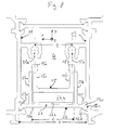
- EP08011031 The same applicant discloses a composite profile in which a connecting element 15 connects outer profile parts 11, 12 of the composite profile only in case of fire. This is below with reference to Fig. 8 described.
- An insulating web 23 connecting the outer profile parts 11, 12 has an insulating web body 23k extending in a longitudinal direction z and a width b in a transverse direction x perpendicular to the longitudinal direction z and a minimum thickness in a vertical direction y perpendicular to the longitudinal direction z and the transverse direction x has.
- connecting elements 23v for connecting the insulating web to the first and second outer profile parts 11, 12 are provided. The connection occurs e.g. by rolling into the recess 12c.
- the roll-in hammer 12e is pressed (rolled) in the direction of the abutment 12f and the connecting element is rolled in a known manner.
- guide walls 23a, 23b are provided parallel to each other and at a predetermined distance c of the mutually facing inner sides of the guide walls 23a, 23b which project from the insulating web body 23k in the height direction x.
- the guide walls 23a, 23b can also be formed continuously along the longitudinal direction z.
- the connecting element 15 has a U-shape in cross-section perpendicular to the longitudinal direction z, wherein the legs 15 s, 15 s of the U-shape extend parallel and along the longitudinal direction z. At the free end of the one leg 15s, a first engagement portion 15a is formed. On the other leg 15s, a correspondingly shaped second engagement portion 15b is formed. The first engagement portion 15a and the second engagement portion 15b are separated from each other in the transverse direction x.
- the outer profile part 11 has a projection on which a to the first engagement portion 15 a complementary engagement portion 11 a is provided. In an analogous manner is at the second Outer profile part 12, a projection having an engagement portion 12 b, which is complementary to the second engagement portion 15 b is formed.
- the outer profile part 11 is also connected via a conventional insulating web 24 with the outer profile part 12.
- the outer sides of the legs 15s of the connecting element 15 have a distance from each other, which corresponds to the distance c of the inner sides of the walls 23a and 23b of the insulating web 23 except for a necessary for a sliding mobility of the connecting element 15 between the walls 23a and 23b tolerance.
- the walls 23a and 23b which extend along the longitudinal direction z and parallel to each other, project perpendicular to the transverse direction x in a height direction y. This allows them to guide the outer profile member connector 15 with the necessary for a sliding movement tolerance during movement in the height direction y.
- the guide walls 23a and 23b form with the Isoliersteg stresses 23k a kind of longitudinal tub.
- an actuator 26 is disposed between the guide walls 23a and 23b.
- the actuator is formed in this embodiment by a self-adhesive tape having an epoxy-bonded intumescent layer 26a and a self-adhesive layer 26b.
- the actuator 26 has the form of a self-adhesive fire protection strip.
- the epoxy resin-bonded intumescent product contains thermally expanding components, flame retardants and additives. At a temperature of about 200 ° C, the epoxy-bound Intumeszenz apparatus begins to expand (froth) and achieved with appropriate heat exposure in case of fire up to a 20-fold increase in volume.
- the fire protection strip contains e.g. Water-releasing material through phase transition, so that additional cooling is achieved.
- a typical thickness is z. B. 5 mm, so that depending on the counterforce theoretically up to 100 mm travel can be achieved with this embodiment of the actuator 26.
- a corresponding increase in volume of the layer 26a causes the connecting element 15 in the height direction y is actively moved towards the engagement portion 11a and the engagement portion 12b. As also easily imagined, this results in movement of the first engagement portion 15a for engagement with the engagement portion 11a and active movement of the second engagement portion 15b for engagement with the engagement portion 12b.
- intumescent under heat other actuators such as bimetallic strips or other bimetallic elements, which bend under the action of heat and thus apply the force, conceivable.
- ausgasende under heat Ausgasende materials that are included in an actuator and then generate the actuating movement by the pneumatic effect of the exiting gas are conceivable, as well as other triggered by the heat actuators.
- Fig. 5 and Fig. 8 a modification of in Fig. 5 described embodiment.
- insulating strip 23 shown with the connecting element 15 and the actuator 26 instead of the insulating strip 13d Fig. 5 intended.
- the engagement portions 16a, 17a of the connection elements 16, 17 are analogous to those in Fig. 8 formed engaging portions 11a and 12b and aligned with the engaging portions 15a, 15b of the connecting element 15. It is obvious that the shapes of the respective engaging portions are interchangeable. In this way, also in the modification of in Fig. 5 shown embodiment, the previously described effect can be achieved.
- connecting elements 15 As an alternative to the S-shaped or U-shaped connecting elements 15 shown here, other shapes for the connecting elements 15 are also conceivable, for example a meander shape or a plurality of successive S-shaped sections.
- cooling intumescent product which can be used by an increase in volume at the same time as an actuator.
- the adapter elements designed as an adapter no change of conventional aluminum composite profile elements is necessary. Furthermore, the depth can be varied using different insulating webs, wherein the connecting elements are always the same design.
- the use of extrusion parts allows for easy production without reworking. In particular, the use of the connection elements allows the avoidance of an additional manufacturing effort at the manufacturer of the aluminum outer profile parts.
- a use of a push soft (eg from the DE 20 2007 016 649 U1 known) insulating web and at least one side push-soft engagement of the connecting element on the adapter allows a push soft composite of the composite profile.
- connection elements can be knurled. Furthermore, the connection elements may have a softer alloy than the outer profile parts. To further improve the connection between the connection elements and the outer profile parts and wires can be provided.
- the locking by the connecting element can also be done using aluminum brackets, sheet metal chambers, wire elements or truss components.
- the Kunststoffisolierstege may have a different shape of the connecting portion than a dovetail, e.g. Rectangles, polygonal shapes, etc.
- connection of the insulating webs with the connecting elements can be made variable.
- non-rollable Kunststoffisolierstege can be used for the composite profile. They can be connected in other ways than by rolling with the connection elements, for example by casting, gluing, extrusion, etc.
- connection of the connecting element with the connection elements can be made variable For example, by using a bonding method selected from snapping, curling, press-fitting, pinching, gluing, welding, bolting, riveting, or a combination thereof.
Landscapes
- Engineering & Computer Science (AREA)
- Civil Engineering (AREA)
- Structural Engineering (AREA)
- Special Wing (AREA)
Priority Applications (3)
| Application Number | Priority Date | Filing Date | Title |
|---|---|---|---|
| EP09013581A EP2317059B1 (fr) | 2009-10-28 | 2009-10-28 | Profil composite pour éléments de fenêtres, de porte ou de façades doté de propriétés ignifuges prédéfinies et connecteur et élément de raccordement correspondants |
| AT09013581T ATE554257T1 (de) | 2009-10-28 | 2009-10-28 | Verbundprofil für fenster-, türen- oder fassadenelemente mit vorbestimmten brandschutzeigenschaften und verbinder und anschlusselement dafür |
| PCT/EP2010/006562 WO2011050954A1 (fr) | 2009-10-28 | 2010-10-27 | Profil composite pour éléments de fenêtre, de porte ou de façade ayant des propriétés de résistance au feu prédéterminées, et connecteur et élément d'adaptateur pour un tel profil composite |
Applications Claiming Priority (1)
| Application Number | Priority Date | Filing Date | Title |
|---|---|---|---|
| EP09013581A EP2317059B1 (fr) | 2009-10-28 | 2009-10-28 | Profil composite pour éléments de fenêtres, de porte ou de façades doté de propriétés ignifuges prédéfinies et connecteur et élément de raccordement correspondants |
Publications (2)
| Publication Number | Publication Date |
|---|---|
| EP2317059A1 true EP2317059A1 (fr) | 2011-05-04 |
| EP2317059B1 EP2317059B1 (fr) | 2012-04-18 |
Family
ID=41694687
Family Applications (1)
| Application Number | Title | Priority Date | Filing Date |
|---|---|---|---|
| EP09013581A Active EP2317059B1 (fr) | 2009-10-28 | 2009-10-28 | Profil composite pour éléments de fenêtres, de porte ou de façades doté de propriétés ignifuges prédéfinies et connecteur et élément de raccordement correspondants |
Country Status (3)
| Country | Link |
|---|---|
| EP (1) | EP2317059B1 (fr) |
| AT (1) | ATE554257T1 (fr) |
| WO (1) | WO2011050954A1 (fr) |
Cited By (6)
| Publication number | Priority date | Publication date | Assignee | Title |
|---|---|---|---|---|
| US8176709B2 (en) * | 2008-06-18 | 2012-05-15 | Technoform Bautec Holding Gmbh | Composite profile for window, door or facade element |
| EP2487314A1 (fr) * | 2010-09-24 | 2012-08-15 | heroal- Johann Henkenjohann GmbH & Co. KG | Profil en métal léger pour façades, fenêtres, portes ou analogues |
| WO2016202438A1 (fr) * | 2015-06-15 | 2016-12-22 | Technoform Bautec Holding Gmbh | Élément isolant |
| DE102022120800A1 (de) * | 2022-08-17 | 2024-02-22 | Heroal - Johann Henkenjohann Gmbh & Co. Kg | Wärmegedämmtes Metallprofil mit Isolierstegen zum Verbinden zweier Profilelemente sowie Brückenstege zum Verbinden zweier Isolierstege |
| DE102023109418A1 (de) * | 2023-04-14 | 2024-10-17 | SCHÜCO International KG | Verbundprofil für Türen, Fenster oder Fassadenelemente und Verfahren zur Montage eines Verbundprofils |
| DE102023118982A1 (de) * | 2023-07-18 | 2025-01-23 | Heroal - Johann Henkenjohann Gmbh & Co. Kg | Profilanordnung mit Brandschutzeinsatz |
Families Citing this family (5)
| Publication number | Priority date | Publication date | Assignee | Title |
|---|---|---|---|---|
| DE102012010900B4 (de) * | 2012-06-01 | 2023-07-27 | Technoform Bautec Holding Gmbh | Verbundprofil für Fenster-, Türen oder Fassadenelemente und Isoliersteg für ein solches Verbundprofil |
| US9234380B2 (en) * | 2013-03-13 | 2016-01-12 | Technoform Bautec North America, Inc. | Thermally insulating composite frame apparatus with slide-in thermal isolator and method for making same |
| JP6158545B2 (ja) * | 2013-03-19 | 2017-07-05 | 三和シヤッター工業株式会社 | 窓シャッターの縦枠の防火構造 |
| JP6716248B2 (ja) * | 2015-12-25 | 2020-07-01 | 株式会社Lixil | 改装用建具 |
| JP2023182282A (ja) * | 2022-06-14 | 2023-12-26 | Ykk Ap株式会社 | 建具 |
Citations (10)
| Publication number | Priority date | Publication date | Assignee | Title |
|---|---|---|---|---|
| DE4404565C1 (de) | 1994-02-12 | 1995-05-18 | Wicona Bausysteme Gmbh | Wärmedämmendes Verbundprofil |
| DE4443762A1 (de) | 1994-12-08 | 1996-06-13 | Schueco Int Kg | Rahmenwerk aus Metallprofilen in Brandschutzausführung für Fenster, Türen, Fassaden oder Glasdächer |
| EP0785334A2 (fr) | 1992-09-26 | 1997-07-23 | TRUBE & KINGS KG | Elément de construction coupe-feu |
| EP1024243A2 (fr) | 1999-01-12 | 2000-08-02 | Pitscheider, Karl, Dr. | Connection resistante au feu avec âme isolante |
| EP1182317A2 (fr) | 2000-08-24 | 2002-02-27 | EVG Bauprofil-System Entwicklungs- und Vermarktungsgesellschaft mbH | Profilé thermiquement isolant pour constructions pare-feu |
| EP1327741A2 (fr) | 2002-01-15 | 2003-07-16 | Hörmann KG Eckelhausen | Système modulaire et procédé pour la fabrication d'un élément de construction coupe-feu ainsi que l'élément résultant |
| GB2413145A (en) * | 2004-04-17 | 2005-10-19 | Sapa Building Systems Ltd | Glazing frames |
| EP1607567A1 (fr) * | 2004-06-17 | 2005-12-21 | Reynaers Aluminium, naamloze vennootschap | Cadre coupe-feu pour fenêtre ou porte |
| DE202007015319U1 (de) * | 2007-11-05 | 2008-03-06 | Weikert Leichtmetallbau Gmbh | Isolator für Fenster-, Tür- und Fassadensysteme |
| DE202007016649U1 (de) | 2007-04-02 | 2008-04-30 | Technoform Caprano Und Brunnhofer Gmbh & Co. Kg | Leiterförmiger Isoliersteg für ein Verbundprofil für Fenster-, Türen- und Fassadenelemente und Verbundprofil für Fenster-, Türen- und Fassadenelemente |
Family Cites Families (1)
| Publication number | Priority date | Publication date | Assignee | Title |
|---|---|---|---|---|
| EP2136024B1 (fr) | 2008-06-18 | 2011-11-09 | Technoform Bautec Holding GmbH | Profilé composite pour élément de fenêtres, portes ou façades doté de propriétés ignifuges prédéfinies et isolateur pour un profilé composite doté de propriétés ignifuges |
-
2009
- 2009-10-28 AT AT09013581T patent/ATE554257T1/de active
- 2009-10-28 EP EP09013581A patent/EP2317059B1/fr active Active
-
2010
- 2010-10-27 WO PCT/EP2010/006562 patent/WO2011050954A1/fr not_active Ceased
Patent Citations (10)
| Publication number | Priority date | Publication date | Assignee | Title |
|---|---|---|---|---|
| EP0785334A2 (fr) | 1992-09-26 | 1997-07-23 | TRUBE & KINGS KG | Elément de construction coupe-feu |
| DE4404565C1 (de) | 1994-02-12 | 1995-05-18 | Wicona Bausysteme Gmbh | Wärmedämmendes Verbundprofil |
| DE4443762A1 (de) | 1994-12-08 | 1996-06-13 | Schueco Int Kg | Rahmenwerk aus Metallprofilen in Brandschutzausführung für Fenster, Türen, Fassaden oder Glasdächer |
| EP1024243A2 (fr) | 1999-01-12 | 2000-08-02 | Pitscheider, Karl, Dr. | Connection resistante au feu avec âme isolante |
| EP1182317A2 (fr) | 2000-08-24 | 2002-02-27 | EVG Bauprofil-System Entwicklungs- und Vermarktungsgesellschaft mbH | Profilé thermiquement isolant pour constructions pare-feu |
| EP1327741A2 (fr) | 2002-01-15 | 2003-07-16 | Hörmann KG Eckelhausen | Système modulaire et procédé pour la fabrication d'un élément de construction coupe-feu ainsi que l'élément résultant |
| GB2413145A (en) * | 2004-04-17 | 2005-10-19 | Sapa Building Systems Ltd | Glazing frames |
| EP1607567A1 (fr) * | 2004-06-17 | 2005-12-21 | Reynaers Aluminium, naamloze vennootschap | Cadre coupe-feu pour fenêtre ou porte |
| DE202007016649U1 (de) | 2007-04-02 | 2008-04-30 | Technoform Caprano Und Brunnhofer Gmbh & Co. Kg | Leiterförmiger Isoliersteg für ein Verbundprofil für Fenster-, Türen- und Fassadenelemente und Verbundprofil für Fenster-, Türen- und Fassadenelemente |
| DE202007015319U1 (de) * | 2007-11-05 | 2008-03-06 | Weikert Leichtmetallbau Gmbh | Isolator für Fenster-, Tür- und Fassadensysteme |
Cited By (6)
| Publication number | Priority date | Publication date | Assignee | Title |
|---|---|---|---|---|
| US8176709B2 (en) * | 2008-06-18 | 2012-05-15 | Technoform Bautec Holding Gmbh | Composite profile for window, door or facade element |
| EP2487314A1 (fr) * | 2010-09-24 | 2012-08-15 | heroal- Johann Henkenjohann GmbH & Co. KG | Profil en métal léger pour façades, fenêtres, portes ou analogues |
| WO2016202438A1 (fr) * | 2015-06-15 | 2016-12-22 | Technoform Bautec Holding Gmbh | Élément isolant |
| DE102022120800A1 (de) * | 2022-08-17 | 2024-02-22 | Heroal - Johann Henkenjohann Gmbh & Co. Kg | Wärmegedämmtes Metallprofil mit Isolierstegen zum Verbinden zweier Profilelemente sowie Brückenstege zum Verbinden zweier Isolierstege |
| DE102023109418A1 (de) * | 2023-04-14 | 2024-10-17 | SCHÜCO International KG | Verbundprofil für Türen, Fenster oder Fassadenelemente und Verfahren zur Montage eines Verbundprofils |
| DE102023118982A1 (de) * | 2023-07-18 | 2025-01-23 | Heroal - Johann Henkenjohann Gmbh & Co. Kg | Profilanordnung mit Brandschutzeinsatz |
Also Published As
| Publication number | Publication date |
|---|---|
| EP2317059B1 (fr) | 2012-04-18 |
| WO2011050954A1 (fr) | 2011-05-05 |
| ATE554257T1 (de) | 2012-05-15 |
Similar Documents
| Publication | Publication Date | Title |
|---|---|---|
| EP2317059B1 (fr) | Profil composite pour éléments de fenêtres, de porte ou de façades doté de propriétés ignifuges prédéfinies et connecteur et élément de raccordement correspondants | |
| EP2136024B1 (fr) | Profilé composite pour élément de fenêtres, portes ou façades doté de propriétés ignifuges prédéfinies et isolateur pour un profilé composite doté de propriétés ignifuges | |
| EP1024243B1 (fr) | Connection resistante au feu avec âme isolante | |
| DE202012010135U1 (de) | Isoliersteg für ein Verbundprofil für Fenster-, Türen- oder Fasadenelemente und Verbundprofil für Fenster-, Türen- oder Fassadenelemente mit Isoliersteg | |
| DE102014106226A1 (de) | Verbundprofil für Türen, Fenster oder Fassadenelemente | |
| DE202011101654U1 (de) | Thermisch getrenntes Profil | |
| DE102007020494B9 (de) | Paneel zum Bau einer Wand oder einer Decke eines Bauwerks | |
| DE10016012B4 (de) | Verbundprofil für Fenster, Fassaden, Türen oder Lichtdächer | |
| DE102008034055B4 (de) | Sicherheitsraum | |
| DE102010064034A1 (de) | Isolierstab für Verbundprofil von Bauelementen | |
| DE102015007611A1 (de) | Isolierelement | |
| EP2530230B1 (fr) | Isolateur pour cadres de fenêtre et de porte | |
| EP2781866B2 (fr) | Plaque murale pour une installation de séchage et procédé de fabrication de cette plaque murale | |
| WO2014005717A1 (fr) | Lame isolante pour un profilé composite pour éléments de fenêtre, de porte ou de façade et profilé composite pour éléments de fenêtre, de porte ou de façade muni d'une lame isolante | |
| EP1182317B1 (fr) | Profilé thermiquement isolant pour constructions pare-feu | |
| EP2157270B1 (fr) | Profilé calorifuge pour constructions ignifuges et profilé composite pour façades, fenêtres et portes | |
| DE102013112435A1 (de) | Verbundprofil und Verfahren zum Herstellen eines Verbundprofils | |
| EP2754834A1 (fr) | Baguette d'isolation thermique et profilé de cadre pour une fenêtre, une porte, une façade ou un toit vitré | |
| EP0646212B1 (fr) | Fermeture coupe-feu utilisee dans le domaine de la construction, notamment porte ou fenetre coupe-feu | |
| EP1932998A1 (fr) | Profil d'assemblage et procédé de fabrication d'un profil d'assemblage | |
| DE102016121068A1 (de) | Verbundprofil für eine Tür, ein Fenster oder ein Fassadenelement sowie Verfahren zur Herstellung des Verbundprofils | |
| EP2199519A1 (fr) | Profil composite protégé contre les incendies et procédé destiné à la fabrication d'un tel profil composite | |
| DE102023105033A1 (de) | Verbundprofil, Rahmen und Verfahren zur Herstellung des Verbundprofils | |
| EP4209640A1 (fr) | Profilé coupe-feu, élément de cellule de régulation de température de pièce doté de tels profilés coupe-feu et leur utilisation | |
| EP2942468B1 (fr) | Profilé composite pour des portes, fenêtres ou éléments de façade |
Legal Events
| Date | Code | Title | Description |
|---|---|---|---|
| PUAI | Public reference made under article 153(3) epc to a published international application that has entered the european phase |
Free format text: ORIGINAL CODE: 0009012 |
|
| 17P | Request for examination filed |
Effective date: 20110125 |
|
| AK | Designated contracting states |
Kind code of ref document: A1 Designated state(s): AT BE BG CH CY CZ DE DK EE ES FI FR GB GR HR HU IE IS IT LI LT LU LV MC MK MT NL NO PL PT RO SE SI SK SM TR |
|
| AX | Request for extension of the european patent |
Extension state: AL BA RS |
|
| RAP1 | Party data changed (applicant data changed or rights of an application transferred) |
Owner name: TECHNOFORM BAUTEC HOLDING GMBH |
|
| GRAP | Despatch of communication of intention to grant a patent |
Free format text: ORIGINAL CODE: EPIDOSNIGR1 |
|
| GRAS | Grant fee paid |
Free format text: ORIGINAL CODE: EPIDOSNIGR3 |
|
| GRAA | (expected) grant |
Free format text: ORIGINAL CODE: 0009210 |
|
| AK | Designated contracting states |
Kind code of ref document: B1 Designated state(s): AT BE BG CH CY CZ DE DK EE ES FI FR GB GR HR HU IE IS IT LI LT LU LV MC MK MT NL NO PL PT RO SE SI SK SM TR |
|
| REG | Reference to a national code |
Ref country code: GB Ref legal event code: FG4D Free format text: NOT ENGLISH |
|
| REG | Reference to a national code |
Ref country code: CH Ref legal event code: EP |
|
| REG | Reference to a national code |
Ref country code: IE Ref legal event code: FG4D Free format text: LANGUAGE OF EP DOCUMENT: GERMAN |
|
| REG | Reference to a national code |
Ref country code: AT Ref legal event code: REF Ref document number: 554257 Country of ref document: AT Kind code of ref document: T Effective date: 20120515 |
|
| REG | Reference to a national code |
Ref country code: DE Ref legal event code: R096 Ref document number: 502009003260 Country of ref document: DE Effective date: 20120614 |
|
| RAP2 | Party data changed (patent owner data changed or rights of a patent transferred) |
Owner name: TECHNOFORM BAUTEC HOLDING GMBH |
|
| REG | Reference to a national code |
Ref country code: DE Ref legal event code: R082 Ref document number: 502009003260 Country of ref document: DE Representative=s name: KRAMER - BARSKE - SCHMIDTCHEN, DE Effective date: 20120516 Ref country code: DE Ref legal event code: R081 Ref document number: 502009003260 Country of ref document: DE Owner name: TECHNOFORM BAUTEC HOLDING GMBH, DE Free format text: FORMER OWNER: TECHNOFORM BAUTEC HOLDING GMBH, 34277 FULDABRUECK, DE Effective date: 20120516 Ref country code: DE Ref legal event code: R082 Ref document number: 502009003260 Country of ref document: DE Representative=s name: KRAMER BARSKE SCHMIDTCHEN PATENTANWAELTE PARTG, DE Effective date: 20120516 |
|
| REG | Reference to a national code |
Ref country code: NL Ref legal event code: VDEP Effective date: 20120418 |
|
| LTIE | Lt: invalidation of european patent or patent extension |
Effective date: 20120418 |
|
| PG25 | Lapsed in a contracting state [announced via postgrant information from national office to epo] |
Ref country code: IS Free format text: LAPSE BECAUSE OF FAILURE TO SUBMIT A TRANSLATION OF THE DESCRIPTION OR TO PAY THE FEE WITHIN THE PRESCRIBED TIME-LIMIT Effective date: 20120818 Ref country code: PL Free format text: LAPSE BECAUSE OF FAILURE TO SUBMIT A TRANSLATION OF THE DESCRIPTION OR TO PAY THE FEE WITHIN THE PRESCRIBED TIME-LIMIT Effective date: 20120418 Ref country code: SE Free format text: LAPSE BECAUSE OF FAILURE TO SUBMIT A TRANSLATION OF THE DESCRIPTION OR TO PAY THE FEE WITHIN THE PRESCRIBED TIME-LIMIT Effective date: 20120418 Ref country code: CY Free format text: LAPSE BECAUSE OF FAILURE TO SUBMIT A TRANSLATION OF THE DESCRIPTION OR TO PAY THE FEE WITHIN THE PRESCRIBED TIME-LIMIT Effective date: 20120418 Ref country code: NO Free format text: LAPSE BECAUSE OF FAILURE TO SUBMIT A TRANSLATION OF THE DESCRIPTION OR TO PAY THE FEE WITHIN THE PRESCRIBED TIME-LIMIT Effective date: 20120718 Ref country code: FI Free format text: LAPSE BECAUSE OF FAILURE TO SUBMIT A TRANSLATION OF THE DESCRIPTION OR TO PAY THE FEE WITHIN THE PRESCRIBED TIME-LIMIT Effective date: 20120418 Ref country code: LT Free format text: LAPSE BECAUSE OF FAILURE TO SUBMIT A TRANSLATION OF THE DESCRIPTION OR TO PAY THE FEE WITHIN THE PRESCRIBED TIME-LIMIT Effective date: 20120418 |
|
| PG25 | Lapsed in a contracting state [announced via postgrant information from national office to epo] |
Ref country code: GR Free format text: LAPSE BECAUSE OF FAILURE TO SUBMIT A TRANSLATION OF THE DESCRIPTION OR TO PAY THE FEE WITHIN THE PRESCRIBED TIME-LIMIT Effective date: 20120719 Ref country code: LV Free format text: LAPSE BECAUSE OF FAILURE TO SUBMIT A TRANSLATION OF THE DESCRIPTION OR TO PAY THE FEE WITHIN THE PRESCRIBED TIME-LIMIT Effective date: 20120418 Ref country code: HR Free format text: LAPSE BECAUSE OF FAILURE TO SUBMIT A TRANSLATION OF THE DESCRIPTION OR TO PAY THE FEE WITHIN THE PRESCRIBED TIME-LIMIT Effective date: 20120418 Ref country code: SI Free format text: LAPSE BECAUSE OF FAILURE TO SUBMIT A TRANSLATION OF THE DESCRIPTION OR TO PAY THE FEE WITHIN THE PRESCRIBED TIME-LIMIT Effective date: 20120418 Ref country code: PT Free format text: LAPSE BECAUSE OF FAILURE TO SUBMIT A TRANSLATION OF THE DESCRIPTION OR TO PAY THE FEE WITHIN THE PRESCRIBED TIME-LIMIT Effective date: 20120820 |
|
| PG25 | Lapsed in a contracting state [announced via postgrant information from national office to epo] |
Ref country code: RO Free format text: LAPSE BECAUSE OF FAILURE TO SUBMIT A TRANSLATION OF THE DESCRIPTION OR TO PAY THE FEE WITHIN THE PRESCRIBED TIME-LIMIT Effective date: 20120418 Ref country code: DK Free format text: LAPSE BECAUSE OF FAILURE TO SUBMIT A TRANSLATION OF THE DESCRIPTION OR TO PAY THE FEE WITHIN THE PRESCRIBED TIME-LIMIT Effective date: 20120418 Ref country code: NL Free format text: LAPSE BECAUSE OF FAILURE TO SUBMIT A TRANSLATION OF THE DESCRIPTION OR TO PAY THE FEE WITHIN THE PRESCRIBED TIME-LIMIT Effective date: 20120418 Ref country code: SK Free format text: LAPSE BECAUSE OF FAILURE TO SUBMIT A TRANSLATION OF THE DESCRIPTION OR TO PAY THE FEE WITHIN THE PRESCRIBED TIME-LIMIT Effective date: 20120418 Ref country code: CZ Free format text: LAPSE BECAUSE OF FAILURE TO SUBMIT A TRANSLATION OF THE DESCRIPTION OR TO PAY THE FEE WITHIN THE PRESCRIBED TIME-LIMIT Effective date: 20120418 Ref country code: EE Free format text: LAPSE BECAUSE OF FAILURE TO SUBMIT A TRANSLATION OF THE DESCRIPTION OR TO PAY THE FEE WITHIN THE PRESCRIBED TIME-LIMIT Effective date: 20120418 |
|
| PLBE | No opposition filed within time limit |
Free format text: ORIGINAL CODE: 0009261 |
|
| STAA | Information on the status of an ep patent application or granted ep patent |
Free format text: STATUS: NO OPPOSITION FILED WITHIN TIME LIMIT |
|
| PG25 | Lapsed in a contracting state [announced via postgrant information from national office to epo] |
Ref country code: IT Free format text: LAPSE BECAUSE OF FAILURE TO SUBMIT A TRANSLATION OF THE DESCRIPTION OR TO PAY THE FEE WITHIN THE PRESCRIBED TIME-LIMIT Effective date: 20120418 |
|
| 26N | No opposition filed |
Effective date: 20130121 |
|
| BERE | Be: lapsed |
Owner name: TECHNOFORM BAUTEC HOLDING G.M.B.H. Effective date: 20121031 |
|
| PG25 | Lapsed in a contracting state [announced via postgrant information from national office to epo] |
Ref country code: ES Free format text: LAPSE BECAUSE OF FAILURE TO SUBMIT A TRANSLATION OF THE DESCRIPTION OR TO PAY THE FEE WITHIN THE PRESCRIBED TIME-LIMIT Effective date: 20120729 |
|
| REG | Reference to a national code |
Ref country code: DE Ref legal event code: R097 Ref document number: 502009003260 Country of ref document: DE Effective date: 20130121 |
|
| PG25 | Lapsed in a contracting state [announced via postgrant information from national office to epo] |
Ref country code: MC Free format text: LAPSE BECAUSE OF NON-PAYMENT OF DUE FEES Effective date: 20121031 |
|
| PG25 | Lapsed in a contracting state [announced via postgrant information from national office to epo] |
Ref country code: BG Free format text: LAPSE BECAUSE OF FAILURE TO SUBMIT A TRANSLATION OF THE DESCRIPTION OR TO PAY THE FEE WITHIN THE PRESCRIBED TIME-LIMIT Effective date: 20120718 Ref country code: BE Free format text: LAPSE BECAUSE OF NON-PAYMENT OF DUE FEES Effective date: 20121031 |
|
| REG | Reference to a national code |
Ref country code: IE Ref legal event code: MM4A |
|
| PG25 | Lapsed in a contracting state [announced via postgrant information from national office to epo] |
Ref country code: IE Free format text: LAPSE BECAUSE OF NON-PAYMENT OF DUE FEES Effective date: 20121028 |
|
| PG25 | Lapsed in a contracting state [announced via postgrant information from national office to epo] |
Ref country code: MT Free format text: LAPSE BECAUSE OF FAILURE TO SUBMIT A TRANSLATION OF THE DESCRIPTION OR TO PAY THE FEE WITHIN THE PRESCRIBED TIME-LIMIT Effective date: 20120418 |
|
| PG25 | Lapsed in a contracting state [announced via postgrant information from national office to epo] |
Ref country code: TR Free format text: LAPSE BECAUSE OF FAILURE TO SUBMIT A TRANSLATION OF THE DESCRIPTION OR TO PAY THE FEE WITHIN THE PRESCRIBED TIME-LIMIT Effective date: 20120418 |
|
| PG25 | Lapsed in a contracting state [announced via postgrant information from national office to epo] |
Ref country code: LU Free format text: LAPSE BECAUSE OF NON-PAYMENT OF DUE FEES Effective date: 20121028 Ref country code: SM Free format text: LAPSE BECAUSE OF FAILURE TO SUBMIT A TRANSLATION OF THE DESCRIPTION OR TO PAY THE FEE WITHIN THE PRESCRIBED TIME-LIMIT Effective date: 20120418 |
|
| REG | Reference to a national code |
Ref country code: CH Ref legal event code: PL |
|
| GBPC | Gb: european patent ceased through non-payment of renewal fee |
Effective date: 20131028 |
|
| PG25 | Lapsed in a contracting state [announced via postgrant information from national office to epo] |
Ref country code: LI Free format text: LAPSE BECAUSE OF NON-PAYMENT OF DUE FEES Effective date: 20131031 Ref country code: CH Free format text: LAPSE BECAUSE OF NON-PAYMENT OF DUE FEES Effective date: 20131031 Ref country code: GB Free format text: LAPSE BECAUSE OF NON-PAYMENT OF DUE FEES Effective date: 20131028 Ref country code: HU Free format text: LAPSE BECAUSE OF FAILURE TO SUBMIT A TRANSLATION OF THE DESCRIPTION OR TO PAY THE FEE WITHIN THE PRESCRIBED TIME-LIMIT Effective date: 20091028 |
|
| PG25 | Lapsed in a contracting state [announced via postgrant information from national office to epo] |
Ref country code: MK Free format text: LAPSE BECAUSE OF FAILURE TO SUBMIT A TRANSLATION OF THE DESCRIPTION OR TO PAY THE FEE WITHIN THE PRESCRIBED TIME-LIMIT Effective date: 20120418 |
|
| REG | Reference to a national code |
Ref country code: FR Ref legal event code: PLFP Year of fee payment: 7 |
|
| REG | Reference to a national code |
Ref country code: AT Ref legal event code: MM01 Ref document number: 554257 Country of ref document: AT Kind code of ref document: T Effective date: 20141028 |
|
| PG25 | Lapsed in a contracting state [announced via postgrant information from national office to epo] |
Ref country code: AT Free format text: LAPSE BECAUSE OF NON-PAYMENT OF DUE FEES Effective date: 20141028 |
|
| PGFP | Annual fee paid to national office [announced via postgrant information from national office to epo] |
Ref country code: FR Payment date: 20151026 Year of fee payment: 7 |
|
| REG | Reference to a national code |
Ref country code: FR Ref legal event code: ST Effective date: 20170630 |
|
| PG25 | Lapsed in a contracting state [announced via postgrant information from national office to epo] |
Ref country code: FR Free format text: LAPSE BECAUSE OF NON-PAYMENT OF DUE FEES Effective date: 20161102 |
|
| REG | Reference to a national code |
Ref country code: DE Ref legal event code: R081 Ref document number: 502009003260 Country of ref document: DE Owner name: TECHNOFORM BAUTEC HOLDING GMBH, DE Free format text: FORMER OWNER: TECHNOFORM BAUTEC HOLDING GMBH, 34117 KASSEL, DE |
|
| PGFP | Annual fee paid to national office [announced via postgrant information from national office to epo] |
Ref country code: DE Payment date: 20251020 Year of fee payment: 17 |