EP2317077A2 - Ailette optimisée - Google Patents
Ailette optimisée Download PDFInfo
- Publication number
- EP2317077A2 EP2317077A2 EP10188481A EP10188481A EP2317077A2 EP 2317077 A2 EP2317077 A2 EP 2317077A2 EP 10188481 A EP10188481 A EP 10188481A EP 10188481 A EP10188481 A EP 10188481A EP 2317077 A2 EP2317077 A2 EP 2317077A2
- Authority
- EP
- European Patent Office
- Prior art keywords
- airfoil
- blade
- turbine
- region
- working fluid
- Prior art date
- Legal status (The legal status is an assumption and is not a legal conclusion. Google has not performed a legal analysis and makes no representation as to the accuracy of the status listed.)
- Withdrawn
Links
- 230000010354 integration Effects 0.000 title 1
- 239000012530 fluid Substances 0.000 claims abstract description 31
- 238000002156 mixing Methods 0.000 claims description 8
- 239000000203 mixture Substances 0.000 claims description 3
- 238000009826 distribution Methods 0.000 abstract description 7
- 238000013461 design Methods 0.000 description 6
- 239000007789 gas Substances 0.000 description 6
- 238000007493 shaping process Methods 0.000 description 5
- 230000005465 channeling Effects 0.000 description 4
- 239000000567 combustion gas Substances 0.000 description 3
- 230000006872 improvement Effects 0.000 description 3
- 238000003754 machining Methods 0.000 description 2
- 238000012360 testing method Methods 0.000 description 2
- 230000001419 dependent effect Effects 0.000 description 1
- 230000000694 effects Effects 0.000 description 1
- 238000000605 extraction Methods 0.000 description 1
- 239000000446 fuel Substances 0.000 description 1
- 238000009434 installation Methods 0.000 description 1
- 238000005304 joining Methods 0.000 description 1
- 238000005259 measurement Methods 0.000 description 1
- 238000000034 method Methods 0.000 description 1
- 238000012986 modification Methods 0.000 description 1
- 230000004048 modification Effects 0.000 description 1
- 238000005457 optimization Methods 0.000 description 1
- 230000008569 process Effects 0.000 description 1
- 230000009467 reduction Effects 0.000 description 1
- 238000011160 research Methods 0.000 description 1
- 230000000717 retained effect Effects 0.000 description 1
- 238000011144 upstream manufacturing Methods 0.000 description 1
Images


Classifications
-
- F—MECHANICAL ENGINEERING; LIGHTING; HEATING; WEAPONS; BLASTING
- F01—MACHINES OR ENGINES IN GENERAL; ENGINE PLANTS IN GENERAL; STEAM ENGINES
- F01D—NON-POSITIVE DISPLACEMENT MACHINES OR ENGINES, e.g. STEAM TURBINES
- F01D5/00—Blades; Blade-carrying members; Heating, heat-insulating, cooling or antivibration means on the blades or the members
- F01D5/12—Blades
- F01D5/14—Form or construction
- F01D5/141—Shape, i.e. outer, aerodynamic form
-
- Y—GENERAL TAGGING OF NEW TECHNOLOGICAL DEVELOPMENTS; GENERAL TAGGING OF CROSS-SECTIONAL TECHNOLOGIES SPANNING OVER SEVERAL SECTIONS OF THE IPC; TECHNICAL SUBJECTS COVERED BY FORMER USPC CROSS-REFERENCE ART COLLECTIONS [XRACs] AND DIGESTS
- Y02—TECHNOLOGIES OR APPLICATIONS FOR MITIGATION OR ADAPTATION AGAINST CLIMATE CHANGE
- Y02T—CLIMATE CHANGE MITIGATION TECHNOLOGIES RELATED TO TRANSPORTATION
- Y02T50/00—Aeronautics or air transport
- Y02T50/60—Efficient propulsion technologies, e.g. for aircraft
Definitions
- the invention relates generally to turbine blades and to a turbine incorporating the blade. While the invention is primarily concerned with steam and gas turbines, it is also applicable to other turbines and compressors.
- turbine is used to include machines of this kind having airfoil blades.
- the invention is more specifically related to the interface of turbine airfoils with sidewalls for improving aerodynamic performance of the blade.
- Turbine efficiency is of great importance, particularly in large installations where a fractional increase in efficiency can produce very large cost savings. Considerable resources are continually expended into research on blade design as this is a critical component with respect to overall performance of the turbine.
- Turbine stages extract energy from the combustion gases to power the compressor, while also powering an upstream fan in a turbofan aircraft engine application, or powering an external drive shaft for marine and industrial applications.
- steam turbine steam is utilized to power the turbine stages.
- a turbine may include one or more stages of rotor blades and corresponding turbine nozzles.
- Each turbine nozzle includes a row of stator vanes having radially outer and inner sidewalls in the form of arcuate bands that support the vanes.
- the turbine rotor blades include airfoils integrally joined to radially inner sidewalls or platforms supported in turn by corresponding dovetails which mount the individual blades in dovetail slots formed in the perimeter of the supporting rotor disk.
- An annular shroud surrounds the radially outer tips of the rotor airfoils in each turbine stage.
- stator vanes and rotor blades have corresponding airfoils including generally concave pressure sides and generally convex suction sides extending axially in chord between opposite leading and trailing edges. Adjacent vanes and adjacent blades form corresponding flow passages therebetween bound by the radially inner and outer sidewalls.
- the working fluid flows axially downstream through the respective flow passages defined between the stator vanes and rotor blades.
- the aerodynamic contours of the vanes and blades, and corresponding flow passages therebetween, are precisely configured for maximizing energy extraction from the combustion gases which in turn rotate the rotor from which the blades extend.
- the complex three-dimensional (3D) configuration of the vane and blade airfoils is tailored for maximizing efficiency of operation, and varies radially in span along the airfoils as well as axially along the chords of the airfoils between the leading and trailing edges. Accordingly, the velocity and pressure distributions of the working fluid over the airfoil surfaces, as well as within the corresponding flow passages, also vary.
- the working fluid enters the corresponding rows of vanes and blades in the flow passages therebetween and is necessarily split at the respective leading edges of the airfoils.
- the locus of stagnation points of the incident working fluid extends along the leading edge of each airfoil, and corresponding boundary layers are formed along the pressure and suction sides of each airfoil, as well as along each radially outer and inner sidewall, which collectively bound the four sides of each flow passage.
- the local velocity of the working fluid varies from zero along the sidewalls and airfoil surfaces to the unrestrained velocity in the working fluid where the boundary layers terminate.
- the regions of the airfoil adjacent to the sidewalls are less adapted to local aerodynamic conditions and incur significantly greater losses compared to the main spans. Accordingly, there is a need to configure the regions of airfoils adjacent to the sidewalls to promote greater airfoil performance.
- the present invention relates to a design for turbine bucket or nozzle airfoils that accounts for the radial variation of inlet flow angle with the boundary layer of flow adjacent to the inner and outer sidewalls.
- a turbine stage includes a row of airfoils integrally joined to corresponding sidewalls and spaced laterally apart to define respective flow passages therebetween for channeling a working fluid.
- Each of the airfoils includes a concave pressure side and a laterally opposite convex suction side.
- the airfoils extend in chord between opposite leading and trailing edges.
- Each of the airfoils blends with the sidewalls in an arcuate fillet.
- a region of the airfoils in proximity to the corresponding sidewall and the associated arcuate fillet form a surface optimized according to a radial variation in inlet flow angle of the working fluid in proximity to the region.
- a turbine including a turbine casing; a rotor; a stator; and a row of airfoils.
- Each airfoil is integrally joined to corresponding sidewalls and spaced laterally apart to define respective flow passages therebetween for channeling a working fluid.
- Each airfoil may include a concave pressure side and a laterally opposite convex suction side, extending in chord between opposite leading and trailing edges.
- Each airfoil blends with the sidewalls in an arcuate fillet.
- a region of the airfoils, in proximity to the corresponding sidewall and the associated arcuate fillet forms a surface adapted to optimize airfoil performance according to a radial variation in inlet flow angle of the working fluid in proximity to the region.
- the following embodiments of the present invention have many advantages, including improvement of aerodynamic performance of the airfoil region for turbine nozzles and blades in proximity to the sidewalls, resulting in improvement in the turbine performance.
- FIG. 1 illustrates a simplified side view for series turbine stages 5 formed of nozzles and buckets.
- a working fluid 6 flows axially through nozzle 41 and bucket 42 of stage a first stage 10, through nozzle 51 and bucket 52 of second stage 20 and through nozzle 61 and bucket 62 of third stage 30. It should be recognized that the number of stages for a given turbine or compressor would vary with the size and application.
- FIG. 2 illustrates a top view of working fluid flow between the nozzle and bucket of one turbine stage, including an associated velocity triangle, at a selected radial location.
- the working fluid 101 passes through stationary nozzles 102 and is directed with a velocity V 105 in the direction of rotating blade 110.
- the blade 110 is rotating with absolute velocity W 111.
- Velocity triangle 120 shows vector value V 2 125, the velocity of the inlet steam relative to the rotating blade 110 as V 1 105-W 111.
- V 2 125 is also shown in relation to the blade 110.
- the profile of the turbine blade is carried out to optimize stage performance based in part on the inlet angle of the working fluid with respect to the blade. While the inlet angle of the working fluid with respect to the blade is relatively constant, it has been determined that significant variation of inlet angle for the working fluid is encountered in the region of the blade in proximity to the sidewalls.
- FIG. 3 illustrates test data for stage angle exit flow angle distribution 300 taken for a turbine stage.
- the ordinate provides a radial location of the measurement along the stage nozzle exit in percent.
- the abscissa provides a measured flow angle relative to axial in degrees.
- the rotating blade for the next turbine stage downstream from the nozzle assumes a stage entrance angle of about 20 degrees relative to axial.
- the flow angle 310 at the upper sidewall and the flow angle 320 at the lower sidewall are about 50 degrees relative to axial.
- the flow angle varies about 35 degrees over the bottom 5% of radial positioning near the hub and the flow angle varies about 30 degrees over the top 5% of radial positioning near the tip.
- FIG. 4 illustrates a prior art airfoil 400 that receives inlet working fluid flow 510 but includes no fillets or special shaping in the region of upper and lower sidewalls (not shown) to account for inlet angle deviations of the working fluid.
- FIG. 5 illustrates a prior art airfoil 110 that includes a concentric fillet.
- Prior art such as Haller et al. (US 5,906,474 ) has attempted to improve airfoil performance in the endwall regions by providing fillets with optimized radii.
- Haller the airfoils and their endwalls are formed integrally and machined to provide optimized fillets 150 between the blade surfaces and the endwalls with radii fixed as a proportion of throat dimension between adjacent blades.
- the fillets of Haller improve over endwall regions with no fillets, they have not addressed optimization of fillet shape to reduce the near-wall inlet flow direction losses that are described above.
- FIG. 6 illustrates an embodiment for an inventive fillet aligned to near-wall flow for a turbine blade.
- Turbine blade 600 includes illustrative axial-tangential profiles 610, 620, 630 and 640 for the blade airfoil and fillet at near wall heights descending from the airfoil proper 610 to the level of the sidewall 640.
- the profile of the fillet over the height range from the airfoil to the sidewall is optimized to the near-wall flow.
- Profile 620 is optimized to near-wall flow inlet 625 at a first radial height.
- Profile 630 is optimized to near-wall flow 635 at a second radial height.
- Profile 640 is optimized to near-wall flow 645 at the sidewall.
- computerized numerical machining permits continuous shaping of the near-wall interface of the airfoil and fillet with the sidewall to recognize inlet flow angle as a function of radial height. While the blended airfoil and fillet are optimally shaped about the leading edge 650, it may be seen that the blended profile may continue along one or both of the suction and pressure sides of the airfoil. The optimally shaped airfoil and filet in the end regions may taper into a single radius fillet along suction side 660 and pressure side 670.
- the shaping of the profiles at the different near-wall radial distances is generally most critical for airfoil efficiency in the area of the leading edge 650. For purposes of machining time and cost, therefore, it may be desirable to merge the radial distance-dependent profiles into a single optimized radius fillet 655, 656 for a downstream section 660, 670 of the airfoil.
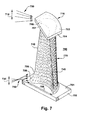
- FIG. 7 illustrates an embodiment of an inventive blade 700 that includes continuous shape variation from the airfoil to the sidewall 701 of platform 702 and to sidewall 703 of shroud 704 wherein the shape variation is optimized to enhance airfoil performance with respect to inlet flow angle of a working fluid.
- the shape of the airfoil end regions 707, 708 is integrated with the shape of the fillets 705, 706 joining airfoil 700 to the sidewalls.
- the inventive shaping is preferentially performed over a radial region 710 of the airfoil of about 10% in proximity to the tip 715 and a radial region 720 in proximity to the sidewall 701 at the hub platform 702, although a smaller radial region or a larger radial region may be so shaped.
- the upper radial region 710 of airfoil 700 may be optimally shaped for the radial distribution of inlet flow angles 750 in this upper region.
- the lower radial region 720 may be optimally shaped for the radial distribution of inlet flow angles 755 at the lower region.
- the shaping may be preferentially applied in the region of the leading edge 740 up to about halfway along chord length 760 on the leading edge and the trailing edge 745 of the airfoil.
- the invention as described above includes a design for turbine bucket or nozzle airfoils that accounts for the radial variation of inlet flow angle with the boundary layer of flow adjacent to the inner and outer sidewalls. This requires local chambering of the airfoil sections in the above regions with the primary objective of providing a continuous airfoil optimum entrance angle radial distribution. The prior art process for accomplishing this ignores the large deviation of inlet flow angle adjacent to the sidewalls, leading to the potential for higher energy losses in this already high loss region.
Landscapes
- Engineering & Computer Science (AREA)
- Physics & Mathematics (AREA)
- Fluid Mechanics (AREA)
- Mechanical Engineering (AREA)
- General Engineering & Computer Science (AREA)
- Turbine Rotor Nozzle Sealing (AREA)
- Structures Of Non-Positive Displacement Pumps (AREA)
Applications Claiming Priority (1)
| Application Number | Priority Date | Filing Date | Title |
|---|---|---|---|
| US12/607,371 US20110097205A1 (en) | 2009-10-28 | 2009-10-28 | Turbine airfoil-sidewall integration |
Publications (2)
| Publication Number | Publication Date |
|---|---|
| EP2317077A2 true EP2317077A2 (fr) | 2011-05-04 |
| EP2317077A3 EP2317077A3 (fr) | 2013-03-13 |
Family
ID=43242517
Family Applications (1)
| Application Number | Title | Priority Date | Filing Date |
|---|---|---|---|
| EP10188481A Withdrawn EP2317077A3 (fr) | 2009-10-28 | 2010-10-22 | Ailette optimisée |
Country Status (4)
| Country | Link |
|---|---|
| US (1) | US20110097205A1 (fr) |
| EP (1) | EP2317077A3 (fr) |
| JP (1) | JP2011094616A (fr) |
| CN (1) | CN102052091A (fr) |
Cited By (2)
| Publication number | Priority date | Publication date | Assignee | Title |
|---|---|---|---|---|
| WO2013103409A3 (fr) * | 2011-10-06 | 2013-09-06 | Siemens Energy, Inc. | Turbine à gaz ayant des angles d'éléments à profil aérodynamique optimisés |
| US10294796B2 (en) | 2013-08-23 | 2019-05-21 | Siemens Aktiengesellschaft | Blade or vane arrangement for a gas turbine engine |
Families Citing this family (7)
| Publication number | Priority date | Publication date | Assignee | Title |
|---|---|---|---|---|
| EP2505780B1 (fr) * | 2011-04-01 | 2016-05-11 | MTU Aero Engines GmbH | Agencement d'aubes pour une turbomachine |
| PL3022400T3 (pl) * | 2013-07-15 | 2024-04-22 | Rtx Corporation | Łopatki turbin o zmiennym zaokrągleniu |
| US10280757B2 (en) | 2013-10-31 | 2019-05-07 | United Technologies Corporation | Gas turbine engine airfoil with auxiliary flow channel |
| US8869504B1 (en) * | 2013-11-22 | 2014-10-28 | United Technologies Corporation | Geared turbofan engine gearbox arrangement |
| US9382801B2 (en) | 2014-02-26 | 2016-07-05 | General Electric Company | Method for removing a rotor bucket from a turbomachine rotor wheel |
| US20160160653A1 (en) * | 2014-12-08 | 2016-06-09 | Hyundai Motor Company | Turbine wheel for turbo charger |
| JP6617837B2 (ja) | 2016-11-10 | 2019-12-11 | 株式会社Ihi | 可変ノズルユニットおよび過給機 |
Citations (1)
| Publication number | Priority date | Publication date | Assignee | Title |
|---|---|---|---|---|
| US5906474A (en) | 1994-08-30 | 1999-05-25 | Gec Alsthom Limited | Turbine blade |
Family Cites Families (10)
| Publication number | Priority date | Publication date | Assignee | Title |
|---|---|---|---|---|
| JP2000045704A (ja) * | 1998-07-31 | 2000-02-15 | Toshiba Corp | 蒸気タービン |
| US6419446B1 (en) * | 1999-08-05 | 2002-07-16 | United Technologies Corporation | Apparatus and method for inhibiting radial transfer of core gas flow within a core gas flow path of a gas turbine engine |
| US6969232B2 (en) * | 2002-10-23 | 2005-11-29 | United Technologies Corporation | Flow directing device |
| US6921246B2 (en) * | 2002-12-20 | 2005-07-26 | General Electric Company | Methods and apparatus for assembling gas turbine nozzles |
| US6857853B1 (en) * | 2003-08-13 | 2005-02-22 | General Electric Company | Conical tip shroud fillet for a turbine bucket |
| JP4346412B2 (ja) * | 2003-10-31 | 2009-10-21 | 株式会社東芝 | タービン翼列装置 |
| US7217096B2 (en) * | 2004-12-13 | 2007-05-15 | General Electric Company | Fillet energized turbine stage |
| US7249933B2 (en) * | 2005-01-10 | 2007-07-31 | General Electric Company | Funnel fillet turbine stage |
| US7220100B2 (en) * | 2005-04-14 | 2007-05-22 | General Electric Company | Crescentic ramp turbine stage |
| US7371046B2 (en) * | 2005-06-06 | 2008-05-13 | General Electric Company | Turbine airfoil with variable and compound fillet |
-
2009
- 2009-10-28 US US12/607,371 patent/US20110097205A1/en not_active Abandoned
-
2010
- 2010-10-22 EP EP10188481A patent/EP2317077A3/fr not_active Withdrawn
- 2010-10-22 JP JP2010236944A patent/JP2011094616A/ja not_active Withdrawn
- 2010-10-28 CN CN2010105395201A patent/CN102052091A/zh active Pending
Patent Citations (1)
| Publication number | Priority date | Publication date | Assignee | Title |
|---|---|---|---|---|
| US5906474A (en) | 1994-08-30 | 1999-05-25 | Gec Alsthom Limited | Turbine blade |
Cited By (3)
| Publication number | Priority date | Publication date | Assignee | Title |
|---|---|---|---|---|
| WO2013103409A3 (fr) * | 2011-10-06 | 2013-09-06 | Siemens Energy, Inc. | Turbine à gaz ayant des angles d'éléments à profil aérodynamique optimisés |
| US8864457B2 (en) | 2011-10-06 | 2014-10-21 | Siemens Energy, Inc. | Gas turbine with optimized airfoil element angles |
| US10294796B2 (en) | 2013-08-23 | 2019-05-21 | Siemens Aktiengesellschaft | Blade or vane arrangement for a gas turbine engine |
Also Published As
| Publication number | Publication date |
|---|---|
| EP2317077A3 (fr) | 2013-03-13 |
| US20110097205A1 (en) | 2011-04-28 |
| JP2011094616A (ja) | 2011-05-12 |
| CN102052091A (zh) | 2011-05-11 |
Similar Documents
| Publication | Publication Date | Title |
|---|---|---|
| EP2317077A2 (fr) | Ailette optimisée | |
| US7220100B2 (en) | Crescentic ramp turbine stage | |
| US9074483B2 (en) | High camber stator vane | |
| US10408072B2 (en) | Turbine nozzle airfoil profile | |
| EP2959108B1 (fr) | Turbine à gaz ayant un étage désaccordé | |
| EP1669544B1 (fr) | Etage de turbine avec contour de raccordement refroidi par couche d'air | |
| US11125089B2 (en) | Turbine incorporating endwall fences | |
| US10344601B2 (en) | Contoured flowpath surface | |
| EP1674659B1 (fr) | Aubage statorique ayant un dénivelé abaissé arrondi de plate-forme | |
| US10533440B2 (en) | Turbine nozzle airfoil profile | |
| EP3032033B2 (fr) | Ensemble de vanne pour moteur de turbine à gaz | |
| US20130089415A1 (en) | Gas turbine with optimized airfoil element angles | |
| US11149552B2 (en) | Shroud for splitter and rotor airfoils of a fan for a gas turbine engine | |
| JP2008248701A (ja) | ターボ機械の壁、及びターボ機械 | |
| US10415406B2 (en) | Turbine nozzle airfoil profile | |
| US10689993B2 (en) | Airfoil shape for turbine nozzles | |
| CN116753036A (zh) | 具有高加速度和低叶片转动的翼型件的涡轮发动机 | |
| US10280774B2 (en) | Turbine nozzle airfoil profile | |
| US11306735B2 (en) | Turbine nozzle airfoil profile | |
| EP3740656B1 (fr) | Article de fabrication | |
| US20200131911A1 (en) | Airfoil shape for turbine nozzles | |
| EP3358134B1 (fr) | Turbine à vapeur avec aube rotorique | |
| US20250283415A1 (en) | Turbine engine with a blade assembly having a set of cooling conduits | |
| Lee et al. | Crescentic ramp turbine stage | |
| JP2007009761A (ja) | 軸流タービン |
Legal Events
| Date | Code | Title | Description |
|---|---|---|---|
| PUAI | Public reference made under article 153(3) epc to a published international application that has entered the european phase |
Free format text: ORIGINAL CODE: 0009012 |
|
| AK | Designated contracting states |
Kind code of ref document: A2 Designated state(s): AL AT BE BG CH CY CZ DE DK EE ES FI FR GB GR HR HU IE IS IT LI LT LU LV MC MK MT NL NO PL PT RO RS SE SI SK SM TR |
|
| AX | Request for extension of the european patent |
Extension state: BA ME |
|
| PUAL | Search report despatched |
Free format text: ORIGINAL CODE: 0009013 |
|
| AK | Designated contracting states |
Kind code of ref document: A3 Designated state(s): AL AT BE BG CH CY CZ DE DK EE ES FI FR GB GR HR HU IE IS IT LI LT LU LV MC MK MT NL NO PL PT RO RS SE SI SK SM TR |
|
| AX | Request for extension of the european patent |
Extension state: BA ME |
|
| RIC1 | Information provided on ipc code assigned before grant |
Ipc: F01D 5/14 20060101AFI20130204BHEP |
|
| STAA | Information on the status of an ep patent application or granted ep patent |
Free format text: STATUS: THE APPLICATION IS DEEMED TO BE WITHDRAWN |
|
| 18D | Application deemed to be withdrawn |
Effective date: 20130914 |