EP2317832A2 - Boîtier - Google Patents
Boîtier Download PDFInfo
- Publication number
- EP2317832A2 EP2317832A2 EP10014070A EP10014070A EP2317832A2 EP 2317832 A2 EP2317832 A2 EP 2317832A2 EP 10014070 A EP10014070 A EP 10014070A EP 10014070 A EP10014070 A EP 10014070A EP 2317832 A2 EP2317832 A2 EP 2317832A2
- Authority
- EP
- European Patent Office
- Prior art keywords
- housing
- clamping
- housing according
- edge region
- wall
- Prior art date
- Legal status (The legal status is an assumption and is not a legal conclusion. Google has not performed a legal analysis and makes no representation as to the accuracy of the status listed.)
- Withdrawn
Links
Images
Classifications
-
- H—ELECTRICITY
- H05—ELECTRIC TECHNIQUES NOT OTHERWISE PROVIDED FOR
- H05K—PRINTED CIRCUITS; CASINGS OR CONSTRUCTIONAL DETAILS OF ELECTRIC APPARATUS; MANUFACTURE OF ASSEMBLAGES OF ELECTRICAL COMPONENTS
- H05K5/00—Casings, cabinets or drawers for electric apparatus
- H05K5/10—Casings, cabinets or drawers for electric apparatus comprising several parts forming a closed casing
- H05K5/15—Casings, cabinets or drawers for electric apparatus comprising several parts forming a closed casing assembled by resilient members
-
- H—ELECTRICITY
- H05—ELECTRIC TECHNIQUES NOT OTHERWISE PROVIDED FOR
- H05K—PRINTED CIRCUITS; CASINGS OR CONSTRUCTIONAL DETAILS OF ELECTRIC APPARATUS; MANUFACTURE OF ASSEMBLAGES OF ELECTRICAL COMPONENTS
- H05K5/00—Casings, cabinets or drawers for electric apparatus
- H05K5/02—Details
- H05K5/0217—Mechanical details of casings
- H05K5/0221—Locks; Latches
-
- H—ELECTRICITY
- H05—ELECTRIC TECHNIQUES NOT OTHERWISE PROVIDED FOR
- H05K—PRINTED CIRCUITS; CASINGS OR CONSTRUCTIONAL DETAILS OF ELECTRIC APPARATUS; MANUFACTURE OF ASSEMBLAGES OF ELECTRICAL COMPONENTS
- H05K5/00—Casings, cabinets or drawers for electric apparatus
- H05K5/02—Details
- H05K5/0217—Mechanical details of casings
- H05K5/0226—Hinges
Definitions
- the invention relates to a housing which is particularly suitable for receiving electrical or electronic components or displays.
- a lid, a wall part or a side wall of the housing In order to perform installation and maintenance in a housing, a lid, a wall part or a side wall of the housing must be opened and then closed again, which is usually associated with the loosening and re-tightening of numerous mounting screws. This is both structurally complex and time-consuming.
- the invention has for its object to improve a housing to the effect that the opening and closing operation of a housing wall or a wall part takes less time and is structurally simplified.
- a housing with a rectilinear edge region and a clamping element that is pivotally mounted about a parallel to the edge region extending pivot axis, arranged at a distance and parallel to the pivot axis An horrelement by a clamping element in Direction of a clamping position is pivotable, wherein a removable housing wall between a extending from the edge region abutment region and the pressure element is clamped fixable.
- edge region adjacent to an upper, lower, front, rear and / or side wall of the housing can be provided that the edge region adjacent to an upper, lower, front, rear and / or side wall of the housing.
- the removable housing wall may be an upper, lower, front, back or side wall or a part thereof.
- the removable housing wall can be held by two, three or four clamping elements.
- the pivot axis is arranged at a distance from an extension plane or the extension planes of one or both of the edge region extending housing edge or housing walls.
- the clamping element may have a first leg, on which the pressing element is arranged, and a second leg bent away therefrom, on which the pivot axis is arranged.
- the clamping means may be formed as a screw, spring, clamping lever or the like, it being advantageous if the clamping means is designed as a clamping screw and acts between the first or second leg of the clamping element and a housing wall. It is advantageous if the clamping screw cooperates with the second leg and is deliverable from the outside against a housing wall.
- the pressure element is elastic.
- the contact element can be provided with a sealing element.
- the edge region is formed from extruded material, such as plastic or aluminum. Furthermore, it can be provided that the clamping element is formed from extruded material.
- the pivot axis may be formed by a profile thickening with a circular cross-section and a cooperating open channel-shaped profile region with a corresponding circular free cross-section.
- clamping element and edge region may be arranged a raising spring, for example in the form of a leaf spring.
- the housing has a plurality of removable housing walls to be held with clamping elements.
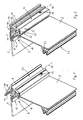
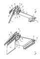
- Fig. 1 to 4 show perspective views of a housing cutout in different directions, wherein a side wall 2 and an edge portion 4 are shown.
- the edge region 4 forms a right-angled transition in this case from the side wall 2 to a front side of the housing, which in the illustrated example is essentially formed by a front plate 6.
- the front plate 6 is detachably held on the edge region 4 by means of a clamping element 8.
- the clamping element 8 is pivotably held about an axis parallel to the edge region 4 extending pivot axis 10 and between an open position ( Fig.1 . 3 and 4 ) and a closed clamping position ( Fig. 2 ) movable.
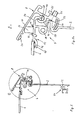
- the edge region 4 essentially forms the transition between the side wall 2 and the front or front wall formed by the front plate 6 and has in the illustrated example, the pivot axis 10 and an element thereof and a contact area 12, between which and the clamping element 8 the Front panel 6 is to hold. Furthermore, the edge region 4 is provided with a screw 14 in order to mount more side walls, edge elements or the like can.
- the clamping element 8 has a first leg 18 on which an elastic pressure element 20 is held, and a second leg 22 which forms the pivot axis 10 together with an angled projection 24 of the edge portion 4.
- the clamping element 8 is provided with at least one clamping means, which is realized in the illustrated example by a clamping screw forming a threaded pin 26 which engages in a threaded bore in the second leg 22 and cooperates with a stop surface 28 at the edge of the edge portion 4 in the Near the transition to the side wall 2 is arranged.
- the stop surface 28 is arranged at a distance from the plane of extent of the side wall 2 and in the vicinity of the pivot axis 10.
- both the edge region 4 and the clamping element 8 have a radially around the pivot axis 10 gradients of the wall piece 30, 32, wherein the wall pieces are at a small radial distance from each other and a covering function with respect to the gap between Edge region 4 and second leg 22 of the clamping element and thus also the pivot axis 10, the threaded pin 26 and the stop surface 28 have outwardly.
- a leaf spring 34 is held on the edge portion 4 and acts between this and the first leg 18 of the clamping element 8 in the opening direction, so that the clamping element 8 by means of the threaded pin 26 against the spring force of the leaf spring in the closed position or clamping position Fig. 2 can be brought.
- the side wall 2 and the edge portion 4 are integrally made as extruded plastic or light metal, and also the clamping element 8 is made of a comparable material as an extrusion.
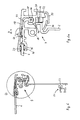
- This has manufacturing technology the advantage that the pivot axis 10 in a simple manner by a profile thickening 38 with a circular cross-section, which sits on an angled wall piece 40, and an open, channel-shaped profile region 42 can be formed with a corresponding circular free cross-section.
- the screw 14 and the displaced from the plane of extension of the side wall 2 stop surface 28 can be formed in a simple manner by appropriate design of the course of the wall.
- the leaf spring 34 is held behind two hook-shaped profile projections 44.
- the contact region 12 is likewise formed in one piece with the edge region 4 and has a channel-shaped recess 46 for receiving an elastic sealing element 48.
- side walls of the housing may connect perpendicular to the side wall 2 and perpendicular to the pivot axis 10, wherein the already mentioned screw 14 and another, in an edge region. 4 opposite edge region 50 arranged screw 52 can serve for screwing.
- Another housing wall for example a rear wall, can connect to the further edge region 50 parallel to the front plate 6.
- the clamping element 8 Due to the production of the clamping element 8 and the edge portion 4 or the entire side wall 2 as an extruded profile, the clamping element 8, after it has been reached to the required length, be slid along the pivot axis 10 on the profile thickening 38 of the edge portion and is for a suitable lateral Fixation, recordable by edge elements or side panels, held inextricably on the side wall 2.
- the clamping element 8 By rotation of the threaded pin 26 in one or the other direction, the clamping element 8 can first be brought by the force of the leaf spring 34 in the open position in which the front panel 6 can be inserted, and then in the closed or clamping position Fig.2 or 6 in that the clamping element clamps the front panel between its first leg 18 and the contact area 12 of the edge area 4.
- edge region and clamping element are made of aluminum, they have a high strength and rigidity, so that a single set screw 26 is sufficient for not too large housing widths.
- the pivot axis 10 is integrally formed on the edge portion 4, it can be provided that the pivot axis is detachable with respect to.
- the edge portion 4 and is secured thereto, for example by means of fastening screws.
- a single clamping element 8 is sufficient for secure fixing of a housing wall such as the front plate 6, in particular if this is inserted positively, for example, on an opposite edge behind a retaining projection, it can be provided that a housing wall is held by a plurality of clamping elements, for example, two, three or four clamping elements.
Landscapes
- Engineering & Computer Science (AREA)
- Microelectronics & Electronic Packaging (AREA)
- Clamps And Clips (AREA)
- Soil Working Implements (AREA)
- Casings For Electric Apparatus (AREA)
Applications Claiming Priority (1)
| Application Number | Priority Date | Filing Date | Title |
|---|---|---|---|
| DE202009014800U DE202009014800U1 (de) | 2009-11-03 | 2009-11-03 | Gehäuse |
Publications (2)
| Publication Number | Publication Date |
|---|---|
| EP2317832A2 true EP2317832A2 (fr) | 2011-05-04 |
| EP2317832A3 EP2317832A3 (fr) | 2017-04-26 |
Family
ID=41694222
Family Applications (1)
| Application Number | Title | Priority Date | Filing Date |
|---|---|---|---|
| EP10014070.6A Withdrawn EP2317832A3 (fr) | 2009-11-03 | 2010-10-28 | Boîtier |
Country Status (2)
| Country | Link |
|---|---|
| EP (1) | EP2317832A3 (fr) |
| DE (1) | DE202009014800U1 (fr) |
Cited By (1)
| Publication number | Priority date | Publication date | Assignee | Title |
|---|---|---|---|---|
| EP2587901A3 (fr) * | 2011-10-24 | 2017-11-15 | bopla Gehäuse Systeme GmbH | Boîtier avec une partie inférieure et un couvercle |
Family Cites Families (4)
| Publication number | Priority date | Publication date | Assignee | Title |
|---|---|---|---|---|
| US3088560A (en) * | 1960-06-03 | 1963-05-07 | Storkline Corp | Cabinet construction |
| IT1067054B (it) * | 1976-07-06 | 1985-03-12 | Gewiss Spa | Cassetta a pannelli per componenti elettrici |
| US6742365B1 (en) * | 2002-11-19 | 2004-06-01 | Mcgard, Inc. | Ringless meter lock |
| DE202007007141U1 (de) * | 2007-05-18 | 2007-09-13 | Heidenreich Gehäusetechnik GmbH & Co. KG | Profil für ein Gehäuse |
-
2009
- 2009-11-03 DE DE202009014800U patent/DE202009014800U1/de not_active Expired - Lifetime
-
2010
- 2010-10-28 EP EP10014070.6A patent/EP2317832A3/fr not_active Withdrawn
Cited By (1)
| Publication number | Priority date | Publication date | Assignee | Title |
|---|---|---|---|---|
| EP2587901A3 (fr) * | 2011-10-24 | 2017-11-15 | bopla Gehäuse Systeme GmbH | Boîtier avec une partie inférieure et un couvercle |
Also Published As
| Publication number | Publication date |
|---|---|
| EP2317832A3 (fr) | 2017-04-26 |
| DE202009014800U1 (de) | 2010-02-18 |
Similar Documents
| Publication | Publication Date | Title |
|---|---|---|
| EP2184428B1 (fr) | Charnière de porte pour arrangement caché | |
| DE4317564C2 (de) | Türöffner mit einer verriegelbaren, schwenkbaren Falle | |
| WO2016095915A1 (fr) | Ventilateur axial | |
| EP1582675A1 (fr) | Dispositif pour le montage des charnières sur le cadre des portes | |
| EP2876366B1 (fr) | Lampe avec élément de serrage | |
| DE102005000020B4 (de) | Anordnung zur Halterung eines Installationsgeräte-Einsatzes an einer Tragplatte | |
| EP2317832A2 (fr) | Boîtier | |
| EP2407062B1 (fr) | Dispositif de retenue | |
| EP2270302A2 (fr) | Dispositif de transmission de force pour une installation de porte | |
| DE102017203740B4 (de) | Luftausströmeranordnung | |
| EP2578891B1 (fr) | Adapteur | |
| EP1344478B1 (fr) | Cabine de douche avec au moins une cloison de verre | |
| EP1662627A1 (fr) | Dispositif pour la fixation détachable d'un boîtier d'appareil à un rail profilé | |
| EP4036359B1 (fr) | Support de parement, parement supérieur pour une porte, ainsi que porte pourvue de parement supérieur | |
| DE29905418U1 (de) | Vorrichtung zur lösbaren Befestigung einer Gebäudeplatte | |
| DE2432961A1 (de) | Vorrichtung zur befestigung eines lagerstuecks fuer eine ganzglastuer | |
| DE102023200097A1 (de) | Befestigungsanordnung zum Befestigen einer Dusch- oder Trennwand an einer Wand und Verfahren zum Befestigen einer Dusch- oder Trennwand an einer Wand | |
| EP0005752B1 (fr) | Canal pour une conduite d'électricité et/ou de gaz et méthode de montage de la plaque amovible de fermeture | |
| DE29504527U1 (de) | Rückwandriegel für Möbel wie Schränke o.dgl. | |
| DE102017200514B4 (de) | Befestigungselement zur Festlegung eines Türantriebs an einer Profilschiene | |
| DE202004013314U1 (de) | Vorrichtung zum Befestigen von Storen sowie ein dafür geeignetes Storengehäuse und ein Haltebügel | |
| EP2065521B1 (fr) | Dispositif de fixation pour monter un apparail dans un trou de montage dans une plaque de support | |
| DE102023201826A1 (de) | Schraubverbindung | |
| EP2434072B1 (fr) | Dispositif d'aide de fixation d'éléments de profilé sur les bords d'une ouverture de montage | |
| DE202006000312U1 (de) | Glasplatten-Befestigungsaufbau |
Legal Events
| Date | Code | Title | Description |
|---|---|---|---|
| PUAI | Public reference made under article 153(3) epc to a published international application that has entered the european phase |
Free format text: ORIGINAL CODE: 0009012 |
|
| AK | Designated contracting states |
Kind code of ref document: A2 Designated state(s): AL AT BE BG CH CY CZ DE DK EE ES FI FR GB GR HR HU IE IS IT LI LT LU LV MC MK MT NL NO PL PT RO RS SE SI SK SM TR |
|
| AX | Request for extension of the european patent |
Extension state: BA ME |
|
| PUAL | Search report despatched |
Free format text: ORIGINAL CODE: 0009013 |
|
| AK | Designated contracting states |
Kind code of ref document: A3 Designated state(s): AL AT BE BG CH CY CZ DE DK EE ES FI FR GB GR HR HU IE IS IT LI LT LU LV MC MK MT NL NO PL PT RO RS SE SI SK SM TR |
|
| AX | Request for extension of the european patent |
Extension state: BA ME |
|
| RIC1 | Information provided on ipc code assigned before grant |
Ipc: H05K 5/02 20060101ALI20170323BHEP Ipc: H05K 5/00 20060101AFI20170323BHEP |
|
| STAA | Information on the status of an ep patent application or granted ep patent |
Free format text: STATUS: THE APPLICATION IS DEEMED TO BE WITHDRAWN |
|
| 18D | Application deemed to be withdrawn |
Effective date: 20171027 |