EP2317836B1 - Filterdeckelanordnung - Google Patents
Filterdeckelanordnung Download PDFInfo
- Publication number
- EP2317836B1 EP2317836B1 EP09789185.7A EP09789185A EP2317836B1 EP 2317836 B1 EP2317836 B1 EP 2317836B1 EP 09789185 A EP09789185 A EP 09789185A EP 2317836 B1 EP2317836 B1 EP 2317836B1
- Authority
- EP
- European Patent Office
- Prior art keywords
- filter
- retainer
- bonnet
- top assembly
- cage bottom
- Prior art date
- Legal status (The legal status is an assumption and is not a legal conclusion. Google has not performed a legal analysis and makes no representation as to the accuracy of the status listed.)
- Active
Links
- 230000002093 peripheral effect Effects 0.000 claims description 4
- 241001465754 Metazoa Species 0.000 description 14
- 239000002184 metal Substances 0.000 description 7
- 229920003023 plastic Polymers 0.000 description 5
- 239000004033 plastic Substances 0.000 description 5
- 238000004519 manufacturing process Methods 0.000 description 4
- 239000000463 material Substances 0.000 description 4
- 238000000034 method Methods 0.000 description 4
- 230000001055 chewing effect Effects 0.000 description 2
- 230000009467 reduction Effects 0.000 description 2
- 241000699666 Mus <mouse, genus> Species 0.000 description 1
- 241000699670 Mus sp. Species 0.000 description 1
- 241000283984 Rodentia Species 0.000 description 1
- 238000010171 animal model Methods 0.000 description 1
- 230000000712 assembly Effects 0.000 description 1
- 238000000429 assembly Methods 0.000 description 1
- 230000009286 beneficial effect Effects 0.000 description 1
- 210000000078 claw Anatomy 0.000 description 1
- 230000001419 dependent effect Effects 0.000 description 1
- 230000003670 easy-to-clean Effects 0.000 description 1
- 238000001914 filtration Methods 0.000 description 1
- 230000003993 interaction Effects 0.000 description 1
- 230000007246 mechanism Effects 0.000 description 1
- 230000008520 organization Effects 0.000 description 1
- 229920000728 polyester Polymers 0.000 description 1
- 230000008569 process Effects 0.000 description 1
- 239000012858 resilient material Substances 0.000 description 1
- 230000003068 static effect Effects 0.000 description 1
Images





Classifications
-
- A—HUMAN NECESSITIES
- A01—AGRICULTURE; FORESTRY; ANIMAL HUSBANDRY; HUNTING; TRAPPING; FISHING
- A01K—ANIMAL HUSBANDRY; AVICULTURE; APICULTURE; PISCICULTURE; FISHING; REARING OR BREEDING ANIMALS, NOT OTHERWISE PROVIDED FOR; NEW BREEDS OF ANIMALS
- A01K1/00—Housing animals; Equipment therefor
- A01K1/02—Pigsties; Dog-kennels; Rabbit-hutches or the like
- A01K1/03—Housing for domestic or laboratory animals
- A01K1/031—Cages for laboratory animals; Cages for measuring metabolism of animals
Definitions
- This invention relates generally to a filter top assembly for a rodent cage which may be used as a static unit or in connection with a ventilated cage and rack system and particularly to a bonnet that is configured to protect filter paper supported thereby.
- the cages must provide the flow of air in and out of the cage, and can include a filter top through which air can enter or exit the cage.
- a filter paper can be provided to filter the air entering or exiting the cage.
- EP 1 461 997 A2 discloses a bonnet for covering a cage bottom, wherein the bonnet comprises a top for covering the top rim of the cage bottom.
- the top has a skirt descending from the perimeter.
- a filter is disposed on the top for filtering air entering the cage bottom.
- a filter retainer rests on the filter top and is disposed above the filter.
- a preferred embodiment of the present invention is directed to a filter top assembly according to claim 1. Preferred embodiments are disclosed in the dependent claims. It is an object of the invention to provide an improved filter top assembly for an animal cage. Another object of the invention is to provide an improved bonnet for an animal cage which includes protection for a filter. Other objects, features, and characteristics of the present invention, as well as the methods of operation and functions of the related elements of the structure, and the combination of parts and economies of manufacture, will become more apparent upon consideration of the following detailed description with reference to the accompanying drawings, all of which form a part of this specification.
- FIG. 1 an embodiment of a cage assembly 1 is shown, including a cage bottom 10 and a filter top assembly 20.
- An embodiment of cage bottom 10 is illustrated in FIG. 2 as having a bottom wall 12, and side walls 14 defining an opening 16.
- Filter top assembly 20 can preferably cover the entire opening 16 to enclose cage bottom 10, preferably creating a seal with side walls 14.
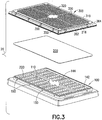
- Filter top assembly 20 can include three parts connected together into one unit: a bonnet 100, a filter 200 and a retainer 300.
- Filter top assembly 20 is preferably in position with respect to cage bottom 10 such that bonnet 100 is in direct contact with cage bottom 10, for example, side walls 14 of cage bottom 10.
- Filter 200 can be positioned above bonnet 100 and retainer 300 can be positioned above filter 200 and preferably secures filter 200 in position between retainer 300 and bonnet 100.
- bonnet 100 is dimensioned and shaped to cover and effectively seal opening 16 of cage bottom 10.
- Bonnet 100 is preferably formed from a resilient material.
- a preferred material includes plastic, which can be relatively light weight and durable. It is to be understood that other materials can also be used without deviating from the scope of the invention.
- Bonnet 100 preferably includes a top wall 110 having a plurality of air passages, such as slots 120, across its surface so that air can pass through top wall 110 of bonnet 100 into and/or out of cage bottom 10.
- Slots 120 are preferably sized and dimensioned to prevent the animal, such as a mouse, rat, and/or other laboratory animal housed in cage 1, from getting a purchase position on bonnet 100 or on filter 200 through slot 120, and further to prevent the animal from accessing the filter material through slot 120. Therefore, the animal can be prevented from reaching filter 200.
- the distance between adjacent slots 120, d1, d2 is greater than the animal can bite or grab with its claws. Therefore, the animal is prevented from getting a purchase position on and biting bonnet 100 and filter 200.
- slots 120 have slanted or rounded walls such that slots 120 have smaller openings on the side facing cage bottom 10 and larger openings facing filter 200.
- Top wall 110 of bonnet 100 can include one or more projections 142, 144 projecting away from cage bottom 10, the projections having a variety of shapes and sizes.
- the projections preferably facilitate maintaining filter 200 suspended away from slots 120 by supporting filter 200 above top wall 110 and thus away from slots 120.
- the projections of bonnet 100 take the form of one or more perimeter ribs 142 and a plurality of internal ribs 144.
- Perimeter ribs 142 can support filter 200 proximate its outer perimeter, and internal ribs 144 can provide support closer to the middle of filter 200. The likelihood that filter 200 can droop toward top wall 110, thus covering one or more slots 120 of bonnet 100, increases as the unsupported surface area of filter 200 increases.
- filter 200 is preferably prevented from drooping and thus from covering slots 120.
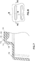
- the internal ribs 144 may also enhance the structural integrity of bonnet 100 and the assembled filter top assembly 20. As shown in greater detail in FIGS. 6-8 , the height of perimeter ribs 142 and internal ribs 144 are substantially equal. Therefore, the distance between filter 200 and top wall 110 of bonnet 100 can be maintained substantially constant.
- a gap 220 can be created and maintained between bonnet 100 and filter 200.
- gap 220 the airflow through filter top assembly 20 can be enhanced.
- the air traveling into gap 220 through slots 120 from cage bottom 10 can disperse within gap 220. The air can then travel through substantially the entire surface area of filter 200.
- Such an arrangement can be beneficial over an arrangement in which filter 200 is flush with top wall 110, wherein air traveling through slot 120 would face an increased pressure differential between cage bottom 10 and filter 100. Also, if filter 200 was flush with top wall 110, air traveling through slot 120 is likely limited to the surface areas of filter 200 exposed by slots 120. By providing gap 220, the air is free to travel through substantially the entire surface area of filter 200, for example, the area within perimeter ribs 142 that do not contact internal ribs 144.
- retainer 300 can be placed on filter 200 and bonnet 100. Filter 200 is thus sandwiched between retainer 300 and bonnet 100.
- Retainer 300 is preferably dimensioned and shaped so as to cover the entire filter 200, thus protecting filter 200 from inadvertent contact. Therefore, once filter top assembly 20 is assembled, filter 200 can be protected from damage from contact by the technician handling filter top assembly 20.
- Retainer 300 can also be perforated, containing apertures 320 throughout its surface 310 to permit air to pass through retainer 300 from gap 220. In accordance with the embodiment shown, apertures 320 can have a generally square shape and form a grid array.
- An exemplary embodiment of retainer 300 of filter top assembly 20 can include the filter retainer described in U.S. Patent No.
- apertures 320 of retainer can be varied without deviating from the scope of the invention.
- apertures 320 can be elongated and have a circular, oval, or polygonal shape without deviating from the scope of the invention.
- retainer 300 is preferably not accessible by the animal.
- bonnet 100 and filter 200 are preferably positioned between cage bottom and retainer 300, thus preventing the animal from getting a purchase position on, biting or chewing retainer 300.
- the width and length of apertures 320 can be larger than that of slots 120, and apertures 320 can be closer together than slots 120 without increasing the risk of damage by the animal.
- bonnet 100 preferably includes one or more projections 146 and retainer 300 preferably includes one or more grooves corresponding to projections 146 of bonnet 100.
- Grooves 346 are preferably shaped, dimensioned and positioned so that when retainer 300 is mounted on bonnet 100, grooves 346 can receive projections 146 of bonnet 100 and secure retainer 300 to bonnet 100.
- filter 200 can be further secured in place between bonnet 100 and retainer 300 via the interaction of grooves 346 and projections 146.
- retainer 300, filter 200 and bonnet 100 can form a unitary structure, namely filter top assembly 20.
- retainer 300 also includes one or more perimeter grooves 342 constructed and arranged to receive perimeter ribs 142 of bonnet 100 when filter top assembly 20 is assembled. Such an arrangement may enhance the pressure on filter 200 between bonnet 100 and retainer 300, which may help maintain filter 200 suspended above top wall 110 of bonnet 100.
- Grooves 346 and/or perimeter grooves 342 can be provided on projections extending from surface 310 toward bonnet 100 such that a gap is provided between filter 200 and surface 310 of retainer 300 as well, which may further enhance airflow through filter 200 and thus in and/or out of cage bottom 10.
- Bonnet 100 and/or retainer 300 are preferably formed of clear plastic which is substantially rigid, but permits a modest degree of flexure when tortional forces are applied thereto. Because the size, shape and arrangement of slots 120 facilitate preventing the animal from biting, chewing or getting a purchase position on bonnet 100, filter top assembly 20 can be provided on cage bottom 10 without a metal shield as described in U.S. Patent No. 6,227,146 assigned to Lab Products, Inc. By providing a plastic filter top assembly 20, the cost of manufacturing filter top assembly 20 can be reduced compared to an embodiment including metal components, such as metal shields at least because metal, which is usually more expensive than plastic, can be eliminated. Furthermore, the step of forming the shield, assembling and mounting the shield onto the bonnet can also be eliminated, which can improve the efficiency of manufacturing filter top assembly 20.
- the weight of filter top assembly 20 can be reduced.
- the reduction in weight can be substantial to a laboratory personnel who often lifts and removes thousands of filter top assemblies from cage bottoms in order to study, process, conduct tests on the animal, or clean the cage, etc.
- the personnel flips the filter top assembly and places it on the work station upside down, such that the retainer is on the bottom. Therefore, the reduction in weight by excluding a metal shield can be a substantial relief for the laboratory personnel.
- Bonnet 100 preferably includes one or more flanges extending downward from top wall 110 constructed and arranged to be spaced from, encompassing and overhanging the lips 18 of side walls 14 of cage bottom 10.
- filter top assembly 20 is preferably prevented from being inadvertently dislodged from cage bottom 10 and must be lifted off to be removed.
- the clearance space between the flange and side walls 14 should permit only a slight movement of bonnet 200 on cage bottom 10.
- bonnet 100 preferably includes a peripheral flange extending laterally sufficiently to remain in contact with the lips 18 of side walls 14 despite relative lateral movement between bonnet 200 and cage bottom 10. Therefore, the integrity of the "petrie dish" configuration between bonnet 200 and cage bottom 10 can be maintained.
- Retainer 300 can be formed of material having the same properties as those of bonnet 100 described above, having the same or different rigidity.
- Retainer 300 can include side walls integrally molded with and extending continuously from top wall 310, and which closely fit the side walls of bonnet 100 as shown in FIG. 3 .
- a lateral peripheral flange 362 preferably extends from the side walls of retainer 300.
- Ribs 364 can extend from respective corners of retainer 300 and enhance structural integrity. Additionally, ribs 364 can act as stacking guides for positioning successive retainers 300.
- filter 200 is a thin sheet of spun-bonded polyester of the type sold by DuPont under the trademark REEMAY 2024.
- a filter thickness of between 11 and 13 mils has been found adequate for a filter having an area approximately equivalent to top wall 110 of bonnet 100.
- REEMAY 2024 is used by way of example only and any filter medium having at least its properties or similar properties may be utilized.
- filter 200 can be placed into retainer 300 or on bonnet 100 such that filter 200 is supported by perimeter ribs 142 and internal ribs 144.
- filter 200 extends beyond all of perimeter ribs 142, thus leaving no area above top wall 110 of bonnet uncovered by filter 200.
- ribs 142, 144 can support filter 200 and maintain filter 200 suspended away from top wall 110.
- filter 200 also covers projections 146 of bonnet 100.
- Retainer 300 can be placed on filter 200 on bonnet 100 or the retainer-filter assembly can be placed on bonnet 100, such that grooves 346 are aligned with corresponding projections 146.
- Retainer 300 or the retainer-filter assembly is preferably pressed onto bonnet 100 such that projections 146 are received by grooves 346, sandwiching filter 200 there between.
- Perimeter grooves 342 may also receive perimeter ribs 142 and portions of filter 200 to sandwich the outer perimeter of filter 200 there between. Accordingly, once retainer 300 engages bonnet 100, for example, via projections 146 and grooves 346 and/or perimeter ribs 142 and perimeter ribs 342, filter 200 can be secured in place and an increased tension can be provided to further facilitate maintaining filter 200 suspended from top wall 110 of bonnet 100.
- Retainer 300 can be further held in place by means of small projections or detents 150 integrally molded on the outer surface of the side walls of bonnet 100.
- apertures or slots 350 can be formed in the side walls of retainer 300 which are positioned and dimensioned so as to snugly receive detents 150 when retainer 300 is mounted on bonnet 100.
- detents may be formed on the inner surface of the side wall of retainer 300, while slots 150 may be formed on the side walls of bonnet 100. It is also possible to dimension retainer 300 to be held to bonnet 100 by another mechanism or a tension fit.
Landscapes
- Life Sciences & Earth Sciences (AREA)
- Zoology (AREA)
- Environmental Sciences (AREA)
- Health & Medical Sciences (AREA)
- Animal Behavior & Ethology (AREA)
- Clinical Laboratory Science (AREA)
- General Health & Medical Sciences (AREA)
- Animal Husbandry (AREA)
- Biodiversity & Conservation Biology (AREA)
- Housing For Livestock And Birds (AREA)
Claims (7)
- Eine Filteroberteilanordnung (20) zur Verwendung mit einem Käfigboden (10), wobei der Käfigboden (10) eine Bodenwand (12) und eine Vielzahl von Seitenwänden (14) hat, die eine Öffnung (16) definieren, und eine Lippe (18) hat, die an der Öffnung (16) angeordnet ist, wobei die Filteroberteilanordnung (20) die Öffnung (16) abdecken kann, wodurch der Käfigboden (10) eingeschlossen wird, wobei die Filteroberteilanordnung (20) umfasst:
eine Haube (100) umfassend:eine obere Wand (110), die eine Vielzahl von Luftpassagen über ihre Oberfläche hat, wobei die Luftpassagen Spalten (120) sind;einen oder mehrere Vorsprünge (142, 144, 146), die an der oberen Wand (110) ausgebildet sind, um einen Filter (200) zu tragen, wobei jeder Vorsprung (142, 144, 146) ausgebildet und angeordnet ist, um den Filter (200) zu tragen und einen im Wesentlichen einheitlichen Filterabstand (220) zwischen dem Filter (200) und den Spalten (120) über der Haube (100) zu definieren;einen oder mehrere Flansche, die sich von der oberen Wand (110) nach unten erstrecken, wobei der eine oder die mehreren Flansche ausgebildet und angeordnet sind, um in die Lippe (18) des Käfigbodens (10) einzugreifen, um den Filterdeckel an dem Käfigboden (10) zu sichern; undeinen oder mehrere sich lateral erstreckende peripheren Flansche, wobei der eine oder die mehreren peripheren Flansche ausgebildet und angeordnet sind, um jede laterale Bewegung zwischen der Haube (100) und dem Käfigboden (10) zu beschränken,dadurch gekennzeichnet, dassdie Spalten (120) geneigte oder abgerundete Wände haben, so dass die Spalten (120) auf der Seite zum Käfigboden (10) hin kleinere Öffnungen und auf der Seite zum Filter (200) hin größere Öffnungen haben. - Die Filteroberteilanordnung (20) nach Anspruch 1, wobei: der eine oder die mehreren Vorsprünge (142, 144, 146) eine Umfangsrippe (142), die entlang einem Haubenumfang der Haube (100) angeordnet ist, und Innenrippen (144) bilden, die selektiv über eine Oberfläche der oberen Wand (110) positioniert sind.
- Die Filteroberteilanordnung (20) nach Anspruch 1 weiter umfassend einen Halter (300), wobei der Halter eine Halteroberfläche (310) und eine oder mehrere Rillen (342, 346), die auf der Halteroberfläche (310) angeordnet sind, umfasst, wobei die eine oder die mehreren Rillen (342, 346) ausgebildet und angeordnet sind, um den einen oder die mehreren Vorsprünge (142, 144, 146) der Haube (100) derart zu spiegeln, dass die eine oder die mehreren Rillen (342, 346) den einen oder die mehreren Vorsprünge (142, 144, 146) aufnehmen können, um den Halter (300) an der Haube (100) zu sichern und um zudem den Filter (200) zwischen der Haube (100) und dem Halter (300) zu halten, wobei der Halter (300) selektiv mit der Haube (100) oder dem Filter (200) in Eingriff bringbar ist und selektiv oberhalb des Filters (200) positionierbar ist.
- Die Filteroberteilanordnung (20) nach Anspruch 3 wobei: die Halteroberfläche (310) eine oder mehrere Halteröffnungen (320) definiert.
- Die Filteroberteilanordnung (20) nach Anspruch 4, wobei: die Halteröffnungen (320) ausgebildet und angeordnet sind, um ein Gitteranordnung zu bilden.
- Die Filteroberteilanordnung (20) nach Anspruch 3, wobei: der Halter (300) einen oder mehrere Haltervorsprünge umfasst, die sich auf die Haube (100) zu erstrecken, wobei der eine oder die mehreren Haltervorsprünge einen Halterabstand zwischen dem Halter (300) und dem Filter (200) definieren.
- Die Filteroberteilanordnung (20) nach Anspruch 3, wobei die eine oder die mehreren Rillen (342, 346) auf Vorsprüngen vorgesehen sind, die sich von der Halteroberfläche (310) auf die Haube (100) zu erstrecken, sodass ein Abstand zwischen dem Filter (200) und der Halteroberfläche (310) ausgebildet ist, um einen Luftstrom durch den Filter (200) zu verbessern und somit in und/oder aus dem Käfigboden (10).
Applications Claiming Priority (2)
| Application Number | Priority Date | Filing Date | Title |
|---|---|---|---|
| US9078308P | 2008-08-21 | 2008-08-21 | |
| PCT/US2009/004780 WO2010021742A1 (en) | 2008-08-21 | 2009-08-21 | Filter top assembly |
Publications (2)
| Publication Number | Publication Date |
|---|---|
| EP2317836A1 EP2317836A1 (de) | 2011-05-11 |
| EP2317836B1 true EP2317836B1 (de) | 2021-04-28 |
Family
ID=41466995
Family Applications (1)
| Application Number | Title | Priority Date | Filing Date |
|---|---|---|---|
| EP09789185.7A Active EP2317836B1 (de) | 2008-08-21 | 2009-08-21 | Filterdeckelanordnung |
Country Status (9)
| Country | Link |
|---|---|
| US (1) | US8151733B2 (de) |
| EP (1) | EP2317836B1 (de) |
| JP (1) | JP5523460B2 (de) |
| CN (1) | CN102202499A (de) |
| AU (1) | AU2009283147B2 (de) |
| CA (1) | CA2734743C (de) |
| IL (1) | IL211285A (de) |
| MX (1) | MX2011001971A (de) |
| WO (1) | WO2010021742A1 (de) |
Families Citing this family (7)
| Publication number | Priority date | Publication date | Assignee | Title |
|---|---|---|---|---|
| CN102499100A (zh) * | 2011-09-30 | 2012-06-20 | 府志红 | 垂直流ivc笼盒 |
| USD699407S1 (en) * | 2013-03-12 | 2014-02-11 | Target Brands, Inc. | Litter box |
| USD752297S1 (en) * | 2014-01-17 | 2016-03-22 | Kabushiki Kaisha Tominaga Jyushi Kogyosho | Container for breeding small animals |
| JP1519051S (de) * | 2014-07-03 | 2015-03-09 | ||
| US12201082B2 (en) * | 2018-01-17 | 2025-01-21 | Case Western Reserve University | Multilayer, static housing systems |
| USD899714S1 (en) * | 2019-02-07 | 2020-10-20 | Patricia McBrien | Enclosed litter box |
| CN111264403A (zh) * | 2020-01-18 | 2020-06-12 | 苏州建发塑料制品有限公司 | 一种实验室用封闭式全膜大鼠用鼠笼 |
Citations (1)
| Publication number | Priority date | Publication date | Assignee | Title |
|---|---|---|---|---|
| US3334614A (en) * | 1966-04-06 | 1967-08-08 | Univ Southern Illinois | Animal cage feeding lid |
Family Cites Families (16)
| Publication number | Priority date | Publication date | Assignee | Title |
|---|---|---|---|---|
| US3212474A (en) * | 1963-07-09 | 1965-10-19 | Roehr Products Company Inc | Animal housing structure |
| JPS5762559U (de) * | 1980-10-01 | 1982-04-14 | ||
| US4480587A (en) * | 1982-09-23 | 1984-11-06 | Lab Products, Inc. | Animal cage assembly with reusable filter cap |
| US4907536A (en) * | 1987-03-03 | 1990-03-13 | Chrisler Tanner S | Isolating container for live animals |
| US5924384A (en) * | 1995-10-12 | 1999-07-20 | Lab Products, Inc. | Animal cage assembly and combination water bottle holder and feeder |
| US20020069834A1 (en) * | 1995-10-12 | 2002-06-13 | Deitrich Eric A. | Cage assembly |
| US5954013A (en) * | 1996-09-18 | 1999-09-21 | Lab Products Inc. | Ventilated cage and rack system |
| US6041741A (en) * | 1998-06-26 | 2000-03-28 | Lab Products, Inc. | Multispecies rodent cage |
| US6257171B1 (en) * | 1998-01-16 | 2001-07-10 | Animal Care Systems, Inc. | Animal caging and biological storage systems |
| US6227146B1 (en) * | 1998-06-26 | 2001-05-08 | Lab Products Inc. | Filter top for rodent cage |
| EP1191838B1 (de) | 1999-06-07 | 2004-09-08 | Lab Products Inc. | Filterdeckelanordnung für nagetierkäfig |
| US6543387B1 (en) * | 2002-01-15 | 2003-04-08 | Miro Mold Tools Corp. | Shipping container for rodents |
| US7320294B2 (en) * | 2002-10-25 | 2008-01-22 | Lab Products, Inc. | Cage and rack system for housing animals in cages having different widths |
| US7595032B2 (en) * | 2004-03-08 | 2009-09-29 | Banks Percival C | Protected seal for a filtered vent in a sterilization container |
| US7661392B2 (en) * | 2004-12-13 | 2010-02-16 | Innovive, Inc. | Containment systems and components for animal husbandry: nested cage bases |
| NZ542641A (en) * | 2005-09-27 | 2008-06-30 | Fmfs Holdings Ltd | Toileting device for a domestic animal |
-
2009
- 2009-08-21 EP EP09789185.7A patent/EP2317836B1/de active Active
- 2009-08-21 AU AU2009283147A patent/AU2009283147B2/en not_active Ceased
- 2009-08-21 MX MX2011001971A patent/MX2011001971A/es active IP Right Grant
- 2009-08-21 CA CA2734743A patent/CA2734743C/en not_active Expired - Fee Related
- 2009-08-21 US US12/583,517 patent/US8151733B2/en active Active
- 2009-08-21 JP JP2011523822A patent/JP5523460B2/ja active Active
- 2009-08-21 CN CN2009801418479A patent/CN102202499A/zh active Pending
- 2009-08-21 WO PCT/US2009/004780 patent/WO2010021742A1/en not_active Ceased
-
2011
- 2011-02-17 IL IL211285A patent/IL211285A/en active IP Right Grant
Patent Citations (1)
| Publication number | Priority date | Publication date | Assignee | Title |
|---|---|---|---|---|
| US3334614A (en) * | 1966-04-06 | 1967-08-08 | Univ Southern Illinois | Animal cage feeding lid |
Also Published As
| Publication number | Publication date |
|---|---|
| CA2734743A1 (en) | 2010-02-25 |
| AU2009283147B2 (en) | 2014-10-23 |
| IL211285A0 (en) | 2011-04-28 |
| AU2009283147A1 (en) | 2010-02-25 |
| JP5523460B2 (ja) | 2014-06-18 |
| US20100132623A1 (en) | 2010-06-03 |
| CA2734743C (en) | 2016-12-06 |
| JP2012500022A (ja) | 2012-01-05 |
| CN102202499A (zh) | 2011-09-28 |
| EP2317836A1 (de) | 2011-05-11 |
| IL211285A (en) | 2013-11-28 |
| WO2010021742A1 (en) | 2010-02-25 |
| US8151733B2 (en) | 2012-04-10 |
| MX2011001971A (es) | 2011-08-08 |
Similar Documents
| Publication | Publication Date | Title |
|---|---|---|
| EP2317836B1 (de) | Filterdeckelanordnung | |
| US6729266B1 (en) | Animal isolation and caging system | |
| US6158387A (en) | Ventilated cage and rack system | |
| US6227146B1 (en) | Filter top for rodent cage | |
| US7320294B2 (en) | Cage and rack system for housing animals in cages having different widths | |
| CA2625589C (en) | Multispecies rodent cage | |
| JP5992459B2 (ja) | 齧歯類動物用のフィルタ・トップ | |
| WO2003009676A9 (en) | Animal cage assembly and combination water bottle holder and feeder | |
| JP4578845B2 (ja) | 培養皿アセンブリ | |
| GB2342840A (en) | A lock for a rodent cage, including a visual alert | |
| GB2386816A (en) | Animal Cage Feeder Assembly | |
| AU5653400A (en) | A filter cap | |
| AU5323600A (en) | Filter top for rodent cage |
Legal Events
| Date | Code | Title | Description |
|---|---|---|---|
| PUAI | Public reference made under article 153(3) epc to a published international application that has entered the european phase |
Free format text: ORIGINAL CODE: 0009012 |
|
| 17P | Request for examination filed |
Effective date: 20110221 |
|
| AK | Designated contracting states |
Kind code of ref document: A1 Designated state(s): AT BE BG CH CY CZ DE DK EE ES FI FR GB GR HR HU IE IS IT LI LT LU LV MC MK MT NL NO PL PT RO SE SI SK SM TR |
|
| AX | Request for extension of the european patent |
Extension state: AL BA RS |
|
| DAX | Request for extension of the european patent (deleted) | ||
| STAA | Information on the status of an ep patent application or granted ep patent |
Free format text: STATUS: EXAMINATION IS IN PROGRESS |
|
| 17Q | First examination report despatched |
Effective date: 20170202 |
|
| RIN1 | Information on inventor provided before grant (corrected) |
Inventor name: IRWIN, LYNN Inventor name: CAMPBELL, NEIL, E. Inventor name: GERRINGER, RODNEY Inventor name: MURRAY, DALE Inventor name: MILLER, CURTIS Inventor name: PARK, CHINSOO Inventor name: GABRIEL, GEORGE, S. |
|
| RIN1 | Information on inventor provided before grant (corrected) |
Inventor name: CAMPBELL, NEIL E. Inventor name: PARK, CHINSOO Inventor name: MILLER, CURTIS Inventor name: GABRIEL, GEORGE S. Inventor name: GERRINGER, RODNEY Inventor name: MURRAY, DALE Inventor name: IRWIN, LYNN |
|
| GRAP | Despatch of communication of intention to grant a patent |
Free format text: ORIGINAL CODE: EPIDOSNIGR1 |
|
| STAA | Information on the status of an ep patent application or granted ep patent |
Free format text: STATUS: GRANT OF PATENT IS INTENDED |
|
| INTG | Intention to grant announced |
Effective date: 20201113 |
|
| GRAS | Grant fee paid |
Free format text: ORIGINAL CODE: EPIDOSNIGR3 |
|
| GRAA | (expected) grant |
Free format text: ORIGINAL CODE: 0009210 |
|
| STAA | Information on the status of an ep patent application or granted ep patent |
Free format text: STATUS: THE PATENT HAS BEEN GRANTED |
|
| RAP1 | Party data changed (applicant data changed or rights of an application transferred) |
Owner name: LAB PRODUCTS, LLC |
|
| AK | Designated contracting states |
Kind code of ref document: B1 Designated state(s): AT BE BG CH CY CZ DE DK EE ES FI FR GB GR HR HU IE IS IT LI LT LU LV MC MK MT NL NO PL PT RO SE SI SK SM TR |
|
| RAP3 | Party data changed (applicant data changed or rights of an application transferred) |
Owner name: LAB PRODUCTS, LLC |
|
| REG | Reference to a national code |
Ref country code: GB Ref legal event code: FG4D |
|
| REG | Reference to a national code |
Ref country code: CH Ref legal event code: EP |
|
| REG | Reference to a national code |
Ref country code: DE Ref legal event code: R096 Ref document number: 602009063644 Country of ref document: DE |
|
| REG | Reference to a national code |
Ref country code: AT Ref legal event code: REF Ref document number: 1386053 Country of ref document: AT Kind code of ref document: T Effective date: 20210515 |
|
| REG | Reference to a national code |
Ref country code: IE Ref legal event code: FG4D |
|
| REG | Reference to a national code |
Ref country code: NL Ref legal event code: FP |
|
| REG | Reference to a national code |
Ref country code: SE Ref legal event code: TRGR |
|
| REG | Reference to a national code |
Ref country code: LT Ref legal event code: MG9D |
|
| REG | Reference to a national code |
Ref country code: AT Ref legal event code: MK05 Ref document number: 1386053 Country of ref document: AT Kind code of ref document: T Effective date: 20210428 |
|
| PG25 | Lapsed in a contracting state [announced via postgrant information from national office to epo] |
Ref country code: FI Free format text: LAPSE BECAUSE OF FAILURE TO SUBMIT A TRANSLATION OF THE DESCRIPTION OR TO PAY THE FEE WITHIN THE PRESCRIBED TIME-LIMIT Effective date: 20210428 Ref country code: LT Free format text: LAPSE BECAUSE OF FAILURE TO SUBMIT A TRANSLATION OF THE DESCRIPTION OR TO PAY THE FEE WITHIN THE PRESCRIBED TIME-LIMIT Effective date: 20210428 Ref country code: BG Free format text: LAPSE BECAUSE OF FAILURE TO SUBMIT A TRANSLATION OF THE DESCRIPTION OR TO PAY THE FEE WITHIN THE PRESCRIBED TIME-LIMIT Effective date: 20210728 Ref country code: AT Free format text: LAPSE BECAUSE OF FAILURE TO SUBMIT A TRANSLATION OF THE DESCRIPTION OR TO PAY THE FEE WITHIN THE PRESCRIBED TIME-LIMIT Effective date: 20210428 Ref country code: HR Free format text: LAPSE BECAUSE OF FAILURE TO SUBMIT A TRANSLATION OF THE DESCRIPTION OR TO PAY THE FEE WITHIN THE PRESCRIBED TIME-LIMIT Effective date: 20210428 |
|
| PGFP | Annual fee paid to national office [announced via postgrant information from national office to epo] |
Ref country code: IT Payment date: 20210831 Year of fee payment: 13 |
|
| PG25 | Lapsed in a contracting state [announced via postgrant information from national office to epo] |
Ref country code: NO Free format text: LAPSE BECAUSE OF FAILURE TO SUBMIT A TRANSLATION OF THE DESCRIPTION OR TO PAY THE FEE WITHIN THE PRESCRIBED TIME-LIMIT Effective date: 20210728 Ref country code: PL Free format text: LAPSE BECAUSE OF FAILURE TO SUBMIT A TRANSLATION OF THE DESCRIPTION OR TO PAY THE FEE WITHIN THE PRESCRIBED TIME-LIMIT Effective date: 20210428 Ref country code: PT Free format text: LAPSE BECAUSE OF FAILURE TO SUBMIT A TRANSLATION OF THE DESCRIPTION OR TO PAY THE FEE WITHIN THE PRESCRIBED TIME-LIMIT Effective date: 20210830 Ref country code: ES Free format text: LAPSE BECAUSE OF FAILURE TO SUBMIT A TRANSLATION OF THE DESCRIPTION OR TO PAY THE FEE WITHIN THE PRESCRIBED TIME-LIMIT Effective date: 20210428 Ref country code: LV Free format text: LAPSE BECAUSE OF FAILURE TO SUBMIT A TRANSLATION OF THE DESCRIPTION OR TO PAY THE FEE WITHIN THE PRESCRIBED TIME-LIMIT Effective date: 20210428 Ref country code: GR Free format text: LAPSE BECAUSE OF FAILURE TO SUBMIT A TRANSLATION OF THE DESCRIPTION OR TO PAY THE FEE WITHIN THE PRESCRIBED TIME-LIMIT Effective date: 20210729 Ref country code: IS Free format text: LAPSE BECAUSE OF FAILURE TO SUBMIT A TRANSLATION OF THE DESCRIPTION OR TO PAY THE FEE WITHIN THE PRESCRIBED TIME-LIMIT Effective date: 20210828 |
|
| PGFP | Annual fee paid to national office [announced via postgrant information from national office to epo] |
Ref country code: GB Payment date: 20210823 Year of fee payment: 13 Ref country code: DE Payment date: 20210826 Year of fee payment: 13 |
|
| PG25 | Lapsed in a contracting state [announced via postgrant information from national office to epo] |
Ref country code: RO Free format text: LAPSE BECAUSE OF FAILURE TO SUBMIT A TRANSLATION OF THE DESCRIPTION OR TO PAY THE FEE WITHIN THE PRESCRIBED TIME-LIMIT Effective date: 20210428 Ref country code: EE Free format text: LAPSE BECAUSE OF FAILURE TO SUBMIT A TRANSLATION OF THE DESCRIPTION OR TO PAY THE FEE WITHIN THE PRESCRIBED TIME-LIMIT Effective date: 20210428 Ref country code: CZ Free format text: LAPSE BECAUSE OF FAILURE TO SUBMIT A TRANSLATION OF THE DESCRIPTION OR TO PAY THE FEE WITHIN THE PRESCRIBED TIME-LIMIT Effective date: 20210428 Ref country code: DK Free format text: LAPSE BECAUSE OF FAILURE TO SUBMIT A TRANSLATION OF THE DESCRIPTION OR TO PAY THE FEE WITHIN THE PRESCRIBED TIME-LIMIT Effective date: 20210428 Ref country code: SK Free format text: LAPSE BECAUSE OF FAILURE TO SUBMIT A TRANSLATION OF THE DESCRIPTION OR TO PAY THE FEE WITHIN THE PRESCRIBED TIME-LIMIT Effective date: 20210428 Ref country code: SM Free format text: LAPSE BECAUSE OF FAILURE TO SUBMIT A TRANSLATION OF THE DESCRIPTION OR TO PAY THE FEE WITHIN THE PRESCRIBED TIME-LIMIT Effective date: 20210428 |
|
| REG | Reference to a national code |
Ref country code: DE Ref legal event code: R097 Ref document number: 602009063644 Country of ref document: DE |
|
| PLBE | No opposition filed within time limit |
Free format text: ORIGINAL CODE: 0009261 |
|
| STAA | Information on the status of an ep patent application or granted ep patent |
Free format text: STATUS: NO OPPOSITION FILED WITHIN TIME LIMIT |
|
| REG | Reference to a national code |
Ref country code: SE Ref legal event code: EUG |
|
| REG | Reference to a national code |
Ref country code: CH Ref legal event code: PL |
|
| PG25 | Lapsed in a contracting state [announced via postgrant information from national office to epo] |
Ref country code: MC Free format text: LAPSE BECAUSE OF FAILURE TO SUBMIT A TRANSLATION OF THE DESCRIPTION OR TO PAY THE FEE WITHIN THE PRESCRIBED TIME-LIMIT Effective date: 20210428 |
|
| 26N | No opposition filed |
Effective date: 20220131 |
|
| REG | Reference to a national code |
Ref country code: NL Ref legal event code: MM Effective date: 20210901 |
|
| REG | Reference to a national code |
Ref country code: BE Ref legal event code: MM Effective date: 20210831 |
|
| PG25 | Lapsed in a contracting state [announced via postgrant information from national office to epo] |
Ref country code: LI Free format text: LAPSE BECAUSE OF NON-PAYMENT OF DUE FEES Effective date: 20210831 Ref country code: CH Free format text: LAPSE BECAUSE OF NON-PAYMENT OF DUE FEES Effective date: 20210831 |
|
| PG25 | Lapsed in a contracting state [announced via postgrant information from national office to epo] |
Ref country code: IS Free format text: LAPSE BECAUSE OF FAILURE TO SUBMIT A TRANSLATION OF THE DESCRIPTION OR TO PAY THE FEE WITHIN THE PRESCRIBED TIME-LIMIT Effective date: 20210828 Ref country code: SE Free format text: LAPSE BECAUSE OF NON-PAYMENT OF DUE FEES Effective date: 20210822 Ref country code: LU Free format text: LAPSE BECAUSE OF NON-PAYMENT OF DUE FEES Effective date: 20210821 |
|
| PG25 | Lapsed in a contracting state [announced via postgrant information from national office to epo] |
Ref country code: NL Free format text: LAPSE BECAUSE OF NON-PAYMENT OF DUE FEES Effective date: 20210901 |
|
| PG25 | Lapsed in a contracting state [announced via postgrant information from national office to epo] |
Ref country code: IE Free format text: LAPSE BECAUSE OF NON-PAYMENT OF DUE FEES Effective date: 20210821 Ref country code: FR Free format text: LAPSE BECAUSE OF NON-PAYMENT OF DUE FEES Effective date: 20210831 Ref country code: BE Free format text: LAPSE BECAUSE OF NON-PAYMENT OF DUE FEES Effective date: 20210831 |
|
| REG | Reference to a national code |
Ref country code: DE Ref legal event code: R119 Ref document number: 602009063644 Country of ref document: DE |
|
| GBPC | Gb: european patent ceased through non-payment of renewal fee |
Effective date: 20220821 |
|
| PG25 | Lapsed in a contracting state [announced via postgrant information from national office to epo] |
Ref country code: HU Free format text: LAPSE BECAUSE OF FAILURE TO SUBMIT A TRANSLATION OF THE DESCRIPTION OR TO PAY THE FEE WITHIN THE PRESCRIBED TIME-LIMIT; INVALID AB INITIO Effective date: 20090821 Ref country code: CY Free format text: LAPSE BECAUSE OF FAILURE TO SUBMIT A TRANSLATION OF THE DESCRIPTION OR TO PAY THE FEE WITHIN THE PRESCRIBED TIME-LIMIT Effective date: 20210428 |
|
| PG25 | Lapsed in a contracting state [announced via postgrant information from national office to epo] |
Ref country code: IT Free format text: LAPSE BECAUSE OF NON-PAYMENT OF DUE FEES Effective date: 20220821 Ref country code: DE Free format text: LAPSE BECAUSE OF NON-PAYMENT OF DUE FEES Effective date: 20230301 |
|
| PG25 | Lapsed in a contracting state [announced via postgrant information from national office to epo] |
Ref country code: GB Free format text: LAPSE BECAUSE OF NON-PAYMENT OF DUE FEES Effective date: 20220821 |
|
| PG25 | Lapsed in a contracting state [announced via postgrant information from national office to epo] |
Ref country code: MK Free format text: LAPSE BECAUSE OF FAILURE TO SUBMIT A TRANSLATION OF THE DESCRIPTION OR TO PAY THE FEE WITHIN THE PRESCRIBED TIME-LIMIT Effective date: 20210428 |
|
| PG25 | Lapsed in a contracting state [announced via postgrant information from national office to epo] |
Ref country code: TR Free format text: LAPSE BECAUSE OF FAILURE TO SUBMIT A TRANSLATION OF THE DESCRIPTION OR TO PAY THE FEE WITHIN THE PRESCRIBED TIME-LIMIT Effective date: 20210428 |
|
| PG25 | Lapsed in a contracting state [announced via postgrant information from national office to epo] |
Ref country code: MT Free format text: LAPSE BECAUSE OF FAILURE TO SUBMIT A TRANSLATION OF THE DESCRIPTION OR TO PAY THE FEE WITHIN THE PRESCRIBED TIME-LIMIT Effective date: 20210428 |