EP2317843B1 - Schlagfalle - Google Patents
Schlagfalle Download PDFInfo
- Publication number
- EP2317843B1 EP2317843B1 EP08787553.0A EP08787553A EP2317843B1 EP 2317843 B1 EP2317843 B1 EP 2317843B1 EP 08787553 A EP08787553 A EP 08787553A EP 2317843 B1 EP2317843 B1 EP 2317843B1
- Authority
- EP
- European Patent Office
- Prior art keywords
- snap trap
- base plate
- triggering part
- trap
- locking lever
- Prior art date
- Legal status (The legal status is an assumption and is not a legal conclusion. Google has not performed a legal analysis and makes no representation as to the accuracy of the status listed.)
- Not-in-force
Links
Images

Classifications
-
- A—HUMAN NECESSITIES
- A01—AGRICULTURE; FORESTRY; ANIMAL HUSBANDRY; HUNTING; TRAPPING; FISHING
- A01M—CATCHING, TRAPPING OR SCARING OF ANIMALS; APPARATUS FOR THE DESTRUCTION OF NOXIOUS ANIMALS OR NOXIOUS PLANTS
- A01M23/00—Traps for animals
- A01M23/24—Spring traps, e.g. jaw or like spring traps
- A01M23/30—Break-back traps, i.e. mouse-trap type
Definitions
- the invention relates to a trap for mice, rats or other small animals according to the preamble of claim 1.
- Drop traps have been known and used for some time. Generically comparable drop traps are for example from the DE 20 348 45 or the DE 821 877 known.
- the impact trap consists of a base plate, a beater bar, a pivotable tongue as a trigger part and a locking lever for fixing the bracket in a standby position.
- the bracket is pivotally mounted on the base plate and can be prestressed in a standby position against the spring force of a leg spring.
- the tongue is - like the base plate - made of wood.
- the tongue is equipped with a headband of wire, in which for tensioning the case, the front, free end of the locking lever can be introduced.
- the movable tongue Since the movable tongue is firmly connected via an axis to the base plate, it can not be removed, for example, to clean the bait holder.
- the trigger assembly consists of two parts (ie tongue, headband), whereby the case is constructed relatively complicated. Then the tensioning of the trap requires a certain skill and false triggering when setting the trap can occur frequently in practice.
- the trigger part should be simple and inexpensive to produce.
- the trigger assembly should be easy to disassemble and allow easy cleaning.
- the trap contains a mounted on the base plate swivel bracket.
- the bracket can be in the impact position in a front area and in the standby position in a rear area of the base plate.
- the pivoting range given by the ready position on the one hand and the impact position on the other hand, can be about 180 °.
- To tighten the case of the bracket from the impact position (or rest position) is pivoted about 180 ° and fixed in the pivoted position by means of the locking lever.
- the locking lever is releasably connected to the trigger part.
- the connection between the locking lever and the trigger part can be canceled, whereby the mouse is killed by the swinging back strap.
- the triggering part is formed as a one-piece molded body, there are several advantages. On the one hand, such a shaped body is simple and inexpensive to produce.
- the bait receptacle and the means for fixing the standby position cooperating with the blocking lever can be formed on the triggering part and preferably consist of the same material.
- the release part is mounted like a rocker on the base plate.
- This rocker-like release part may consist of a first and a second rocker segment, wherein between the first and second rocker segment an edge is arranged around which the trigger part is rocker-like movable.
- Such a rocker in addition to a reliable triggering further has the advantage that the handling of the trap can be simplified when placing.
- the trigger part has a touch-sensitive, first rocker segment, which is surrounded in the impact position relative to a plan view of the bracket.
- the plan view is preferably predetermined by a viewing direction which runs parallel to the surface normal of an upper side of the base plate.
- the triggering part has a touch-sensitive, first rocker segment and if the hoop can be guided past the first rocker segment during the transition from the ready position into the striking position.
- an abutment can be arranged for storage of the release part on an upper side of the base plate.
- the simple attachment of the abutment on the base plate manufacturing costs can be further reduced.
- the abutment can consist of wire.
- the abutment is U-shaped.
- the U-shaped abutment may have approximately parallel arms which penetrate into a preferably wooden base plate. Such an abutment can be introduced, for example by a hammer blow in a wooden plate.
- the U-shaped abutment may further have an approximately rectangular configuration, wherein it may include two arms and a web connecting them.
- the trigger member may be releasably attached or attachable to the base plate.
- This embodiment allows a particularly simple mounting and dismounting of the trigger part associated bait receptacle. It may be particularly advantageous when the trigger member is locked or latched to the abutment.
- Such a snap or latching connection has a positive effect on the handling of the case.
- the locking connection may be predetermined for example by the web of the U-shaped abutment on one side and by the latching part molded latching parts on the other side.
- the trigger member has an engaging portion against which a free end of the locking lever for setting the standby position can be supported.
- the attacking section is provided with an undercut.
- the undercut allows a relatively secure provisional connection between the locking lever and trigger part in the ready position. Another advantage of this arrangement is that the ready position can be reached easily and with little effort, since the two components of the release mechanism corresponding to one another can be connected to one another in a latching manner. Such an embodiment of the triggering mechanism can of course also be advantageous in combination with conventional mousetraps.
- the Auletteteil has a recess into which the locking lever is inserted.
- the introduced into the recess part of the locking lever is thus not free. He is in a sense "hidden", whereby the risk of accidents can be significantly reduced.
- the recess extends in a predetermined by the locking lever longitudinal direction to one end, wherein at this end of the engaging portion is arranged for the locking lever.
- the depression is channel-like. The depression can be arranged in the second rocker segment of the release part.
- the spring element may be a leg spring with a helical portion. It may be advantageous if the second rocker segment has a recess into which the helical portion is receivable. This recess can be formed such that the second (or rear) rocker segment engages over the helical portion in any position, whereby the rocker-like tilting movement of the trigger member is not disturbed.
- the release part is made of plastic.
- the base plate made of wood or plastic.
- the trigger part is an injection molded part made of plastic.
- the base plate may consist of a single wooden component. By eliminating other components made of wood, the assembly of the impact trap can be simplified.
- the wooden component can be easily cut out of a wooden board and does not need to be further processed on a larger scale. In particular, no further drilling or milling operations are necessary.
- the efficiency of the trap can be further increased if the bracket and / or a stroke of the bracket associated front portion of the base plate and optionally associated with a bait receiving portion of the trigger member (for example, the first rocker segment) in a plan view arcuate, and preferably approximately semicircular ,
- the bow shape has the advantage that small animals can be relatively reliably detected not only centrally from the front, but also with a more or less lateral approach.
- the arcuate shape of the base plate can also bring advantages without the use of the one-piece shaped body release part described above for species-comparable animal traps.
- FIG. 1 shows a designated with 1 trap, with the mice in particular can be caught in an advantageous manner.
- the trap is also suitable for catching rats or other small animals. As with the well-known classic falling traps, these small animals are killed when striking a stirrup.
- the essential components of the trap 1 are: a base plate 2, a bracket 3, a spring element 5, a trigger part 4 and a locking lever 6.
- the trigger part 4 is made of plastic
- the base plate 2 is made of wood
- the other components are each made of wire.
- the trigger part 4 is preferably an injection molded part made of plastic.
- This one-piece molded body forms a kind of rocker with a first (or front) rocker segment 7 and a second (or rear) rocker segment 8.
- the rear rocker segment 8 is in the standby position on the base plate 2, while the front rocker segment 7 protrudes slightly from the top of the base plate.
- a touch-sensitive segment 8 is created, which tilts the front segment 7 down when touched by an approaching mouse.
- the lure segment 11 associated bait receiving 11 includes a plurality of knob-like elevations for attaching bait.
- FIG. 1 is a channel-like recess 9 can be seen, which extends in the longitudinal direction to the front rocker segment 7 facing the end. This end forms an engaging portion which is provided with an undercut 13.
- the free end 12 of the locking lever 6 is supported in the ready position on the engaging portion 10 (see. Fig. 2 ).
- the undercut 13 prevents unintentional triggering of the catch. Due to the inventive use of the rocker-like release part 4 and the undercut 13, the ready position can be created easily and with little effort.
- the locking lever 6 has a free end 12, which can be supported for setting the ready position on the engagement portion of the release part 4.
- the engagement portion is arranged at the rear end of a channel-like recess 9, which extends in a predetermined by the locking lever 6 longitudinal direction up to this end (see. Fig. 2 ).
- a channel-like recess 9 which extends in a predetermined by the locking lever 6 longitudinal direction up to this end (see. Fig. 2 ).
- FIG. 1 shows further that the touch-sensitive first rocker segment 7 is surrounded in the impact position with respect to a plan view of the bracket 3.
- the bracket 3 is at the transition from the ready position ( Fig. 2 ) in the striking position ( Fig. 1 ) can be moved past the first rocker segment 7.
- the second rocker segment 8 has a recess 16, in which a helical portion 15 of the spring element 5 can be accommodated.
- the bracket 3 and the impact position of the bracket associated front portion 17 of the base plate 2 and the bait receiving associated region 7 of the trigger member 4 are arcuate in plan view, in particular approximately semicircular.
- FIG. 2 shows, it is the spring element 5 - as in the classic falling traps - a leg spring (but see also below Fig. 5 ).
- the leg spring has a helical portion 15 which is received in a recess 16 of the trigger part 4.
- the bracket 3 is connected to the spring element 5 such that it is biased in the standby position against the spring force of the spring element.
- the locking lever 6 is hinged at the rear end of the base plate 2 on the case - analogous to classic impact traps.
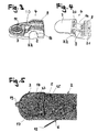
- FIGS. 3 and 4 show the trigger part in a front and a rear view.
- the trigger part 4 is locked or latched to the abutment 14.
- FIG. 4 shows molded on the trigger part Latching members 20 which cooperate to create a latching connection with a web of a U-shaped abutment (see. Fig. 5 ).
- the bracket in the plan view is approximately semicircular, with a centrally opposite to the semicircle projecting U-section 19 is integrally formed on the bracket 3.
- the U-section 19 protrudes in the rest position, which corresponds to the impact position, over the arcuate front portion of the base plate 2, whereby the bracket 2 can be easily detected and folded or clamped.
- the base plate 2 is obviously made of a single wood component.
- an abutment 14 can be seen, which serves for the storage of the release part.
- the abutment 14 is made of wire and is arranged on the upper side of the base plate 2.
- the abutment 14 is U-shaped and has approximately parallel arms (not visible here) and a web connecting them 23, which penetrate into the base plate 2 made of wood.
- the web 23 serves as a counterpart for the latching pawl parts of the release part.
Landscapes
- Life Sciences & Earth Sciences (AREA)
- Pest Control & Pesticides (AREA)
- Engineering & Computer Science (AREA)
- Insects & Arthropods (AREA)
- Wood Science & Technology (AREA)
- Zoology (AREA)
- Environmental Sciences (AREA)
- Catching Or Destruction (AREA)
Description
- Die Erfindung betrifft eine Schlagfalle für Mäuse, Ratten oder andere Kleintiere gemäss dem Oberbegriff von Anspruch 1.
- Schlagfallen sind seit längerer Zeit bekannt und gebräuchlich. Gattungsmässig vergleichbare Schlagfallen sind beispielsweise aus der
DE 20 348 45 oder derDE 821 877 bekannt geworden. Die Schlagfalle besteht aus einer Grundplatte, einem Schlagbügel, einer schwenkbaren Zunge als Auslöseteil und einem Sperrhebel zum Fixieren des Bügels in einer Bereitschaftsstellung. Der Bügel ist auf der Grundplatte schwenkbar gelagert und in einer Bereitschaftsstellung gegen die Federkraft einer Schenkelfeder vorspannbar. Die Zunge besteht - wie die Grundplatte - aus Holz. Die Zunge ist mit einem Haltebügel aus Draht bestückt, in welchen zum Spannen der Falle das vordere, freie Ende des Sperrhebels einbringbar ist. Da die bewegliche Zunge fest über eine Achse mit der Grundplatte verbunden ist, kann sie beispielsweise zum Reinigen der Köderaufnahme nicht entfernt werden. Ein weiterer Nachteil besteht darin, dass die Auslöseanordnung aus zwei Einzelteilen (d.h. Zunge, Haltebügel) besteht, wodurch die Falle verhältnismässig kompliziert aufgebaut ist. Sodann erfordert das Spannen der Falle ein gewisses Geschick und Fehlauslösungen beim Stellen der Falle können in der Praxis häufig vorkommen. - Es ist deshalb eine Aufgabe der vorliegenden Erfindung, die Nachteile des Bekannten zu vermeiden und insbesondere eine Schlagfalle zu schaffen, die sich durch eine optimierte Auslöseanordnung auszeichnet. Das Auslöseteil soll einfach und kostengünstig herstellbar sein. Die Auslöseanordnung soll einfach demontierbar sein und so eine einfache Reinigung ermöglichen.
- Das Dokument
US-A-1501384 offenbart eine Schlagfalle gemäß dem Oberbegriff des unabhängigen Anspruchs 1. - Diese Aufgaben werden mit einer Schlagfalle gelöst, die die Merkmale des Anspruchs 1 aufweist.
- Die Schlagfalle enthält einen auf der Grundplatte gelagerten schwenkbaren Bügel. Der Bügel kann sich in der Schlagstellung in einem vorderen Bereich und in der Bereitschaftsstellung in einem hinteren Bereich der Grundplatte befinden. Der Schwenkbereich, vorgegeben durch die Bereitschaftsstellung einerseits und durch die Schlagstellung andererseits, kann etwa 180° betragen. Zum Spannen der Falle wird der Bügel aus der Schlagstellung (bzw. Ruhestellung) etwa um 180° geschwenkt und in der ausgeschwenkten Stellung mittels des Sperrhebels fixiert. In dieser Bereitschaftsstellung ist der Sperrhebel lösbar mit dem Auslöseteil verbunden. Bei einer Berührung des Auslöseteils z.B. durch eine Maus kann die Verbindung zwischen Sperrhebel und Auslöseteil aufgehoben werden, wodurch die Maus durch den zurückschwenkenden Bügel erschlagen wird. Dadurch, dass das Auslöseteil als einstückiger Formkörper ausgebildet ist, ergeben sich mehrere Vorteile. Einerseits ist ein derartiger Formkörper einfach und kostengünstig herstellbar. Die Köderaufnahme und das mit dem Sperrhebel zusammenwirkende Mittel zum Fixieren der Bereitschaftsstellung können am Auslöseteil angeformt sein und bestehen bevorzugt aus demselben Material.
- Das Auslöseteil ist wippenartig auf der Grundplatte gelagert. Dieses wippenartige Auslöseteil kann aus einem ersten und einem zweitem Wippensegment bestehen, wobei zwischen erstem und zweiten Wippensegment eine Kante angeordnet ist, um die das Auslöseteil wippenartig bewegbar ist. Eine solche Wippe hat neben einer zuverlässigen Auslösung weiter den Vorteil, dass die Handhabung der Falle beim Stellen vereinfacht werden kann.
- Besonders vorteilhaft kann es sein, wenn das Auslöseteil ein Berührungssensitives, erstes Wippensegment aufweist, das in der Schlagstellung bezogen auf eine Draufsicht vom Bügel umgeben ist. Mit dieser Anordnung ist eine hohe Effizienz hinsichtlich der Tötung von Mäusen oder anderen Kleintieren gewährleistet. Die Draufsicht ist dabei vorzugsweise durch eine Blickrichtung vorgegeben, die parallel zur Flächennormalen einer Oberseite der Grundplatte verläuft.
- Besonders vorteilhaft kann es sein, wenn das Auslöseteil ein berührungssensitives, erstes Wippensegment aufweist und wenn der Bügel beim Übergang von der Bereitschaftsstellung in die Schlagstellung am ersten Wippensegment vorbeiführbar ist. Zur Lagerung des Auslöseteils auf einer Oberseite der Grundplatte kann ein Widerlager angeordnet sein. Durch die einfache Anbringung des Widerlagers an der Grundplatte kann der Herstellaufwand weiter gesenkt werden. Das Widerlager kann aus Draht bestehen. Weiterhin kann es vorteilhaft sein, wenn das Widerlager U-förmig ausgebildet ist. Das U-förmige Widerlager kann etwa parallel verlaufende Arme aufweisen, die in eine vorzugsweise aus Holz bestehende Grundplatte eindringen. Ein derartiges Widerlager kann beispielsweise durch einen Hammerschlag in eine Holzplatte eingebracht werden. Das U-förmige Widerlager kann weiterhin eine etwa rechteckige Konfiguration aufweisen, wobei es zwei Armen sowie einen diese verbindenden Steg enthalten kann.
- Das Auslöseteil kann lösbar an der Grundplatte befestigt oder befestigbar sein. Diese Ausführungsform ermöglicht ein besonders einfaches Montieren und Demontieren der dem Auslöseteil zugeordneten Köderaufnahme. Besonders vorteilhaft kann es dabei sein, wenn das Auslöseteil mit dem Widerlager verrastet oder verrastbar ist. Eine solche Schnapp- oder Rastverbindung wirkt sich positiv auf die Handhabbarkeit der Falle aus. Die Rastverbindung kann beispielsweise durch den Steg des U-förmigen Widerlagers auf der einen Seite und durch am Auslöseteil angeformte Rastklinkenteile auf der anderen Seite vorgegeben sein.
- Das Auslöseteil weist einen Angriffsabschnitt auf, gegen den ein freies Ende des Sperrhebels zum Vorgeben der Bereitschaftsstellung abstützbar ist. Der Angriffsabschnitt ist dabei mit einer Hinterschneidung versehen .
- Die Hinterschneidung ermöglicht eine relativ sichere provisorische Verbindung zwischen Sperrhebel und Auslöseteil in der Bereitschaftsstellung. Ein weiterer Vorteil dieser Anordnung ist, dass die Bereitschaftsstellung einfach und mit wenigen Handgriffen erreichbar ist, da die beiden miteinander korrespondierenden Komponenten des Auslösemechanismus rastend miteinander verbindbar sind. Eine derartige Ausgestaltung des Auslösemechanismus kann selbstverständlich auch in Kombination mit konventionellen Mausefallen vorteilhaft sein.
- Das Aulöseteil weist eine Vertiefung auf, in die der Sperrhebel einführbar ist. Der in die Vertiefung eingeführte Teil des Sperrhebels liegt somit nicht frei. Er ist gewissermassen "versteckt", wodurch die Unfallgefahr erheblich reduziert werden kann. Die Vertiefung erstreckt sich in einer durch den Sperrhebel vorgegebenen Längsrichtung bis zu einem Ende, wobei an diesem Ende der Angriffsabschnitt für den Sperrhebel angeordnet ist. Die Vertiefung ist dabei kanalartig ausgebildet. Die Vertiefung kann im zweiten Wippensegment des Auslöseteils angeordnet sein.
- Das Federelement kann eine Schenkelfeder mit einem schraubenförmigen Abschnitt sein. Dabei kann es vorteilhaft sein, wenn das zweite Wippensegment eine Ausnehmung aufweist, in die der schraubenförmige Abschnitt aufnehmbar ist. Diese Ausnehmung kann derart ausgebildet sein, dass das zweite (bzw. hintere) Wippensegment den schraubenförmigen Abschnitt in jeder Stellung übergreift, wodurch die wippenartige Kippbewegung des Auslöseteils nicht gestört wird.
- In herstellungstechnischer Hinsicht sowie aus hygienischen Gründen kann es vorteilhaft sein, wenn das Auslöseteil aus Kunststoff besteht. Zusätzlich kann es vorteilhaft sein, wenn die Grundplatte aus Holz oder ebenfalls aus Kunststoff besteht.
- Eine vorteilhafte Serienfertigung lässt sich erreichen, wenn das Auslöseteil ein Spritzgussteil aus Kunststoff ist.
- Die Grundplatte kann aus einem einzigen Holzbauteil bestehen. Durch den Verzicht auf weitere Komponenten aus Holz lässt sich der Zusammenbau der Schlagfalle vereinfachen. Das Holzbauteil lässt sich einfach aus einem Holzbrett ausschneiden und muss nicht in grösserem Umfang weiter verarbeitet werden. Insbesondere sind keine weiteren Bohr- oder Fräsoperationen notwendig.
- Die Effizienz der Falle lässt sich weiter erhöhen, wenn der Bügel und/oder ein der Schlagstellung des Bügels zugeordneter vorderer Bereich der Grundplatte sowie gegebenenfalls der einer Köderaufnahme zugeordnete Bereich des Auslöseteils (beispielsweise das erste Wippensegment) in einer Draufsicht bogenförmig und vorzugsweise etwa halbkreisförmig ausgebildet ist. Die Bogenform hat den Vorteil, dass Kleintiere nicht nur zentral von vorne, sondern auch bei einer mehr oder weniger seitlichen Annäherung relativ sicher erfasst werden können. Die Bogenform der Grundplatte kann auch ohne Verwendung des vorgängig beschriebenen einstückigen Formkörper-Auslöseteils für gattungsmässig vergleichbare Tierfallen Vorteile bringen.
- Weitere Vorteile und Einzelmerkmale der Erfindung ergeben sich aus den Zeichnungen und aus der nachfolgenden Beschreibung von Ausführungsbeispielen. Es zeigen:
- Figur 1:
- Eine perspektivische Darstellung einer erfindungsgemässen Schlagfalle für Mäuse, Ratten oder andere Kleintiere in einer Ruhe- bzw. Schlagstellung,
- Figur 2:
- die Schlagfalle gemäss
Figur 1 in Bereitschaftsstellung, - Figur 3:
- ein Auslöseteil der Schlagfalle gemäss
Figur 1 , - Figur 4:
- das Auslöseteil in einer Rückansicht, und
- Figur 5:
- eine Draufsicht auf die Tierfalle gemäss
Figur 1 ohne Auslöseteil. -
Figur 1 zeigt eine mit 1 bezeichnete Schlagfalle, mit der vor allem Mäuse auf vorteilhafte Art und Weise gefangen werden können. Die Schlagfalle eignet sich jedoch auch zum Fangen von Ratten oder anderen Kleintieren. Wie bei den bekannten klassischen Schlagfallen werden diese Kleintiere beim Zuschlagen eines Bügels getötet. - Die wesentlichen Komponenten der Schlagfalle 1 sind: eine Grundplatte 2, ein Bügel 3, ein Federelement 5, ein Auslöseteil 4 sowie ein Sperrhebel 6. Das Auslöseteil 4 besteht aus Kunststoff, die Grundplatte 2 besteht aus Holz, die übrigen Komponenten bestehen jeweils aus Draht. Beim Auslöseteil 4 handelt es sich vorzugsweise um ein Spritzgussteil aus Kunststoff. Dieser einstückige Formkörper bildet eine Art Wippe mit einem ersten (bzw. vorderen) Wippensegment 7 und einem zweiten (bzw. hinteren) Wippensegment 8. Wie
Figur 2 zeigt, liegt das hintere Wippensegment 8 in der Bereitschaftsstellung auf der Grundplatte 2 auf, während das vordere Wippensegment 7 etwas von der Oberseite der Grundplatte wegragt. Durch diese Anordnung wird ein berührungssensitives Segment 8 geschaffen, das bei der Berührung durch eine sich annähernde Maus das vordere Segment 7 nach unten kippt. Gleichzeitig wird das hintere Segment 8 in einer Kippbewegung nach oben bewegt, wodurch die Falle ausgelöst wird. Zur Lagerung des Auslöseteils 4 auf der Oberseite der Grundplatte 2 (hier nicht dargestelltes) ist ein Widerlager 14 angeordnet (vgl. aberFig. 5 ). Die dem vorderen Wippensegment 7 zugeordnete Köderaufnahme 11 enthält eine Mehrzahl von noppenartigen Erhebungen zum Anbringen von Ködern. - In
Figur 1 ist eine kanalartige Vertiefung 9 erkennbar, die sich in Längsrichtung bis zum dem vorderen Wippensegment 7 zugewandten Ende erstreckt. Dieses Ende bildet einen Angriffsabschnitt, der mit einer Hinterschneidung 13 versehen ist. Das freie Ende 12 des Sperrhebels 6 ist in der Bereitschaftsstellung am Angriffsabschnitt 10 abgestützt (vgl.Fig. 2 ). Die Hinterschneidung 13 verhindert dabei ein unbeabsichtigtes Auslösen der Schlagfalle. Durch die erfindungsgemässe Verwendung des wippenartigen Auslöseteils 4 und der Hinterschneidung 13 lässt sich die Bereitschaftsstellung einfach und mit wenigen Handgriffen erstellen. Der Sperrhebel 6 weist ein freies Ende 12 auf, der zum Vorgeben der Bereitschaftsstellung am Angriffsabschnitt des Auslöseteils 4 abstützbar ist. Der Angriffsabschnitt ist am hinteren Ende einer kanalartig ausgebildeten Vertiefung 9 angeordnet, die sich in einer durch den Sperrhebel 6 vorgegebene Längsrichtung bis zu diesem Ende erstreckt (vgl.Fig. 2 ). Beim Einführen des Sperrhebels 6 kann die lösbare Verbindung zwischen Auslöseteil und Sperrhebel automatisch durch Einrasten des Sperrhebels in die Vertiefung 9 mit der Hinterschneidung 13 erstellt werden. InFigur 2 ist eine mit 22 bezeichnete Kante erkennbar, um die das Auslöseteil 4 wippenartig bewegbar ist. Die Kante 22 teilt das Auslöseteil 4 in das erste Wippensegment 7 und das zweite Wippensegment 8 auf. -
Figur 1 zeigt weiter, dass das berührungssensitive erste Wippensegment 7 in der Schlagstellung bezogen auf eine Draufsicht vom Bügel 3 umgeben ist. Der Bügel 3 ist beim Übergang von der Bereitschaftsstellung (Fig. 2 ) in die Schlagstellung (Fig. 1 ) am ersten Wippensegment 7 vorbeiführbar. Das zweite Wippensegment 8 weist eine Ausnehmung 16 auf, in die ein schraubenförmige Abschnitt 15 des Federelements 5 aufnehmbar ist. Der Bügel 3 und der der Schlagstellung des Bügels zugeordnete vordere Bereich 17 der Grundplatte 2 sowie der der Köderaufnahme zugeordnete Bereich 7 des Auslöseteils 4 sind in der Draufsicht bogenförmig, insbesondere etwa halbkreisförmig ausgebildet. - Wie etwa aus
Figur 2 hervorgeht, handelt es sich beim Federelement 5 - wie bei den klassischen Schlagfallen - um eine Schenkelfeder (siehe aber auch nachfolgendeFig. 5 ). Die Schenkelfeder weist einen schraubenförmigen Abschnitt 15 auf, der in einer Ausnehmung 16 des Auslöseteils 4 aufgenommen ist. Der Bügel 3 ist mit dem Federelement 5 derart verbunden, dass er in der Bereitschaftsstellung gegen die Federkraft des Federelements vorgespannt ist. Der Sperrhebel 6 ist am hinteren Ende der Grundplatte 2 an der Falle - analog zu klassischen Schlagfallen - angelenkt. - Die
Figuren 3 und 4 zeigen das Auslöseteil in einer Vorder- und einer Rückansicht. Das Auslöseteil 4 ist mit dem Widerlager 14 verrastet oder verrastbar.Figur 4 zeigt am Auslöseteil angeformte Rastklinkenteile 20, die zum Erstellen einer Rastverbindung mit einem Steg eines U-förmigen Widerlagers zusammenwirken (vgl.Fig. 5 ). - Wie
Figur 5 zeigt, ist der Bügel in der Draufsicht etwa halbkreisförmig ausgebildet, wobei mittig ein gegenüber dem Halbkreis vorragender U-Abschnitt 19 am Bügel 3 angeformt ist. Der U-Abschnitt 19 ragt in der Ruhestellung, die der Schlagstellung entspricht, über den bogenförmigen vorderen Bereich der Grundplatte 2, wodurch der Bügel 2 einfach erfasst und umgeklappt bzw. gespannt werden kann. Die Grundplatte 2 besteht ersichtlicherweise aus einem einzigen Holzbauteil. Weiter ist inFigur 5 ein Widerlager 14 erkennbar, das zur Lagerung des Auslöseteils dient. Das Widerlager 14 besteht aus Draht und ist auf der Oberseite der Grundplatte 2 angeordnet. Das Widerlager 14 ist U-förmig ausgebildet und weist etwa parallel verlaufende Arme (hier nicht erkennbar) und einen diese verbindenden Steg 23 auf, die in die aus Holz bestehende Grundplatte 2 eindringen. Der Steg 23 dient als Gegenstück für die Rastklinkenteile des Auslöseteils.
Claims (15)
- Schlagfalle (1) für Mäuse, Ratten oder andere Kleintiere mit einem zwischen einer Schlagstellung und einer Bereitschaftsstellung schwenkbaren Bügel (3), der auf einer Grundplatte (2) gelagert und der in der Bereitschaftsstellung gegen die Federkraft eines Federelements (5) vorgespannt oder vorspannbar ist, und mit einem Sperrhebel (6), der zum Fixieren des Bügels (3) in der Bereitschaftsstellung mit einem eine Köderaufnahme (11) enthaltenden Auslöseteil (4) lösbar verbindbar ist, wobei das Auslöseteil (4) als einstückiger Formkörper ausgebildet und wippenartig auf der Grundplatte gelagert ist, wobei das Auslöseteil (4) einen Angriffsabschnitt (10) aufweist, gegen den ein freies Ende (12) des Sperrhebels (6) zum Vorgeben der Bereitschaftsstellung abstützbar ist, dadurch gekennzeichnet, dass das Auslöseteil (4) eine kanalartig ausgebildete Vertiefung (9) aufweist, in die der Sperrhebel (6) einführbar ist, und dass die Vertiefung (9) sich in einer durch den Sperrhebel vorgegebene Längsrichtung bis zu einem Ende erstreckt, wobei der Angriffsabschnitt (10) für den Sperrhebel (6) am Ende angeordnet ist und mit einer Hinterschneidung (13) versehen ist.
- Schlagfalle nach Anspruch 1, dadurch gekennzeichnet, dass das Auslöseteil (4) ein berührungssensitives, erstes Wippensegment (7) aufweist, das in der Schlagstellung bezogen auf eine Draufsicht vom Bügel (3) umgeben ist.
- Schlagfalle nach Anspruch 1 oder 2, dadurch gekennzeichnet, dass das Auslöseteil (4) ein berührungssensitives, erstes Wippensegment (7) aufweist und dass der Bügel beim Übergang von der Bereitschaftsstellung in die Schlagstellung am ersten Wippensegment (7) vorbeiführbar ist.
- Schlagfalle nach einem der Ansprüche 1 bis 3, dadurch gekennzeichnet, dass zur Lagerung des Auslöseteils (4) auf einer Oberseite der Grundplatte (2) ein Widerlager (14) angeordnet ist.
- Schlagfalle nach Anspruch 4, dadurch gekennzeichnet, dass das Widerlager (14) aus Draht besteht.
- Schlagfalle nach Anspruch 4 oder 5, dadurch gekennzeichnet, dass das Widerlager (14) U-förmig ausgebildet ist.
- Schlagfalle nach Anspruch 6, dadurch gekennzeichnet, dass das U-förmige Widerlager (14) etwa parallel verlaufende Arme aufweist, die in eine vorzugsweise aus Holz bestehende Grundplatte (2) eindringen.
- Schlagfalle nach einem der Ansprüche 1 bis 7, dadurch gekennzeichnet, dass das Auslöseteil (4) lösbar an der Grundplatte (2) befestigt oder befestigbar ist.
- Schlagfalle nach einem der Ansprüche 4 bis 7, dadurch gekennzeichnet, dass das Auslöseteil (4) mit dem Widerlager (14) verrastet oder verrastbar ist.
- Schlagfalle nach einem der Ansprüche 1 bis 9, dadurch gekennzeichnet, dass das Auslöseteil (4) ein zweites Wippensegment (8) aufweist, in dem die Vertiefung (9) angeordnet ist.
- Schlagfalle nach Anspruch 10, dadurch gekennzeichnet, dass das Federelement (5) eine Schenkelfeder enthaltend einen schraubenförmigen Abschnitt (15) ist und dass das zweite Wippensegment (8) eine Ausnehmung (16) aufweist, in die der schraubenförmige Abschnitt (15) aufnehmbar ist.
- Schlagfalle nach einem der Ansprüche 1 bis 11, dadurch gekennzeichnet, dass das Auslöseteil (4) aus Kunststoff besteht und die Grundplatte (2) aus Holz oder Kunststoff besteht.
- Schlagfalle nach einem der Ansprüche 1 bis 12, dadurch gekennzeichnet, dass das Auslöseteil (4) ein Spritzgussteil aus Kunststoff ist.
- Schlagfalle nach einem der Ansprüche 1 bis 13, dadurch gekennzeichnet, dass die Grundplatte (2) aus einem einzigen Holzbauteil besteht.
- Schlagfalle nach einem der Ansprüche 1 bis 14, dadurch gekennzeichnet, dass der Bügel (3) und/oder ein der Schlagstellung des Bügels zugeordneter vorderer Bereich (17) der Grundplatte (2) sowie gegebenenfalls der einer Köderaufnahme zugeordnete Bereich des Auslöseteils (4), in einer Draufsicht bogenförmig und vorzugsweise etwa halbkreisförmig ausgebildet ist.
Applications Claiming Priority (1)
| Application Number | Priority Date | Filing Date | Title |
|---|---|---|---|
| PCT/EP2008/061324 WO2010022779A1 (de) | 2008-08-28 | 2008-08-28 | Schlagfalle |
Publications (2)
| Publication Number | Publication Date |
|---|---|
| EP2317843A1 EP2317843A1 (de) | 2011-05-11 |
| EP2317843B1 true EP2317843B1 (de) | 2014-12-17 |
Family
ID=40652264
Family Applications (1)
| Application Number | Title | Priority Date | Filing Date |
|---|---|---|---|
| EP08787553.0A Not-in-force EP2317843B1 (de) | 2008-08-28 | 2008-08-28 | Schlagfalle |
Country Status (3)
| Country | Link |
|---|---|
| US (1) | US20110271582A1 (de) |
| EP (1) | EP2317843B1 (de) |
| WO (1) | WO2010022779A1 (de) |
Families Citing this family (11)
| Publication number | Priority date | Publication date | Assignee | Title |
|---|---|---|---|---|
| US8839550B2 (en) | 2011-01-07 | 2014-09-23 | Ecolab Usa Inc. | Rodent station |
| CH706417A1 (de) | 2012-04-18 | 2013-10-31 | Andermatt Biocontrol Ag | Vorrichtung zum überirdischen Fangen und Töten von Kleinsäugetieren. |
| DE202012012766U1 (de) | 2012-07-03 | 2013-10-24 | Biologische Forschungsstelle Menke UG (haftungsbeschränkt) | Kleintierfalle für Gebäudehohlräume, insbesondere für abgehängte Decken |
| US10080358B1 (en) * | 2014-08-26 | 2018-09-25 | Randy H. Hodel | Animal trap |
| US20180132474A1 (en) * | 2016-11-17 | 2018-05-17 | William Thomas Webster | Mousetrap apparatus |
| CN109006790B (zh) * | 2018-09-30 | 2020-12-18 | 嘉兴恒益安全服务股份有限公司 | 一种四面进口的捕鼠装置 |
| US20210400950A1 (en) * | 2020-06-25 | 2021-12-30 | Roman Spandrio | Rodent trap bait cage, system and method |
| USD1001230S1 (en) | 2020-06-25 | 2023-10-10 | Roman Spandrio | Rodent trap bait cage |
| WO2023110060A1 (en) | 2021-12-14 | 2023-06-22 | Swissinno Solutions Ag | A trap for rodents and method of catching and preferably killing a rodent |
| US11793189B1 (en) * | 2022-12-12 | 2023-10-24 | Paul F. Cook | Mouse trap |
| US20250160312A1 (en) * | 2023-11-20 | 2025-05-22 | Philip Marvin Hardison | Mousetrap |
Family Cites Families (10)
| Publication number | Priority date | Publication date | Assignee | Title |
|---|---|---|---|---|
| US1501384A (en) * | 1923-05-14 | 1924-07-15 | Wills Joseph Franklin | Combination bait cup and trigger |
| US1791172A (en) * | 1930-02-18 | 1931-02-03 | Henry H Suhr | Mousetrap |
| US2373068A (en) * | 1943-12-08 | 1945-04-03 | Turpan James | Rodent trap |
| GB873008A (en) * | 1959-03-06 | 1961-07-19 | Ernst Friedrich Wilmking | Improvements in or relating to break-back traps |
| US4245423A (en) * | 1978-12-01 | 1981-01-20 | Woodstream Corporation | Animal trap |
| US4803799A (en) * | 1986-03-11 | 1989-02-14 | H.L. International Marketing Corporation | Mouse and rat trap |
| USD300163S (en) * | 1986-05-23 | 1989-03-07 | Woodstream Corporation | Bait pedal for a mouse or rat trap |
| US4711049A (en) * | 1986-09-25 | 1987-12-08 | Kness Manufacturing Co., Inc. | Animal trap |
| US5375367A (en) * | 1991-04-08 | 1994-12-27 | Pust; Waldo H. | Mousetrap with deep bait receptacle |
| US5337512A (en) * | 1993-03-29 | 1994-08-16 | Krenzler Leo M | Mouse trap |
-
2008
- 2008-08-28 EP EP08787553.0A patent/EP2317843B1/de not_active Not-in-force
- 2008-08-28 WO PCT/EP2008/061324 patent/WO2010022779A1/de not_active Ceased
- 2008-08-28 US US13/058,379 patent/US20110271582A1/en not_active Abandoned
Also Published As
| Publication number | Publication date |
|---|---|
| EP2317843A1 (de) | 2011-05-11 |
| US20110271582A1 (en) | 2011-11-10 |
| WO2010022779A1 (de) | 2010-03-04 |
Similar Documents
| Publication | Publication Date | Title |
|---|---|---|
| WO2010022779A1 (de) | Schlagfalle | |
| DE69616095T2 (de) | Falle zum fangen und töten von kleintieren | |
| EP1919280B1 (de) | Tierfalle | |
| EP2774468A1 (de) | Fadenmähkopf für einen Freischneider | |
| DE69936954T2 (de) | Klemmglied für mindestens einen Stützstift für Förderband-Bauteile | |
| DE10128101B4 (de) | Ährenheber | |
| DE69519003T2 (de) | Gatterrahmen | |
| EP2745739A1 (de) | Aufhängevorrichtung für Möbel | |
| EP2750498B1 (de) | Schlagfalle | |
| EP0393586A1 (de) | Vorrichtung zur lösbaren Befestigung eines Schuhs an einem Fahrradpedal | |
| DE2624453A1 (de) | Montageplatte fuer moebelscharniere | |
| EP3771847B1 (de) | Riemenschloss und riemen | |
| DE3132042A1 (de) | "schliessvorrichtung, insbesondere fuer schieschuhe" | |
| DE3049478A1 (de) | "einstueckiger rasiererhandgriff" | |
| DE102005005468A1 (de) | Spritze | |
| DE202018006086U1 (de) | Aufhängevorrichtung für Möbel | |
| DE2921438C2 (de) | Lösbare Stielbefestigung für Gerätekörper, insbesondere für Besen, Schrubber od. dgl. | |
| EP1103676B1 (de) | Treibstangenschloss | |
| DE2618723A1 (de) | Skistockgriff | |
| DE202008012900U1 (de) | Befestigungsvorrichtung zum lösbaren Befestigen einer Steighilfe an einem Schneegleitbrett sowie Steighilfe | |
| DE29811219U1 (de) | Falle für Kleintiere | |
| DE102016112052A1 (de) | Ährenheber | |
| DE102006005784A1 (de) | Spritze | |
| DE2747096A1 (de) | Kofferraumdeckelhalter | |
| EP0886467B1 (de) | Vorrichtung zum auslösen eines angelrutenanschlags |
Legal Events
| Date | Code | Title | Description |
|---|---|---|---|
| PUAI | Public reference made under article 153(3) epc to a published international application that has entered the european phase |
Free format text: ORIGINAL CODE: 0009012 |
|
| 17P | Request for examination filed |
Effective date: 20101221 |
|
| AK | Designated contracting states |
Kind code of ref document: A1 Designated state(s): AT BE BG CH CY CZ DE DK EE ES FI FR GB GR HR HU IE IS IT LI LT LU LV MC MT NL NO PL PT RO SE SI SK TR |
|
| AX | Request for extension of the european patent |
Extension state: AL BA MK RS |
|
| DAX | Request for extension of the european patent (deleted) | ||
| 17Q | First examination report despatched |
Effective date: 20130628 |
|
| GRAJ | Information related to disapproval of communication of intention to grant by the applicant or resumption of examination proceedings by the epo deleted |
Free format text: ORIGINAL CODE: EPIDOSDIGR1 |
|
| GRAP | Despatch of communication of intention to grant a patent |
Free format text: ORIGINAL CODE: EPIDOSNIGR1 |
|
| GRAP | Despatch of communication of intention to grant a patent |
Free format text: ORIGINAL CODE: EPIDOSNIGR1 |
|
| INTG | Intention to grant announced |
Effective date: 20140523 |
|
| GRAJ | Information related to disapproval of communication of intention to grant by the applicant or resumption of examination proceedings by the epo deleted |
Free format text: ORIGINAL CODE: EPIDOSDIGR1 |
|
| GRAP | Despatch of communication of intention to grant a patent |
Free format text: ORIGINAL CODE: EPIDOSNIGR1 |
|
| INTG | Intention to grant announced |
Effective date: 20140926 |
|
| INTG | Intention to grant announced |
Effective date: 20140929 |
|
| GRAS | Grant fee paid |
Free format text: ORIGINAL CODE: EPIDOSNIGR3 |
|
| GRAA | (expected) grant |
Free format text: ORIGINAL CODE: 0009210 |
|
| AK | Designated contracting states |
Kind code of ref document: B1 Designated state(s): AT BE BG CH CY CZ DE DK EE ES FI FR GB GR HR HU IE IS IT LI LT LU LV MC MT NL NO PL PT RO SE SI SK TR |
|
| REG | Reference to a national code |
Ref country code: GB Ref legal event code: FG4D Free format text: NOT ENGLISH |
|
| REG | Reference to a national code |
Ref country code: CH Ref legal event code: EP |
|
| REG | Reference to a national code |
Ref country code: IE Ref legal event code: FG4D Free format text: LANGUAGE OF EP DOCUMENT: GERMAN |
|
| REG | Reference to a national code |
Ref country code: AT Ref legal event code: REF Ref document number: 701205 Country of ref document: AT Kind code of ref document: T Effective date: 20150115 |
|
| REG | Reference to a national code |
Ref country code: DE Ref legal event code: R096 Ref document number: 502008012514 Country of ref document: DE Effective date: 20150129 |
|
| PG25 | Lapsed in a contracting state [announced via postgrant information from national office to epo] |
Ref country code: FI Free format text: LAPSE BECAUSE OF FAILURE TO SUBMIT A TRANSLATION OF THE DESCRIPTION OR TO PAY THE FEE WITHIN THE PRESCRIBED TIME-LIMIT Effective date: 20141217 Ref country code: NO Free format text: LAPSE BECAUSE OF FAILURE TO SUBMIT A TRANSLATION OF THE DESCRIPTION OR TO PAY THE FEE WITHIN THE PRESCRIBED TIME-LIMIT Effective date: 20150317 Ref country code: LT Free format text: LAPSE BECAUSE OF FAILURE TO SUBMIT A TRANSLATION OF THE DESCRIPTION OR TO PAY THE FEE WITHIN THE PRESCRIBED TIME-LIMIT Effective date: 20141217 |
|
| REG | Reference to a national code |
Ref country code: LT Ref legal event code: MG4D |
|
| PG25 | Lapsed in a contracting state [announced via postgrant information from national office to epo] |
Ref country code: GR Free format text: LAPSE BECAUSE OF FAILURE TO SUBMIT A TRANSLATION OF THE DESCRIPTION OR TO PAY THE FEE WITHIN THE PRESCRIBED TIME-LIMIT Effective date: 20150318 Ref country code: SE Free format text: LAPSE BECAUSE OF FAILURE TO SUBMIT A TRANSLATION OF THE DESCRIPTION OR TO PAY THE FEE WITHIN THE PRESCRIBED TIME-LIMIT Effective date: 20141217 Ref country code: HR Free format text: LAPSE BECAUSE OF FAILURE TO SUBMIT A TRANSLATION OF THE DESCRIPTION OR TO PAY THE FEE WITHIN THE PRESCRIBED TIME-LIMIT Effective date: 20141217 Ref country code: LV Free format text: LAPSE BECAUSE OF FAILURE TO SUBMIT A TRANSLATION OF THE DESCRIPTION OR TO PAY THE FEE WITHIN THE PRESCRIBED TIME-LIMIT Effective date: 20141217 |
|
| REG | Reference to a national code |
Ref country code: CH Ref legal event code: NV Representative=s name: FIAMMENGHI-FIAMMENGHI, CH |
|
| PG25 | Lapsed in a contracting state [announced via postgrant information from national office to epo] |
Ref country code: NL Free format text: LAPSE BECAUSE OF FAILURE TO SUBMIT A TRANSLATION OF THE DESCRIPTION OR TO PAY THE FEE WITHIN THE PRESCRIBED TIME-LIMIT Effective date: 20141217 |
|
| PG25 | Lapsed in a contracting state [announced via postgrant information from national office to epo] |
Ref country code: RO Free format text: LAPSE BECAUSE OF FAILURE TO SUBMIT A TRANSLATION OF THE DESCRIPTION OR TO PAY THE FEE WITHIN THE PRESCRIBED TIME-LIMIT Effective date: 20141217 Ref country code: ES Free format text: LAPSE BECAUSE OF FAILURE TO SUBMIT A TRANSLATION OF THE DESCRIPTION OR TO PAY THE FEE WITHIN THE PRESCRIBED TIME-LIMIT Effective date: 20141217 Ref country code: EE Free format text: LAPSE BECAUSE OF FAILURE TO SUBMIT A TRANSLATION OF THE DESCRIPTION OR TO PAY THE FEE WITHIN THE PRESCRIBED TIME-LIMIT Effective date: 20141217 Ref country code: SK Free format text: LAPSE BECAUSE OF FAILURE TO SUBMIT A TRANSLATION OF THE DESCRIPTION OR TO PAY THE FEE WITHIN THE PRESCRIBED TIME-LIMIT Effective date: 20141217 Ref country code: CZ Free format text: LAPSE BECAUSE OF FAILURE TO SUBMIT A TRANSLATION OF THE DESCRIPTION OR TO PAY THE FEE WITHIN THE PRESCRIBED TIME-LIMIT Effective date: 20141217 |
|
| PG25 | Lapsed in a contracting state [announced via postgrant information from national office to epo] |
Ref country code: PL Free format text: LAPSE BECAUSE OF FAILURE TO SUBMIT A TRANSLATION OF THE DESCRIPTION OR TO PAY THE FEE WITHIN THE PRESCRIBED TIME-LIMIT Effective date: 20141217 Ref country code: IS Free format text: LAPSE BECAUSE OF FAILURE TO SUBMIT A TRANSLATION OF THE DESCRIPTION OR TO PAY THE FEE WITHIN THE PRESCRIBED TIME-LIMIT Effective date: 20150417 |
|
| REG | Reference to a national code |
Ref country code: DE Ref legal event code: R097 Ref document number: 502008012514 Country of ref document: DE |
|
| PLBE | No opposition filed within time limit |
Free format text: ORIGINAL CODE: 0009261 |
|
| STAA | Information on the status of an ep patent application or granted ep patent |
Free format text: STATUS: NO OPPOSITION FILED WITHIN TIME LIMIT |
|
| PG25 | Lapsed in a contracting state [announced via postgrant information from national office to epo] |
Ref country code: DK Free format text: LAPSE BECAUSE OF FAILURE TO SUBMIT A TRANSLATION OF THE DESCRIPTION OR TO PAY THE FEE WITHIN THE PRESCRIBED TIME-LIMIT Effective date: 20141217 |
|
| PGFP | Annual fee paid to national office [announced via postgrant information from national office to epo] |
Ref country code: CH Payment date: 20150825 Year of fee payment: 8 |
|
| 26N | No opposition filed |
Effective date: 20150918 |
|
| PGFP | Annual fee paid to national office [announced via postgrant information from national office to epo] |
Ref country code: AT Payment date: 20150826 Year of fee payment: 8 |
|
| PG25 | Lapsed in a contracting state [announced via postgrant information from national office to epo] |
Ref country code: IT Free format text: LAPSE BECAUSE OF FAILURE TO SUBMIT A TRANSLATION OF THE DESCRIPTION OR TO PAY THE FEE WITHIN THE PRESCRIBED TIME-LIMIT Effective date: 20141217 |
|
| PG25 | Lapsed in a contracting state [announced via postgrant information from national office to epo] |
Ref country code: SI Free format text: LAPSE BECAUSE OF FAILURE TO SUBMIT A TRANSLATION OF THE DESCRIPTION OR TO PAY THE FEE WITHIN THE PRESCRIBED TIME-LIMIT Effective date: 20141217 |
|
| PG25 | Lapsed in a contracting state [announced via postgrant information from national office to epo] |
Ref country code: MC Free format text: LAPSE BECAUSE OF FAILURE TO SUBMIT A TRANSLATION OF THE DESCRIPTION OR TO PAY THE FEE WITHIN THE PRESCRIBED TIME-LIMIT Effective date: 20141217 Ref country code: LU Free format text: LAPSE BECAUSE OF FAILURE TO SUBMIT A TRANSLATION OF THE DESCRIPTION OR TO PAY THE FEE WITHIN THE PRESCRIBED TIME-LIMIT Effective date: 20150828 |
|
| REG | Reference to a national code |
Ref country code: FR Ref legal event code: PLFP Year of fee payment: 9 |
|
| PG25 | Lapsed in a contracting state [announced via postgrant information from national office to epo] |
Ref country code: MT Free format text: LAPSE BECAUSE OF FAILURE TO SUBMIT A TRANSLATION OF THE DESCRIPTION OR TO PAY THE FEE WITHIN THE PRESCRIBED TIME-LIMIT Effective date: 20141217 |
|
| REG | Reference to a national code |
Ref country code: CH Ref legal event code: PL |
|
| REG | Reference to a national code |
Ref country code: AT Ref legal event code: MM01 Ref document number: 701205 Country of ref document: AT Kind code of ref document: T Effective date: 20160828 |
|
| PG25 | Lapsed in a contracting state [announced via postgrant information from national office to epo] |
Ref country code: LI Free format text: LAPSE BECAUSE OF NON-PAYMENT OF DUE FEES Effective date: 20160831 Ref country code: CH Free format text: LAPSE BECAUSE OF NON-PAYMENT OF DUE FEES Effective date: 20160831 |
|
| PG25 | Lapsed in a contracting state [announced via postgrant information from national office to epo] |
Ref country code: BG Free format text: LAPSE BECAUSE OF FAILURE TO SUBMIT A TRANSLATION OF THE DESCRIPTION OR TO PAY THE FEE WITHIN THE PRESCRIBED TIME-LIMIT Effective date: 20141217 Ref country code: AT Free format text: LAPSE BECAUSE OF NON-PAYMENT OF DUE FEES Effective date: 20160828 Ref country code: HU Free format text: LAPSE BECAUSE OF FAILURE TO SUBMIT A TRANSLATION OF THE DESCRIPTION OR TO PAY THE FEE WITHIN THE PRESCRIBED TIME-LIMIT; INVALID AB INITIO Effective date: 20080828 |
|
| PG25 | Lapsed in a contracting state [announced via postgrant information from national office to epo] |
Ref country code: CY Free format text: LAPSE BECAUSE OF FAILURE TO SUBMIT A TRANSLATION OF THE DESCRIPTION OR TO PAY THE FEE WITHIN THE PRESCRIBED TIME-LIMIT Effective date: 20141217 |
|
| PG25 | Lapsed in a contracting state [announced via postgrant information from national office to epo] |
Ref country code: BE Free format text: LAPSE BECAUSE OF NON-PAYMENT OF DUE FEES Effective date: 20150831 |
|
| REG | Reference to a national code |
Ref country code: FR Ref legal event code: PLFP Year of fee payment: 10 |
|
| PG25 | Lapsed in a contracting state [announced via postgrant information from national office to epo] |
Ref country code: TR Free format text: LAPSE BECAUSE OF FAILURE TO SUBMIT A TRANSLATION OF THE DESCRIPTION OR TO PAY THE FEE WITHIN THE PRESCRIBED TIME-LIMIT Effective date: 20141217 |
|
| PG25 | Lapsed in a contracting state [announced via postgrant information from national office to epo] |
Ref country code: PT Free format text: LAPSE BECAUSE OF FAILURE TO SUBMIT A TRANSLATION OF THE DESCRIPTION OR TO PAY THE FEE WITHIN THE PRESCRIBED TIME-LIMIT Effective date: 20141217 |
|
| REG | Reference to a national code |
Ref country code: FR Ref legal event code: PLFP Year of fee payment: 11 |
|
| REG | Reference to a national code |
Ref country code: DE Ref legal event code: R082 Ref document number: 502008012514 Country of ref document: DE Representative=s name: KILBURN & STRODE LLP, NL |
|
| PGFP | Annual fee paid to national office [announced via postgrant information from national office to epo] |
Ref country code: IE Payment date: 20220818 Year of fee payment: 15 Ref country code: GB Payment date: 20220823 Year of fee payment: 15 |
|
| PGFP | Annual fee paid to national office [announced via postgrant information from national office to epo] |
Ref country code: FR Payment date: 20230824 Year of fee payment: 16 Ref country code: DE Payment date: 20230828 Year of fee payment: 16 |
|
| GBPC | Gb: european patent ceased through non-payment of renewal fee |
Effective date: 20230828 |
|
| REG | Reference to a national code |
Ref country code: IE Ref legal event code: MM4A |
|
| PG25 | Lapsed in a contracting state [announced via postgrant information from national office to epo] |
Ref country code: IE Free format text: LAPSE BECAUSE OF NON-PAYMENT OF DUE FEES Effective date: 20230828 |
|
| PG25 | Lapsed in a contracting state [announced via postgrant information from national office to epo] |
Ref country code: GB Free format text: LAPSE BECAUSE OF NON-PAYMENT OF DUE FEES Effective date: 20230828 |
|
| PG25 | Lapsed in a contracting state [announced via postgrant information from national office to epo] |
Ref country code: IE Free format text: LAPSE BECAUSE OF NON-PAYMENT OF DUE FEES Effective date: 20230828 Ref country code: GB Free format text: LAPSE BECAUSE OF NON-PAYMENT OF DUE FEES Effective date: 20230828 |
|
| REG | Reference to a national code |
Ref country code: DE Ref legal event code: R119 Ref document number: 502008012514 Country of ref document: DE |
|
| PG25 | Lapsed in a contracting state [announced via postgrant information from national office to epo] |
Ref country code: DE Free format text: LAPSE BECAUSE OF NON-PAYMENT OF DUE FEES Effective date: 20250301 |
|
| PG25 | Lapsed in a contracting state [announced via postgrant information from national office to epo] |
Ref country code: FR Free format text: LAPSE BECAUSE OF NON-PAYMENT OF DUE FEES Effective date: 20240831 |