EP2318201B1 - Verstärkungen mit versetzten enden aufweisender flicken - Google Patents
Verstärkungen mit versetzten enden aufweisender flicken Download PDFInfo
- Publication number
- EP2318201B1 EP2318201B1 EP08772154.4A EP08772154A EP2318201B1 EP 2318201 B1 EP2318201 B1 EP 2318201B1 EP 08772154 A EP08772154 A EP 08772154A EP 2318201 B1 EP2318201 B1 EP 2318201B1
- Authority
- EP
- European Patent Office
- Prior art keywords
- reinforcement
- patch
- reinforcements
- tire
- endings
- Prior art date
- Legal status (The legal status is an assumption and is not a legal conclusion. Google has not performed a legal analysis and makes no representation as to the accuracy of the status listed.)
- Not-in-force
Links
- 230000002787 reinforcement Effects 0.000 title claims description 182
- 239000010410 layer Substances 0.000 claims description 36
- 239000000463 material Substances 0.000 claims description 10
- 239000000758 substrate Substances 0.000 claims description 8
- 239000002356 single layer Substances 0.000 claims description 3
- 239000012790 adhesive layer Substances 0.000 claims description 2
- 230000008439 repair process Effects 0.000 description 15
- 230000003014 reinforcing effect Effects 0.000 description 8
- 238000006073 displacement reaction Methods 0.000 description 4
- 229920001971 elastomer Polymers 0.000 description 3
- 239000013536 elastomeric material Substances 0.000 description 3
- 239000011505 plaster Substances 0.000 description 3
- 239000005060 rubber Substances 0.000 description 3
- 238000000926 separation method Methods 0.000 description 3
- 239000000853 adhesive Substances 0.000 description 2
- 230000001070 adhesive effect Effects 0.000 description 2
- 230000015572 biosynthetic process Effects 0.000 description 2
- 239000011521 glass Substances 0.000 description 2
- 239000004575 stone Substances 0.000 description 2
- 208000034693 Laceration Diseases 0.000 description 1
- 239000004677 Nylon Substances 0.000 description 1
- 229920000297 Rayon Polymers 0.000 description 1
- 229910000831 Steel Inorganic materials 0.000 description 1
- 238000005299 abrasion Methods 0.000 description 1
- 238000004873 anchoring Methods 0.000 description 1
- 239000004760 aramid Substances 0.000 description 1
- 229920003235 aromatic polyamide Polymers 0.000 description 1
- 239000011324 bead Substances 0.000 description 1
- 239000004568 cement Substances 0.000 description 1
- 239000002184 metal Substances 0.000 description 1
- 238000000034 method Methods 0.000 description 1
- 229920003052 natural elastomer Polymers 0.000 description 1
- 229920001194 natural rubber Polymers 0.000 description 1
- 229920001778 nylon Polymers 0.000 description 1
- 230000035515 penetration Effects 0.000 description 1
- 229920000728 polyester Polymers 0.000 description 1
- 239000002964 rayon Substances 0.000 description 1
- 238000007789 sealing Methods 0.000 description 1
- 238000010008 shearing Methods 0.000 description 1
- 239000010959 steel Substances 0.000 description 1
- 239000000126 substance Substances 0.000 description 1
- -1 such as Substances 0.000 description 1
- 229920003051 synthetic elastomer Polymers 0.000 description 1
- 239000005061 synthetic rubber Substances 0.000 description 1
- 230000009897 systematic effect Effects 0.000 description 1
- 239000004753 textile Substances 0.000 description 1
Images




Classifications
-
- B—PERFORMING OPERATIONS; TRANSPORTING
- B29—WORKING OF PLASTICS; WORKING OF SUBSTANCES IN A PLASTIC STATE IN GENERAL
- B29C—SHAPING OR JOINING OF PLASTICS; SHAPING OF MATERIAL IN A PLASTIC STATE, NOT OTHERWISE PROVIDED FOR; AFTER-TREATMENT OF THE SHAPED PRODUCTS, e.g. REPAIRING
- B29C73/00—Repairing of articles made from plastics or substances in a plastic state, e.g. of articles shaped or produced by using techniques covered by this subclass or subclass B29D
- B29C73/04—Repairing of articles made from plastics or substances in a plastic state, e.g. of articles shaped or produced by using techniques covered by this subclass or subclass B29D using preformed elements
- B29C73/10—Repairing of articles made from plastics or substances in a plastic state, e.g. of articles shaped or produced by using techniques covered by this subclass or subclass B29D using preformed elements using patches sealing on the surface of the article
-
- B—PERFORMING OPERATIONS; TRANSPORTING
- B29—WORKING OF PLASTICS; WORKING OF SUBSTANCES IN A PLASTIC STATE IN GENERAL
- B29D—PRODUCING PARTICULAR ARTICLES FROM PLASTICS OR FROM SUBSTANCES IN A PLASTIC STATE
- B29D30/00—Producing pneumatic or solid tyres or parts thereof
- B29D30/06—Pneumatic tyres or parts thereof (e.g. produced by casting, moulding, compression moulding, injection moulding, centrifugal casting)
- B29D30/0681—Parts of pneumatic tyres; accessories, auxiliary operations
- B29D30/0685—Incorporating auto-repairing or self-sealing arrangements or agents on or into tyres
-
- B—PERFORMING OPERATIONS; TRANSPORTING
- B29—WORKING OF PLASTICS; WORKING OF SUBSTANCES IN A PLASTIC STATE IN GENERAL
- B29D—PRODUCING PARTICULAR ARTICLES FROM PLASTICS OR FROM SUBSTANCES IN A PLASTIC STATE
- B29D30/00—Producing pneumatic or solid tyres or parts thereof
- B29D30/06—Pneumatic tyres or parts thereof (e.g. produced by casting, moulding, compression moulding, injection moulding, centrifugal casting)
- B29D30/0681—Parts of pneumatic tyres; accessories, auxiliary operations
- B29D30/0685—Incorporating auto-repairing or self-sealing arrangements or agents on or into tyres
- B29D2030/0686—Incorporating sealants on or into tyres not otherwise provided for; auxiliary operations therefore, e.g. preparation of the tyre
- B29D2030/0695—Incorporating sealants on or into tyres not otherwise provided for; auxiliary operations therefore, e.g. preparation of the tyre the sealant being in the form of one wide strip, e.g. a patch
-
- B—PERFORMING OPERATIONS; TRANSPORTING
- B29—WORKING OF PLASTICS; WORKING OF SUBSTANCES IN A PLASTIC STATE IN GENERAL
- B29L—INDEXING SCHEME ASSOCIATED WITH SUBCLASS B29C, RELATING TO PARTICULAR ARTICLES
- B29L2030/00—Pneumatic or solid tyres or parts thereof
-
- Y—GENERAL TAGGING OF NEW TECHNOLOGICAL DEVELOPMENTS; GENERAL TAGGING OF CROSS-SECTIONAL TECHNOLOGIES SPANNING OVER SEVERAL SECTIONS OF THE IPC; TECHNICAL SUBJECTS COVERED BY FORMER USPC CROSS-REFERENCE ART COLLECTIONS [XRACs] AND DIGESTS
- Y10—TECHNICAL SUBJECTS COVERED BY FORMER USPC
- Y10T—TECHNICAL SUBJECTS COVERED BY FORMER US CLASSIFICATION
- Y10T152/00—Resilient tires and wheels
- Y10T152/10—Tires, resilient
- Y10T152/10882—Patches
Definitions
- This invention relates generally to tire repair patches having reinforcements, and, more specifically, to tire repair patches having axially offset or staggered reinforcement endings for application to a damaged area of a tire.
- Tires are known to be susceptible to becoming damaged. Such damage may occur when a tire encounters road debris, such as nails, glass, and stone, and during tire mounting and dismounting. Damage may also occur on the inside or outside of the tire, or may puncture the tire. Further, the damage may occur along the tread area, or along the sidewalls. In some instances, the damage may not penetrate the tire but weaken a particular area or region of the tire.
- a patch When repairing the damaged area of a tire, a patch is commonly used to cover and seal the damaged area.
- a patch may be made of various types of materials, such as, rubber, or other types of polymeric or elastomeric materials, and may include various reinforcements, such as cords and/or cables.
- the patch may be adhesively affixed to or cured to the tire.
- the damaged area is prepped prior to application of the patch. For example, damaged material may be removed, and a surface may be buffed for receiving a patch. The buffed surface may also be cleansed prior to patch application. Subsequent steps may include applying an adhesive or cement prior to installing the patch.
- a tire patch may become detached from the tire, resulting in air loss. Detachment may arise from the formation of one or more separations at an edge of the tire patch. As a separation grows or propagates along a path, it may travel along the edge to form a crack. This often occurs in high stress or high deflection areas of the tire, such as the shoulder and sidewall areas of the tire. What is needed is a tire patch that better resists the formation and propagation of separations along one or more edges of the tire patch, especially in high stress areas of the tire.
- DE-B-12 25 981 discloses a structure of a repair plaster for a tire. To accomplish this, this document teaches a single contiguous reinforcement thread which meanders across the surface of the patch body. The uninterrupted or continuous reinforcement curves around the plaster in order to increase anchoring and resist any external as well as internal load of the tire normally to be expected in the place where the plaster is applied to the inner side of a motor-car tire to be repaired.
- DE-A-1 912 469 discloses a tire patch according to the preamble of claim 1.
- One embodiment of the present invention includes a tire patch for repairing an associated vehicle tire.
- the tire patch includes a body configured to overlay a portion of the associated vehicle tire. It also includes a plurality of reinforcements received at least partially within the patch body, each reinforcement of the plurality having a first ending and a second ending.
- the staggered arrangement of first endings includes one or more undulations.
- Other embodiments of the staggered arrangement of first endings include a plurality of undulations.
- Further embodiments of the staggered arrangement of first endings provide an alternating staggered arrangement of first reinforcement endings.
- the plurality of reinforcements include one or more pairs of adjacent reinforcements, each pair comprising a first reinforcement and a second reinforcement, wherein the first ending of the first reinforcement is axially offset with respect the first ending of the second reinforcement.
- the plurality of reinforcements includes a plurality of pairs of adjacent reinforcements, each pair comprising a first reinforcement and a second reinforcement, wherein the first ending of the first reinforcement is axially offset with respect the first ending of the second reinforcement.
- the second ending of the first reinforcement is axially offset with respect the second ending of the second reinforcement to provide a staggered arrangement of second endings.
- Particular embodiments of the present invention provide devices for repairing the damaged area of a tire 10 .
- the devices include a tire repair patch 15 having a plurality of reinforcements 20 having endings 22 , 23 that are positioned in a staggered or offset arrangement with respect to each other and/or the edge of the tire patch 15 .
- Tires 10 are known to be constructed from reinforcements, such as cords or cables, arranged and cured within elastomeric material, such as natural or synthetic rubber. Accordingly, a tire is susceptible to becoming damaged at any location along the tire, including locations along the tread 11 , shoulders 13 , and sidewalls 14 . Damage may be caused by the penetration of an object, such as a nail, glass, or stone. Damage may form a scratch, abrasion, cavity, or laceration, which may arise, for example, from road debris, curbs, tire mounting or dismounting, or accidents. The damaged area may include damage to the tire reinforcements, or may simply penetrate the elastomeric material, each of which may compromise the integrity of the tire and render the tire unusable in many circumstances until repaired.
- FIG. 1 shows a cross sectional view of a tire 10 having a tire patch 15 applied to an interior surface 12 of the tire, adjacent a damaged portion 30 .
- patches 15 may be applied to any other surface of the tire, including an exterior surface 19 .
- a tire patch 15 generally includes a patch body 17 and a plurality of reinforcements 20 extending lengthwise in patch 15 .
- reinforcements 20 extend between opposing ends 28 , 29 of the tire patch 15 .
- the plurality of reinforcements 20 are arranged to form an edge having a staggered arrangement of reinforcement endings 22 or 23 .
- at least one end 28 , 29 of tire patch 15 includes a plurality of respective reinforcement endings 22 , 23 arranged in a staggered arrangement.
- Ends 28 , 29 generally form a patch edge that may extend in a linear, arcuate, curvilinear, alternating, or arbitrary path. It is contemplated that the arrangement of reinforcement endings 20 do not have to occur at a patch end 28 , 29 , and may instead be located at a more internal location within patch 15 .
- Reinforcements 20 may comprise any material known in the art, which includes cables formed of metal, such as steel, cords formed of any textile, such as aramid, polyester, nylon, or rayon, or any other reinforcement known in the art.
- the reinforcements 20 may be any length, extend in any direction relative to patch 15 , and be spaced apart at any desired interval.
- reinforcements 20 are arranged in a spaced-apart, side-by-side ( i . e ., adjacent) arrangement.
- reinforcements 20 are arranged laterally juxtaposed to each other, or, in other words, arranged lengthwise in a parallel arrangement.
- the reinforcements 20 are bound together in a substrate 21 of material, as generally shown in FIG.
- Substrate 21 may be formed from a material similar to that of patch body 17 . More specifically, the substrate 21 may comprise of a thin layer of polymeric material extending between the reinforcements 20 and forming a skin around the reinforcements 20 . The substrate 21 may be comprised of rubber or any other elastomeric material. Accordingly, the reinforcements 20 and substrate 21 may comprise a ply of material making up the reinforcement layer 16b . It is contemplated that more than one reinforcement layer 16b may exist in patch 15 , each of which may include a staggered arrangement of reinforcement endings 22 , 23 .
- Additional reinforcement layers 16b may be arranged to provide reinforcements 20 positioned at any angle relative to other reinforcements 20 associated with patch 15 or other reinforcement layers 16b . It is also contemplated that a plurality of additional reinforcements 20 may be provided in a single layer 16b , where a first and second plurality of reinforcements 20 is provided, such that the second plurality of reinforcements 20 is arranged in lengthwise or parallel alignment relative to the first plurality of reinforcements 20 , or is arranged at an angle relative to the first plurality of reinforcements 20 , and therefore, the second plurality may either overlay the first plurality of reinforcements or may be interwoven with the first plurality of reinforcements.
- tire patch 15 having one or more ends 28 , 29 containing a staggered arrangement of reinforcement endings 22 , 23 may otherwise comprise any patch known in the art. Accordingly, such patch 15 may be formed and constructed according to any method and manner known in the art. Further, patch 15 may be formed into any arbitrary or geometric shape, such as, for example, a polygon, a circle, or an ellipse. In one embodiment, the tire patch 15 includes at least three layers, which includes a reinforcement layer 16b , a bottom cushion layer 16c , and a top cushion layer 16a . In other embodiments, top and/or bottom layers may not exist, and/or additional reinforcement layers may exist.
- the layers 16 may be stacked one on top of the other with the reinforcing layer 16b being arranged therebetween.
- the top 16a and bottom 16c layers comprise the patch body 17.
- Each of the layers 16 may be cured, cemented or adhesively affixed, or otherwise joined together by any manner suitable for use with the materials selected to construct the layers 16 .
- the fourth adhesive layer 16d may be applied to the bottom layer 16c and may comprise a chemical adhesive of any known type adapted for bonding the tire patch 15 to the rubber tire 10 .
- the reinforcements 20 when the tire patch 15 is installed onto the tire 10 , the reinforcements 20 may be arranged to extend lengthwise in a substantially radial direction between the beads 2 of the tire 10 , such as, for example, when applying patch 15 to a radial (radially biased) tire. It is contemplated, however, in other embodiments, that such reinforcements 20 may extend in any other desired direction relative to the tire 10.
- a staggered arrangement of endings 22 , 23 includes a plurality of steps or offsets ( ⁇ ) between adjacent reinforcement endings 22 or 23 .
- a staggered arrangement of reinforcement endings 22 and/or endings 23 of the plurality of reinforcements 20 includes two or more ( i .
- Offset distance ⁇ may be any desired distance. In particular embodiments, offset distance ⁇ is at least 5 millimeters (mm). In other embodiments, offset ⁇ is at least 10-15 mm. In still other embodiments, offset ⁇ is at least 15 mm. Although each arrangement of reinforcement endings 22 , 23 are shown in a staggered arrangement in the FIGURES, it is contemplated that one arrangement of endings 22 or 23 may staggered, while the other is linear or otherwise non-staggered.
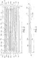
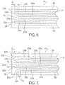
- Each pair of staggered endings 22a , 22b and 23a , 23b may be separated by one or more intervening reinforcement endings 22 or 23 , which are generally aligned with adjacent endings 22 or 23 to provide a local non-staggered arrangement of endings 22 or 23 , such as is shown generally in FIGS. 6 and 8C . It is also contemplated that two adjacent pairs of staggered reinforcement endings 22 , 23 may share an ending 22 or 23 , such as is shown in FIG. 2 for example, where adjacent reinforcement pairs 40 1 and 40 2 having staggered endings 22 , 23 share endings 22a and 23a , while pairs 40 2 and 40 3 share endings 22b and 23b .
- a staggered arrangement of endings 22 , 23 may also be described as providing one or more undulations 42 .
- two or more pairs of staggered endings 22 , 23 may result in an undulation 42 , which generally comprises a discontinuity along an arrangement of endings 22 , 23 that may form a recess or protrusion comprising one or more endings 22 , 23 .
- an undulation 42 is associated with two pairs of adjacent reinforcement endings 22, 23 , wherein the first pair provides an offset ⁇ in a direction inward or outward patch 15 and the subsequent pair provides an offset ⁇ extending in the other direction, so that an inward-outward or outward-inward undulation is provided.
- each ending 22 , 23 forms an undulation 42 because the patch 15 includes a 1x1 alternating arrangement of endings 22a, 22b and 23a , 23b , respectively.
- FIG. 6 generally shows a single undulation 42 forming a recess along the staggered arrangement of reinforcements 22 , while two undulations are provided in FIG. 7 , With reference to FIGS, 8A-8D , recessed and protruding undulations 42 are shown.
- An undulation 42 may or may not be symmetrical, meaning that the two offset distances ⁇ may not be equal.
- an undulation 42 may comprise two or more offsets ⁇ .
- the undulations 42 in FIG. 2 and 5 each include three (3) reinforcement endings 22 or 23 ( i .
- each undulation 42 comprises a 22b , 22a , 22b , 22a , 22b arrangement).
- the undulations 42 of FIGS. 8A-8C are each formed from four (4) reinforcement endings 22 or 23 .
- a staggered arrangement comprises an alternating arrangement of endings 22 or 23 , when generally including a plurality of undulations 42 .
- An alternating arrangement of endings is generally shown in various embodiments in FIGS. 2 , 5 , 7 , and 8A -8D .
- the alternating staggered arrangement may be arbitrary or systematic and continuous or intermittent, such as along a width of patch 15 .
- the staggered arrangement of endings 22 , 23 includes endings that are each positioned axially along a lengthwise direction of the corresponding reinforcement 20 .
- reinforcements 20 are longitudinally displaced with respect to other reinforcements 20 .
- the ends of particular reinforcements 20 may be longitudinally displaced with respect to each other as measured from a plane perpendicularly intersecting the longitudinal or axial axis of reinforcements 20 , such as a linear end 22 , 23 of patch 15 .
- longitudinal displacement is also termed axial displacement.
- the reinforcements 20 have a length L R that defines first 22 and second 23 respective reinforcement ends.
- an end 22a of a first reinforcement 20a may be longitudinally displaced with respect to end 22b of second reinforcement 20b , such as by distance ⁇ .
- the offset reinforcements 20a , 20b may be directly adjacent to each other.
- each adjacently positioned reinforcement 20a , 20b may be offset with respect to the prior reinforcement 20 , such as is shown in FIGS. 2 , 5 , 7 , 8A , and 8B .
- the adjacently positioned reinforcements 20a , 20b need necessarily be offset, such as is shown in a particular embodiment in FIG. 6 . Accordingly, two pairs of offset adjacent reinforcements 20a , 20b , may be provided, where one or more reinforcements 20 are placed between the two pairs, as shown in example in FIG. 6 .
- the tire patch 15 may include particular reinforcements 20 where ends 22 are aligned, i . e ., not axially offset.
- respective ends 23a , 23b of the reinforcements 20a , 20b may also be axially offset by the same or different amounts. In this manner, the reinforcements 20 of the tire patch 15 are unevenly spaced or staggered in the axial direction.
- stagger arrangements of endings 22 , 23 may be achieved when the length L R of individual reinforcements 20 are substantially identical.
- the offset ⁇ between reinforcements 20 may be implemented by axially shifting one reinforcement 20a with respect to another reinforcement 20b .
- the offset on one side of the tire patch 15 is directly proportional to the offset on the distal side of the tire patch 15 .
- the midpoints of each of the respective reinforcements 20a , 20b will be offset from each other when compared to a centerline axis of the tire patch 15 .
- the length L R of one reinforcement 20a may differ with respect to the length L R of another reinforcement 20b , such as shown is in FIG. 2 .
- Axial displacement may thus be implemented by aligning the midpoints of the reinforcements 20a , 20b , where the difference in reinforcement lengths will generally be directly proportional to offset ⁇ 1 . It is to be construed that any manner of axially displacing the reinforcements 20 within the tire patch 15 may be chosen with sound engineering judgment.
- the offset between multiple sets of adjacently positioned reinforcements 20 may vary.
- the offset between one set of adjacently positioned reinforcements 20 may be substantially zero, while that of another set may be significantly greater than zero, designated by ⁇ . It is noted that any pattern of fashioning the variation in offsets may be chosen without departing from the intended scope of coverage of the embodiments of the subject invention.
- the offset spacing of a first set of adjacently positioned reinforcements 20 may be non-zero and so have a value designated by ⁇ 1 .
- Subsequently positioned sets of reinforcements 20 may be offset by a different amount, shown generally at ⁇ 2 , which may be greater or less than the first offset ⁇ 1 .
- each offset ⁇ may range from between 0 inch to 0.5 inch. Although any size offset may exist, offsets greater than 0.5 inch may be selected without departing from the intended scope of coverage of the embodiments of the subject invention. It will be appreciated by persons of ordinary skill in the art that any number of axially displaced sets of cords and any difference in axial displacement between cords may be chosen as is suitable for repairing damaged tires 10 .
- the reinforcement layer 16b formed along its ends to achieve a staggered arrangement of reinforcement endings 22 , 23 .
- the staggered end of a reinforcement layer 16b may be formed by cutting or shearing a profile or path along an end of the layer.
- Particular embodiments include any linearly staggered or alternating edge 44 , which may form a zigzag path as shown generally in FIGS. 8A and 8D , or a path representing a step function, as shown generally in FIG. 8C .
- the staggered arrangement is provided by adjacent pairs of endings 22 , 23 having the angled cross-cut, so to provide an undulation 42 or offset ⁇ .
- edge 44 include curvilinear paths, as shown in FIG. 8B , and any other path, whether patterned or arbitrary and continuous or intermittent. Other embodiments contemplate curved edges 44 or combinations of straight and curved edges 44 , of which any radius may be chosen. Still another embodiment may include irregularly or arbitrarily shaped edges 44 . Still, the reinforcement layer edge 44 may be fashioned having any contour. It will be readily seen that the ends 22, 23 of the reinforcements 20 may extend all of the way up to the edges of the reinforcement layer 16b , thereby substantially traversing the entire length L R of the reinforcement layer 16b . Changes in the substrate edge may therefore be either abrupt or gradual as determined by the offset of each reinforcement 20 within the reinforcing layer 16b . In one particular embodiment, the edge pattern may be scalloped including straight or curved undulations. However, any edge pattern may be chosen as is appropriate for use with the particular embodiments of the present invention.
- the distal edges of the reinforcing layers 16b , and/or the arrangement of reinforcements 20 and endings 22 , 23 within a patch 15 may be aligned or arranged symmetrically or asymmetrically about a lateral or longitudinal centerline of reinforcing layer 16b and/or patch 15 .
- the reinforcement endings 22 , 23 are equidistant from a transverse centerline axis, as illustrated in FIG. 2 .
- the distance between distal edges of the substrate when measured from the transverse centerline axis is different for asymmetrically configured patterns, such as is shown in FIGS. 8A-8D . All such variations are to be construed as falling within the scope of coverage of the embodiments of the present invention.
Landscapes
- Engineering & Computer Science (AREA)
- Mechanical Engineering (AREA)
- Tires In General (AREA)
Claims (15)
- Reifenpflaster (15) zur Reparatur eines zugehörigen Fahrzeugreifens (10), umfassend:einen Pflasterkörper (17), der dazu ausgebildet ist, einen Abschnitt des zugehörigen Fahrzeugreifens (10) zu überdecken, wobei der Pflasterkörper (17) durch eine Breite und eine sich quer zu der Breite zwischen zwei gegenüberliegenden Enden erstreckende Länge definiert ist, wobei der Pflasterkörper (17) eine Längsmittellinie (CL) aufweist, die sich quer über die Breite des Pflasterkörpers senkrecht zu der Länge des Pflasterkörpers erstreckt;eine Vielzahl von Verstärkungen (20), die wenigstens teilweise in dem Pflasterkörper (17) aufgenommen sind, um eine einzelne Schicht (16b) von Verstärkungen zu bilden, die in der Dicke des Pflasterkörpers angeordnet ist, wobei die einzelne Schicht (16b) von Verstärkungen eine einzelne Materiallage umfasst, die die Vielzahl von in einem elastomeren Substrat (21) angeordneten Verstärkungen umfasst, wobei jede Verstärkung der Vielzahl von Verstärkungen (20) eine sich zwischen einem ersten Verstärkungsende (22) und einem zweiten Verstärkungsende (23) erstreckende Länge besitzt, sodass jedes von dem ersten Verstärkungsende und dem zweiten Verstärkungsende weg von dem anderen von dem ersten Verstärkungsende und dem zweiten Verstärkungsende und der Längsmittellinie (CL) des Pflasterkörpers (17) gerichtet ist,wobei sich die Länge jeder Verstärkung der Vielzahl von Verstärkungen (20) in einer Richtung der Pflasterkörperlänge zwischen den beiden gegenüberliegenden Enden des Pflasterkörpers (17) erstreckt,dadurch gekennzeichnet, dass die Vielzahl von Verstärkungen (20) in Richtung der Breite des Pflasterkörpers (17) voneinander beabstandet und nebeneinanderliegend angeordnet sind, sodass die ersten Verstärkungsenden (22) in einer versetzten Anordnung angeordnet sind, wodurch erste Verstärkungsenden (22) so angeordnet sind, dass sie sich in Richtung der Pflasterkörperbreite erstrecken, sodass benachbarte erste Verstärkungsenden einer ersten Verstärkung und einer zweiten Verstärkung von jedem der zwei oder mehr benachbarten Paare von Verstärkungen der Vielzahl von Verstärkungen (20) ein Stück weit relativ zueinander in Richtung der Pflasterkörperlänge versetzt sind, sodass die benachbarten ersten Verstärkungsenden der ersten Verstärkung und zweiten Verstärkung von jedem der zwei oder mehr benachbarten Paare von Verstärkungen unterschiedlich weit von der Längsmittellinie (CL) des Pflasters angeordnet sind, um eine oder mehrere Wellenlinien entlang der versetzten Anordnung von ersten Verstärkungsenden zu bilden.
- Reifenpflaster (15) nach Anspruch 1, wobei die versetzte Anordnung von ersten Enden eine alternierende, versetzte Anordnung mit einer Vielzahl von Wellenlinien (42) von ersten Verstärkungsenden (22) umfasst.
- Reifenpflaster (15) nach Anspruch 1, wobei der Versatz mindestens 5 mm beträgt.
- Reifenpflaster (15) nach Anspruch 1, wobei die Länge jeder Verstärkung der Vielzahl von Verstärkungen (22) im Wesentlichen die gleiche Länge ist.
- Reifenpflaster (15) nach Anspruch 1, wobei die Vielzahl von Verstärkungen (22) in einer Verstärkungsschicht (16b) des Pflasters (17) enthalten sind.
- Reifenpflaster (15) nach Anspruch 1, wobei die Vielzahl von Verstärkungen (22) in der voneinander beabstandeten, nebeneinanderliegenden Anordnung parallel angeordnet sind.
- Reifenpflaster (15) nach Anspruch 1, wobei die Wellenlinie von ersten Verstärkungsenden durch vier oder mehr erste Verstärkungsenden gebildet wird.
- Reifenpflaster nach Anspruch 1, wobei die ersten Verstärkungsenden entlang eines Randes des Pflasterkörpers (17) angeordnet sind.
- Reifenpflaster nach Anspruch 1, wobei die einzelne Verstärkungsschicht zwischen einer oberen Polsterschicht und einer unteren Polsterschicht angeordnet ist.
- Reifenpflaster nach Anspruch 1, wobei der Versatz mindestens 10 mm beträgt.
- Reifenpflaster nach Anspruch 9, ferner umfassend eine Klebstoffschicht, die entlang einer Außenseite der unteren Polsterschicht angeordnet ist.
- Reifenpflaster nach Anspruch 1, wobei die Vielzahl von Verstärkungen (20) in einer voneinander beabstandeten, nebeneinanderliegenden Anordnung in Richtung der Breite des Pflasterkörpers (17) angeordnet sind, sodass die zweiten Verstärkungsenden in einer versetzten Anordnung angeordnet sind, wodurch sich die Anordnung von zweiten Verstärkungsenden in Richtung der Pflasterkörperbreite erstreckt, sodass benachbarte zweite Verstärkungsenden der ersten Verstärkung und einer zweiten Verstärkung von jedem der zwei oder mehr benachbarten Paare von Verstärkungen der Vielzahl von Verstärkungen ein Stück weit relativ zueinander in Richtung der Pflasterkörperlänge versetzt sind, sodass die benachbarten zweiten Verstärkungsenden der ersten Verstärkung und der zweiten Verstärkung von jedem der zwei oder mehr benachbarten Paare von Verstärkungen unterschiedlich weit von der Längsmittellinie des Pflasters angeordnet sind, um eine oder mehrere Wellenlinien entlang der versetzten Anordnung der zweiten Verstärkungsenden zu bilden.
- Reifenpflaster nach Anspruch 12, wobei die ersten Verstärkungsenden und die zweiten Verstärkungsenden asymmetrisch zueinander in Bezug auf die Längsmittellinie (CL) des Pflasters angeordnet sind, sodass der Abstand zwischen dem ersten Verstärkungsende und der Längsmittellinie (CL) des Pflasterkörpers (17) von dem Abstand zwischen dem zweiten Verstärkungsende in Bezug auf die Längsmittellinie (CL) des Pflasterkörpers (17) für jede Verstärkung verschieden ist.
- Geflickter Reifen (10), umfassend:einen Reifen mit einer Innenseite und einer Außenseite;ein Reifenpflaster (15) nach einem der Ansprüche 1 bis 13, das auf die Innenseite oder die Außenseite aufgebracht ist.
- Geflickter Reifen (10) nach Anspruch 14, wobei der Reifen Originalverstärkungen aufweist, die sich in einer radialen Richtung des Reifens erstrecken,
wobei sich die Länge jeder Verstärkung der Vielzahl von Verstärkungen (20) im Wesentlichen in der gleichen radialen Richtung erstreckt wie die Originalverstärkungen.
Applications Claiming Priority (1)
| Application Number | Priority Date | Filing Date | Title |
|---|---|---|---|
| PCT/US2008/068567 WO2009157944A2 (en) | 2008-06-27 | 2008-06-27 | Patch having reinforcements with staggered ends |
Publications (3)
| Publication Number | Publication Date |
|---|---|
| EP2318201A2 EP2318201A2 (de) | 2011-05-11 |
| EP2318201A4 EP2318201A4 (de) | 2013-05-29 |
| EP2318201B1 true EP2318201B1 (de) | 2019-05-22 |
Family
ID=41445136
Family Applications (1)
| Application Number | Title | Priority Date | Filing Date |
|---|---|---|---|
| EP08772154.4A Not-in-force EP2318201B1 (de) | 2008-06-27 | 2008-06-27 | Verstärkungen mit versetzten enden aufweisender flicken |
Country Status (6)
| Country | Link |
|---|---|
| US (1) | US8720510B2 (de) |
| EP (1) | EP2318201B1 (de) |
| JP (1) | JP5378509B2 (de) |
| CN (1) | CN102066095B (de) |
| BR (1) | BRPI0822863A8 (de) |
| WO (1) | WO2009157944A2 (de) |
Families Citing this family (4)
| Publication number | Priority date | Publication date | Assignee | Title |
|---|---|---|---|---|
| WO2012053226A1 (ja) * | 2010-10-22 | 2012-04-26 | 株式会社ブリヂストン | ラジアルタイヤの修理方法、修理済みラジアルタイヤおよびパッチラバー |
| EP2676788A4 (de) * | 2011-02-17 | 2015-11-25 | Bridgestone Corp | Kautschukpflaster zur reparatur von gürtelreifen, verfahren zur reparatur von gürtelreifen damit und reparierter gürtelreifen |
| US11554562B2 (en) | 2018-09-18 | 2023-01-17 | Bridgestone Americas Tire Operations, Llc | Method for repairing tire tread |
| JP2023170267A (ja) * | 2022-05-18 | 2023-12-01 | 株式会社ブリヂストン | 修理済み空気入りタイヤの製造方法 |
Citations (1)
| Publication number | Priority date | Publication date | Assignee | Title |
|---|---|---|---|---|
| US3282319A (en) * | 1965-08-13 | 1966-11-01 | Myers Ind Inc | Tire patch |
Family Cites Families (79)
| Publication number | Priority date | Publication date | Assignee | Title |
|---|---|---|---|---|
| US1591817A (en) | 1924-08-15 | 1926-07-06 | Ke Hawke Mfg Co | Process of repairing pneumatic-tire casings |
| FR634317A (fr) | 1927-05-12 | 1928-02-16 | Immediat L | Perfectionnement aux pièces en caoutchouc utilisées notamment pour la réparation des chambres à air |
| SU41858A1 (ru) | 1934-04-25 | 1935-02-28 | Г.И. Зотов | Устройство дл обеспечени плотного прилегани заплатки к ремонтируемой покрышке во врем вулканизации |
| US2547487A (en) | 1947-04-10 | 1951-04-03 | Penney Frederic Houghton | Separate and individual pressure adhesive pieces with means of application and attachment of same |
| FR972637A (fr) | 1948-08-26 | 1951-02-01 | Otto Gruber & Co | Pièce de réparation pour objets en caoutchouc ou caoutchoutés, tels que bandages d'automobiles et de vélocipèdes |
| US2585635A (en) | 1949-08-13 | 1952-02-12 | Harry A Dibble | Means for the repair of punctured tires |
| US2596179A (en) | 1951-01-04 | 1952-05-13 | B B Chem Co | Supported adhesive sheet material unit and method of making the same |
| US2833327A (en) | 1953-08-28 | 1958-05-06 | Boyce Reginald Donovan | Adhesive repair patches |
| GB839087A (en) | 1957-11-21 | 1960-06-29 | Romac Ind Ltd | Improvements in or relating to adhesive repair patches |
| FR1203408A (fr) | 1958-09-30 | 1960-01-18 | Pastilles de réparation, notamment pour chambres à air de pneumatiques | |
| DE1141552B (de) | 1959-11-13 | 1962-12-20 | Stahlgruber Gruber & Co Otto | Reparaturpflaster fuer Fahrzeugreifen |
| FR1226595A (fr) | 1959-02-24 | 1960-07-13 | Mft Fr Pneumatiques Michelin | Perfectionnement aux nappes de renforcement des enveloppes de pneumatiques |
| US3004580A (en) | 1960-07-19 | 1961-10-17 | Technical Rubber Company Inc | Multi-ply tire repair unit |
| FR1287560A (fr) | 1961-02-01 | 1962-03-16 | Kleber Colombes | Perfectionnements aux enveloppes de pneumatiques |
| NL275083A (de) | 1961-03-22 | |||
| US3095342A (en) | 1961-12-15 | 1963-06-25 | Kraly John | Tire repair insert |
| NL290963A (de) | 1962-04-09 | |||
| GB974268A (en) * | 1962-07-31 | 1964-11-04 | Tyresoles Nederland N V | Improvements in or relating to repair plasters for motor-car tyres |
| DE1225981B (de) * | 1962-07-31 | 1966-09-29 | Tyresoles Nederland N V | Reparaturpflaster fuer Autoreifen |
| DE1244003B (de) | 1962-09-28 | 1967-07-06 | En Commandite Par Actions Mich | Reparaturpflaster fuer Luftreifen mit radial angeordneten Karkassenfaeden oder -draehten |
| US3332466A (en) | 1962-10-24 | 1967-07-25 | Goodyear Tire & Rubber | Spiral cord center patch |
| US3133586A (en) | 1962-11-15 | 1964-05-19 | Goodyear Tire & Rubber | Repair element for tire |
| US3160194A (en) | 1963-03-28 | 1964-12-08 | Goodyear Tire & Rubber | Tire patch |
| FR1388009A (fr) | 1963-12-23 | 1965-02-05 | Michelin & Cie | Emplâtre de réparation d'enveloppes de pneumatiques du type sans chambre à air |
| DE1255525B (de) | 1964-06-09 | 1967-11-30 | Fritz Hesselbein Chem Fab | Reparaturpflaster fuer beschaedigte Luftreifen von Kraftfahrzeugen |
| US3306332A (en) | 1965-03-29 | 1967-02-28 | Gen Tire & Rubber Co | Repairing of radial cord tires |
| US3448784A (en) | 1966-11-18 | 1969-06-10 | Caterpillar Tractor Co | Tire patch for repairing pneumatic tires |
| AT308576B (de) | 1968-02-02 | 1973-07-10 | Stahlgruber Gruber & Co Otto | Reparaturkörper für Kraftfahrzeugreifen |
| DE1780071A1 (de) | 1968-07-30 | 1972-06-22 | Fritz Hesselbein Chem Fab | Reparaturpflaster fuer Luftreifen |
| DE1912469A1 (de) * | 1969-03-12 | 1970-09-24 | Stahlgruber Gruber & Co Otto | Reparaturpflaster |
| US3719218A (en) * | 1971-03-08 | 1973-03-06 | Monsanto Co | Tire with belt having scalloped edges |
| US3730247A (en) * | 1971-05-24 | 1973-05-01 | J White | Repair patches and methods |
| DE2936165A1 (de) | 1979-09-07 | 1981-03-19 | Stahlgruber Otto Gruber GmbH & Co, 8000 MÜnchen | Pflaster fuer die reparatur von fahrzeugreifen |
| US4317692A (en) | 1980-04-21 | 1982-03-02 | Niconchuk Alec W | Inside repair for tubeless tire and method for applying same |
| US4408649A (en) | 1980-07-07 | 1983-10-11 | Technical Rubber Company, Inc. | Tire repair unit |
| US4285382A (en) | 1980-07-10 | 1981-08-25 | Dirocco Jobbie | Tire repair patch |
| FR2496004A1 (fr) | 1980-12-16 | 1982-06-18 | Michelin & Cie | Procede de collage de deux corps en caoutchouc, notamment pour rechaper ou reparer un pneumatique |
| US4375231A (en) | 1981-03-02 | 1983-03-01 | Vulcan Equipment Company, Ltd. | Tire repair construction and method |
| US4333508A (en) | 1981-06-01 | 1982-06-08 | Dirocco Jobbie | Tire repair patch for sidewall and bead repairs |
| US4399854A (en) * | 1981-06-15 | 1983-08-23 | Dirocco Jobbie | Tire repair patch and method of manufacture |
| US4385651A (en) | 1981-08-17 | 1983-05-31 | Arquilla Jack V | Tire repair patch |
| US4434832A (en) | 1983-03-21 | 1984-03-06 | The Firestone Tire & Rubber Company | Room temperature curable tire patch |
| US4696332A (en) | 1984-02-28 | 1987-09-29 | The Firestone Tire & Rubber Company | Elastomer free grid reinforcement of pressurable elastomer repaired articles |
| US4718469A (en) | 1984-02-28 | 1988-01-12 | The Firestone Tire & Rubber Company | Preformed plug-tire repair |
| US4923543A (en) | 1984-02-28 | 1990-05-08 | Bridgestone/Firestone, Inc. | Preformed plug - tire repair |
| US4540035A (en) * | 1984-03-28 | 1985-09-10 | Simon Roberts | Tire repair patch |
| ZA852687B (en) | 1984-04-13 | 1986-01-29 | Perfect Equip Corp | Plug patch for radial tyres |
| DE3515944A1 (de) | 1985-05-03 | 1986-11-06 | Continental Gummi-Werke Ag, 3000 Hannover | Fahrzeugluftreifen |
| IT1213622B (it) | 1987-01-21 | 1989-12-29 | Rfp Srl | Toppa trapezoidale per riparare rotture delle corde matalliche sui fianchi dei copertoni dei pneumatici radiali senza camera d'aria |
| ES2088859T3 (es) | 1987-02-23 | 1996-10-01 | Rfp Srl | Tapon para la reparacion o reconstruccion de neumaticos radiales. |
| US4836930A (en) | 1988-02-18 | 1989-06-06 | Hill William R | Method of repairing vehicular tires |
| JP2625004B2 (ja) | 1988-07-02 | 1997-06-25 | ランデス株式会社 | 軟弱地盤の水路施工方法及びそれに用いる水路ブロック |
| EP0353313B1 (de) | 1988-07-27 | 1993-04-28 | R.F.P. S.r.l. Ricostruzione Fascia Prestampata | Traperförmiges Pflaster für die Reparatur von Schäden der metallischen Kordfäden an den Seitenwänden von radialen Reifen mit oder ohne Schlauch und Herstellungsverfahren |
| SU1648807A1 (ru) | 1989-04-26 | 1991-05-15 | Научно-исследовательский институт крупногабаритных шин | Пластырь дл ремонта пневматических шин |
| DE3926946A1 (de) | 1989-07-06 | 1991-01-10 | Stahlgruber Gruber & Co Otto | Verfahren und vorrichtung zur reparatur von gegenstaenden aus gummi, wie foerderbaender, reifen oder dgl. |
| SU1708666A1 (ru) | 1990-01-03 | 1992-01-30 | Научно-исследовательский институт крупногабаритных шин | Способ ремонта местных повреждений шин |
| US5335707A (en) | 1991-02-15 | 1994-08-09 | Sumitomo Rubber Industries, Ltd. | High speed heavy duty cross ply tire |
| US5247981A (en) | 1991-03-06 | 1993-09-28 | Benedicto Jr Isidro G | Method of major sectional tire repair and product thereof |
| CA2123003A1 (en) | 1991-11-06 | 1993-05-13 | Dennis M. Kay | Occlusive wound dressing and applicator |
| JPH07137155A (ja) * | 1993-11-12 | 1995-05-30 | Bridgestone Corp | ラジアルタイヤ貫通傷の修理方法及び修理パッチ |
| NL9302004A (nl) | 1993-11-19 | 1995-06-16 | Wilhelmus Maria Cornelis Aarts | Banden voorzien van reparatiepleister. |
| JPH07172123A (ja) * | 1993-12-21 | 1995-07-11 | Bridgestone Corp | タイヤ修理用のパッチ |
| JPH08244124A (ja) | 1995-03-10 | 1996-09-24 | Bridgestone Corp | チューブレス空気入りタイヤ修理用パッチ |
| DE29610697U1 (de) | 1996-06-18 | 1996-09-19 | Stahlgruber Otto Gruber GmbH & Co, 81675 München | Reparaturpflaster für Luftreifen |
| US5830295A (en) | 1997-02-14 | 1998-11-03 | The Goodyear Tire & Rubber Company | Pneumatic tire with belt structure including reinforced gum strips |
| US6026878A (en) | 1997-05-29 | 2000-02-22 | The Goodyear Tire & Rubber Company | Inextensible high temperature resistant tire |
| ZA9810315B (en) | 1997-11-27 | 1999-05-18 | Bekaert Sa Nv | Steel cord with spatially waved elements |
| US6426129B1 (en) | 1998-03-09 | 2002-07-30 | Bfs Diversified Products, Llc | Adhesive rubber article having scored released liner and guide to facilitate field application and related methods |
| US6386255B1 (en) | 1999-07-30 | 2002-05-14 | The Goodyear Tire & Rubber Company | Tire repair patch including bis-imide compound |
| RU2176954C1 (ru) | 2000-03-21 | 2001-12-20 | Виленц Виктор Семенович | Способ ремонта изделий из полимерных материалов |
| CA2354284C (en) | 2001-07-27 | 2008-07-15 | R.F.P. S.R.L. - Ricostruzione Fascia Prestampata | Technique for the partial substitution of damaged metal cords in the sidewalls of medium and large radial tires and the means to permit their substitution |
| US7027877B2 (en) | 2001-08-23 | 2006-04-11 | Zoll Medical Corporation | Method of applying defibrilator electrode pad with folded release sheet |
| CN2508947Y (zh) * | 2001-12-25 | 2002-09-04 | 肖新中 | 汽车轮胎钢丝加心补片 |
| BRPI0407933A (pt) * | 2003-03-03 | 2006-02-21 | Technologie Michelin E Micheli | pneumático |
| CN2633560Y (zh) * | 2003-03-30 | 2004-08-18 | 刘传立 | 常温硫化包趾口复合帘线修补带 |
| JP4851338B2 (ja) | 2003-11-28 | 2012-01-11 | コロプラスト アクティーゼルスカブ | ドレッシング物品 |
| US7712413B2 (en) | 2004-08-20 | 2010-05-11 | Hewlett-Packard Development Company, L.P. | Printable cover systems for articles |
| DE202005003662U1 (de) | 2005-03-08 | 2005-06-02 | Stahlgruber Otto Gruber Gmbh & Co Kg | Flicken zur Reparaturvulkanisation von Reifen |
| EP1864786A1 (de) | 2005-03-30 | 2007-12-12 | Bridgestone Corporation | Verfahren zur reparatur eines innenflächenteils eines luftreifens und relevantes innenflächenteilreparaturmaterial |
-
2008
- 2008-06-27 EP EP08772154.4A patent/EP2318201B1/de not_active Not-in-force
- 2008-06-27 US US13/001,412 patent/US8720510B2/en active Active
- 2008-06-27 WO PCT/US2008/068567 patent/WO2009157944A2/en not_active Ceased
- 2008-06-27 JP JP2011514562A patent/JP5378509B2/ja not_active Expired - Fee Related
- 2008-06-27 CN CN200880129966.8A patent/CN102066095B/zh not_active Expired - Fee Related
- 2008-06-27 BR BRPI0822863A patent/BRPI0822863A8/pt not_active IP Right Cessation
Patent Citations (1)
| Publication number | Priority date | Publication date | Assignee | Title |
|---|---|---|---|---|
| US3282319A (en) * | 1965-08-13 | 1966-11-01 | Myers Ind Inc | Tire patch |
Also Published As
| Publication number | Publication date |
|---|---|
| US20110108177A1 (en) | 2011-05-12 |
| CN102066095A (zh) | 2011-05-18 |
| JP2011524829A (ja) | 2011-09-08 |
| EP2318201A4 (de) | 2013-05-29 |
| JP5378509B2 (ja) | 2013-12-25 |
| WO2009157944A3 (en) | 2010-05-20 |
| BRPI0822863A2 (pt) | 2015-06-30 |
| US8720510B2 (en) | 2014-05-13 |
| EP2318201A2 (de) | 2011-05-11 |
| WO2009157944A2 (en) | 2009-12-30 |
| CN102066095B (zh) | 2015-03-11 |
| BRPI0822863A8 (pt) | 2016-01-05 |
Similar Documents
| Publication | Publication Date | Title |
|---|---|---|
| KR101974461B1 (ko) | 공기입 타이어 | |
| US10518588B2 (en) | Pneumatic tire | |
| US20180056723A1 (en) | Crown reinforcement for a tire for a heavy-duty civil engineering vehicle | |
| CN108202565B (zh) | 充气轮胎,胎面带,及包含刀槽花纹的胎面块,及制造刀槽花纹的薄层板 | |
| US8720510B2 (en) | Patch having reinforcements with staggered ends | |
| CN106132726B (zh) | 翻新轮胎 | |
| WO2015174413A1 (ja) | 更生タイヤ | |
| US20130220503A1 (en) | Method for repairing radial tire, repaired radial tire, and patch rubber | |
| JP2011525869A (ja) | 一体形タイヤ部分補修 | |
| RU2530200C2 (ru) | Протектор шины, имеющий полости и прорези | |
| US20110114250A1 (en) | Patching having discontinuous engagement to the tire | |
| CN104812593B (zh) | 农用轮胎 | |
| US20170326920A1 (en) | Tyre and a method for manufacturing an annular | |
| EP1516752B1 (de) | Reifenwulst-Aufbau | |
| CN102076511B (zh) | 用于轮胎修复的损坏增强件的端部准备 | |
| US20190263182A1 (en) | Aircraft Tire Crown Reinforcement | |
| US20110146887A1 (en) | Tire ply and method of manufacture | |
| RU2458795C1 (ru) | Заплата, содержащая армирующие элементы, со ступенчато смещенными концами | |
| KR101998968B1 (ko) | 중하중용 타이어 | |
| FR2793730A1 (fr) | Construction amelioree de bande de roulement et de flanc d'un pneumatique | |
| KR20200051275A (ko) | 공기입 타이어 및 이의 제조방법 | |
| KR20120016879A (ko) | 차량용 공기입 타이어 |
Legal Events
| Date | Code | Title | Description |
|---|---|---|---|
| PUAI | Public reference made under article 153(3) epc to a published international application that has entered the european phase |
Free format text: ORIGINAL CODE: 0009012 |
|
| 17P | Request for examination filed |
Effective date: 20101229 |
|
| AK | Designated contracting states |
Kind code of ref document: A2 Designated state(s): AT BE BG CH CY CZ DE DK EE ES FI FR GB GR HR HU IE IS IT LI LT LU LV MC MT NL NO PL PT RO SE SI SK TR |
|
| AX | Request for extension of the european patent |
Extension state: AL BA MK RS |
|
| DAX | Request for extension of the european patent (deleted) | ||
| RAP1 | Party data changed (applicant data changed or rights of an application transferred) |
Owner name: MICHELIN RECHERCHE ET TECHNIQUE S.A. Owner name: COMPAGNIE GENERALE DES ETABLISSEMENTS MICHELIN |
|
| A4 | Supplementary search report drawn up and despatched |
Effective date: 20130503 |
|
| RIC1 | Information provided on ipc code assigned before grant |
Ipc: B29C 73/00 20060101AFI20130425BHEP |
|
| RAP1 | Party data changed (applicant data changed or rights of an application transferred) |
Owner name: MICHELIN RECHERCHE ET TECHNIQUE S.A. |
|
| RAP1 | Party data changed (applicant data changed or rights of an application transferred) |
Owner name: COMPAGNIE GENERALE DES ETABLISSEMENTS MICHELIN |
|
| STAA | Information on the status of an ep patent application or granted ep patent |
Free format text: STATUS: EXAMINATION IS IN PROGRESS |
|
| 17Q | First examination report despatched |
Effective date: 20170822 |
|
| RAP1 | Party data changed (applicant data changed or rights of an application transferred) |
Owner name: COMPAGNIE GENERALE DES ETABLISSEMENTS MICHELIN |
|
| REG | Reference to a national code |
Ref country code: DE Ref legal event code: R079 Ref document number: 602008060172 Country of ref document: DE Free format text: PREVIOUS MAIN CLASS: B29C0073000000 Ipc: B29C0073100000 |
|
| GRAP | Despatch of communication of intention to grant a patent |
Free format text: ORIGINAL CODE: EPIDOSNIGR1 |
|
| STAA | Information on the status of an ep patent application or granted ep patent |
Free format text: STATUS: GRANT OF PATENT IS INTENDED |
|
| RIC1 | Information provided on ipc code assigned before grant |
Ipc: B29C 73/10 20060101AFI20181120BHEP Ipc: B29L 30/00 20060101ALN20181120BHEP |
|
| RIC1 | Information provided on ipc code assigned before grant |
Ipc: B29L 30/00 20060101ALN20181203BHEP Ipc: B29C 73/10 20060101AFI20181203BHEP |
|
| INTG | Intention to grant announced |
Effective date: 20181217 |
|
| GRAS | Grant fee paid |
Free format text: ORIGINAL CODE: EPIDOSNIGR3 |
|
| GRAA | (expected) grant |
Free format text: ORIGINAL CODE: 0009210 |
|
| STAA | Information on the status of an ep patent application or granted ep patent |
Free format text: STATUS: THE PATENT HAS BEEN GRANTED |
|
| AK | Designated contracting states |
Kind code of ref document: B1 Designated state(s): AT BE BG CH CY CZ DE DK EE ES FI FR GB GR HR HU IE IS IT LI LT LU LV MC MT NL NO PL PT RO SE SI SK TR |
|
| REG | Reference to a national code |
Ref country code: GB Ref legal event code: FG4D |
|
| REG | Reference to a national code |
Ref country code: CH Ref legal event code: EP |
|
| REG | Reference to a national code |
Ref country code: IE Ref legal event code: FG4D |
|
| REG | Reference to a national code |
Ref country code: DE Ref legal event code: R096 Ref document number: 602008060172 Country of ref document: DE |
|
| REG | Reference to a national code |
Ref country code: AT Ref legal event code: REF Ref document number: 1135578 Country of ref document: AT Kind code of ref document: T Effective date: 20190615 |
|
| REG | Reference to a national code |
Ref country code: NL Ref legal event code: FP |
|
| REG | Reference to a national code |
Ref country code: LT Ref legal event code: MG4D |
|
| PG25 | Lapsed in a contracting state [announced via postgrant information from national office to epo] |
Ref country code: NO Free format text: LAPSE BECAUSE OF FAILURE TO SUBMIT A TRANSLATION OF THE DESCRIPTION OR TO PAY THE FEE WITHIN THE PRESCRIBED TIME-LIMIT Effective date: 20190822 Ref country code: FI Free format text: LAPSE BECAUSE OF FAILURE TO SUBMIT A TRANSLATION OF THE DESCRIPTION OR TO PAY THE FEE WITHIN THE PRESCRIBED TIME-LIMIT Effective date: 20190522 Ref country code: HR Free format text: LAPSE BECAUSE OF FAILURE TO SUBMIT A TRANSLATION OF THE DESCRIPTION OR TO PAY THE FEE WITHIN THE PRESCRIBED TIME-LIMIT Effective date: 20190522 Ref country code: SE Free format text: LAPSE BECAUSE OF FAILURE TO SUBMIT A TRANSLATION OF THE DESCRIPTION OR TO PAY THE FEE WITHIN THE PRESCRIBED TIME-LIMIT Effective date: 20190522 Ref country code: ES Free format text: LAPSE BECAUSE OF FAILURE TO SUBMIT A TRANSLATION OF THE DESCRIPTION OR TO PAY THE FEE WITHIN THE PRESCRIBED TIME-LIMIT Effective date: 20190522 Ref country code: PT Free format text: LAPSE BECAUSE OF FAILURE TO SUBMIT A TRANSLATION OF THE DESCRIPTION OR TO PAY THE FEE WITHIN THE PRESCRIBED TIME-LIMIT Effective date: 20190922 Ref country code: LT Free format text: LAPSE BECAUSE OF FAILURE TO SUBMIT A TRANSLATION OF THE DESCRIPTION OR TO PAY THE FEE WITHIN THE PRESCRIBED TIME-LIMIT Effective date: 20190522 |
|
| PG25 | Lapsed in a contracting state [announced via postgrant information from national office to epo] |
Ref country code: BG Free format text: LAPSE BECAUSE OF FAILURE TO SUBMIT A TRANSLATION OF THE DESCRIPTION OR TO PAY THE FEE WITHIN THE PRESCRIBED TIME-LIMIT Effective date: 20190822 Ref country code: LV Free format text: LAPSE BECAUSE OF FAILURE TO SUBMIT A TRANSLATION OF THE DESCRIPTION OR TO PAY THE FEE WITHIN THE PRESCRIBED TIME-LIMIT Effective date: 20190522 Ref country code: GR Free format text: LAPSE BECAUSE OF FAILURE TO SUBMIT A TRANSLATION OF THE DESCRIPTION OR TO PAY THE FEE WITHIN THE PRESCRIBED TIME-LIMIT Effective date: 20190823 |
|
| REG | Reference to a national code |
Ref country code: AT Ref legal event code: MK05 Ref document number: 1135578 Country of ref document: AT Kind code of ref document: T Effective date: 20190522 |
|
| PG25 | Lapsed in a contracting state [announced via postgrant information from national office to epo] |
Ref country code: SK Free format text: LAPSE BECAUSE OF FAILURE TO SUBMIT A TRANSLATION OF THE DESCRIPTION OR TO PAY THE FEE WITHIN THE PRESCRIBED TIME-LIMIT Effective date: 20190522 Ref country code: CZ Free format text: LAPSE BECAUSE OF FAILURE TO SUBMIT A TRANSLATION OF THE DESCRIPTION OR TO PAY THE FEE WITHIN THE PRESCRIBED TIME-LIMIT Effective date: 20190522 Ref country code: RO Free format text: LAPSE BECAUSE OF FAILURE TO SUBMIT A TRANSLATION OF THE DESCRIPTION OR TO PAY THE FEE WITHIN THE PRESCRIBED TIME-LIMIT Effective date: 20190522 Ref country code: EE Free format text: LAPSE BECAUSE OF FAILURE TO SUBMIT A TRANSLATION OF THE DESCRIPTION OR TO PAY THE FEE WITHIN THE PRESCRIBED TIME-LIMIT Effective date: 20190522 Ref country code: DK Free format text: LAPSE BECAUSE OF FAILURE TO SUBMIT A TRANSLATION OF THE DESCRIPTION OR TO PAY THE FEE WITHIN THE PRESCRIBED TIME-LIMIT Effective date: 20190522 Ref country code: AT Free format text: LAPSE BECAUSE OF FAILURE TO SUBMIT A TRANSLATION OF THE DESCRIPTION OR TO PAY THE FEE WITHIN THE PRESCRIBED TIME-LIMIT Effective date: 20190522 |
|
| REG | Reference to a national code |
Ref country code: CH Ref legal event code: PL |
|
| REG | Reference to a national code |
Ref country code: DE Ref legal event code: R097 Ref document number: 602008060172 Country of ref document: DE |
|
| PG25 | Lapsed in a contracting state [announced via postgrant information from national office to epo] |
Ref country code: IT Free format text: LAPSE BECAUSE OF FAILURE TO SUBMIT A TRANSLATION OF THE DESCRIPTION OR TO PAY THE FEE WITHIN THE PRESCRIBED TIME-LIMIT Effective date: 20190522 Ref country code: MC Free format text: LAPSE BECAUSE OF FAILURE TO SUBMIT A TRANSLATION OF THE DESCRIPTION OR TO PAY THE FEE WITHIN THE PRESCRIBED TIME-LIMIT Effective date: 20190522 |
|
| PLBE | No opposition filed within time limit |
Free format text: ORIGINAL CODE: 0009261 |
|
| REG | Reference to a national code |
Ref country code: BE Ref legal event code: MM Effective date: 20190630 |
|
| STAA | Information on the status of an ep patent application or granted ep patent |
Free format text: STATUS: NO OPPOSITION FILED WITHIN TIME LIMIT |
|
| PG25 | Lapsed in a contracting state [announced via postgrant information from national office to epo] |
Ref country code: TR Free format text: LAPSE BECAUSE OF FAILURE TO SUBMIT A TRANSLATION OF THE DESCRIPTION OR TO PAY THE FEE WITHIN THE PRESCRIBED TIME-LIMIT Effective date: 20190522 |
|
| 26N | No opposition filed |
Effective date: 20200225 |
|
| GBPC | Gb: european patent ceased through non-payment of renewal fee |
Effective date: 20190822 |
|
| PG25 | Lapsed in a contracting state [announced via postgrant information from national office to epo] |
Ref country code: PL Free format text: LAPSE BECAUSE OF FAILURE TO SUBMIT A TRANSLATION OF THE DESCRIPTION OR TO PAY THE FEE WITHIN THE PRESCRIBED TIME-LIMIT Effective date: 20190522 Ref country code: IE Free format text: LAPSE BECAUSE OF NON-PAYMENT OF DUE FEES Effective date: 20190627 |
|
| PG25 | Lapsed in a contracting state [announced via postgrant information from national office to epo] |
Ref country code: CH Free format text: LAPSE BECAUSE OF NON-PAYMENT OF DUE FEES Effective date: 20190630 Ref country code: SI Free format text: LAPSE BECAUSE OF FAILURE TO SUBMIT A TRANSLATION OF THE DESCRIPTION OR TO PAY THE FEE WITHIN THE PRESCRIBED TIME-LIMIT Effective date: 20190522 Ref country code: BE Free format text: LAPSE BECAUSE OF NON-PAYMENT OF DUE FEES Effective date: 20190630 Ref country code: LI Free format text: LAPSE BECAUSE OF NON-PAYMENT OF DUE FEES Effective date: 20190630 Ref country code: LU Free format text: LAPSE BECAUSE OF NON-PAYMENT OF DUE FEES Effective date: 20190627 |
|
| PG25 | Lapsed in a contracting state [announced via postgrant information from national office to epo] |
Ref country code: GB Free format text: LAPSE BECAUSE OF NON-PAYMENT OF DUE FEES Effective date: 20190822 |
|
| PG25 | Lapsed in a contracting state [announced via postgrant information from national office to epo] |
Ref country code: CY Free format text: LAPSE BECAUSE OF FAILURE TO SUBMIT A TRANSLATION OF THE DESCRIPTION OR TO PAY THE FEE WITHIN THE PRESCRIBED TIME-LIMIT Effective date: 20190522 |
|
| PG25 | Lapsed in a contracting state [announced via postgrant information from national office to epo] |
Ref country code: IS Free format text: LAPSE BECAUSE OF FAILURE TO SUBMIT A TRANSLATION OF THE DESCRIPTION OR TO PAY THE FEE WITHIN THE PRESCRIBED TIME-LIMIT Effective date: 20190922 |
|
| PG25 | Lapsed in a contracting state [announced via postgrant information from national office to epo] |
Ref country code: HU Free format text: LAPSE BECAUSE OF FAILURE TO SUBMIT A TRANSLATION OF THE DESCRIPTION OR TO PAY THE FEE WITHIN THE PRESCRIBED TIME-LIMIT; INVALID AB INITIO Effective date: 20080627 Ref country code: MT Free format text: LAPSE BECAUSE OF FAILURE TO SUBMIT A TRANSLATION OF THE DESCRIPTION OR TO PAY THE FEE WITHIN THE PRESCRIBED TIME-LIMIT Effective date: 20190522 |
|
| PGFP | Annual fee paid to national office [announced via postgrant information from national office to epo] |
Ref country code: NL Payment date: 20230620 Year of fee payment: 16 Ref country code: FR Payment date: 20230627 Year of fee payment: 16 Ref country code: DE Payment date: 20230620 Year of fee payment: 16 |
|
| REG | Reference to a national code |
Ref country code: DE Ref legal event code: R119 Ref document number: 602008060172 Country of ref document: DE |
|
| REG | Reference to a national code |
Ref country code: NL Ref legal event code: MM Effective date: 20240701 |
|
| PG25 | Lapsed in a contracting state [announced via postgrant information from national office to epo] |
Ref country code: NL Free format text: LAPSE BECAUSE OF NON-PAYMENT OF DUE FEES Effective date: 20240701 |
|
| PG25 | Lapsed in a contracting state [announced via postgrant information from national office to epo] |
Ref country code: NL Free format text: LAPSE BECAUSE OF NON-PAYMENT OF DUE FEES Effective date: 20240701 |
|
| PG25 | Lapsed in a contracting state [announced via postgrant information from national office to epo] |
Ref country code: DE Free format text: LAPSE BECAUSE OF NON-PAYMENT OF DUE FEES Effective date: 20250101 |
|
| PG25 | Lapsed in a contracting state [announced via postgrant information from national office to epo] |
Ref country code: FR Free format text: LAPSE BECAUSE OF NON-PAYMENT OF DUE FEES Effective date: 20240630 |