EP2319048B1 - Bloc de construction avec surfaces incurvées en continu - Google Patents
Bloc de construction avec surfaces incurvées en continu Download PDFInfo
- Publication number
- EP2319048B1 EP2319048B1 EP09808923.8A EP09808923A EP2319048B1 EP 2319048 B1 EP2319048 B1 EP 2319048B1 EP 09808923 A EP09808923 A EP 09808923A EP 2319048 B1 EP2319048 B1 EP 2319048B1
- Authority
- EP
- European Patent Office
- Prior art keywords
- blocks
- block
- wall
- radiation
- continuously curved
- Prior art date
- Legal status (The legal status is an assumption and is not a legal conclusion. Google has not performed a legal analysis and makes no representation as to the accuracy of the status listed.)
- Active
Links
Images


Classifications
-
- E—FIXED CONSTRUCTIONS
- E04—BUILDING
- E04B—GENERAL BUILDING CONSTRUCTIONS; WALLS, e.g. PARTITIONS; ROOFS; FLOORS; CEILINGS; INSULATION OR OTHER PROTECTION OF BUILDINGS
- E04B1/00—Constructions in general; Structures which are not restricted either to walls, e.g. partitions, or floors or ceilings or roofs
- E04B1/62—Insulation or other protection; Elements or use of specified material therefor
- E04B1/92—Protection against other undesired influences or dangers
-
- E—FIXED CONSTRUCTIONS
- E04—BUILDING
- E04B—GENERAL BUILDING CONSTRUCTIONS; WALLS, e.g. PARTITIONS; ROOFS; FLOORS; CEILINGS; INSULATION OR OTHER PROTECTION OF BUILDINGS
- E04B1/00—Constructions in general; Structures which are not restricted either to walls, e.g. partitions, or floors or ceilings or roofs
- E04B1/02—Structures consisting primarily of load-supporting, block-shaped, or slab-shaped elements
- E04B1/04—Structures consisting primarily of load-supporting, block-shaped, or slab-shaped elements the elements consisting of concrete, e.g. reinforced concrete, or other stone-like material
- E04B1/043—Connections specially adapted therefor
-
- E—FIXED CONSTRUCTIONS
- E04—BUILDING
- E04C—STRUCTURAL ELEMENTS; BUILDING MATERIALS
- E04C1/00—Building elements of block or other shape for the construction of parts of buildings
- E04C1/39—Building elements of block or other shape for the construction of parts of buildings characterised by special adaptations, e.g. serving for locating conduits, for forming soffits, cornices, or shelves, for fixing wall-plates or door-frames, for claustra
-
- G—PHYSICS
- G21—NUCLEAR PHYSICS; NUCLEAR ENGINEERING
- G21F—PROTECTION AGAINST X-RADIATION, GAMMA RADIATION, CORPUSCULAR RADIATION OR PARTICLE BOMBARDMENT; TREATING RADIOACTIVELY CONTAMINATED MATERIAL; DECONTAMINATION ARRANGEMENTS THEREFOR
- G21F1/00—Shielding characterised by the composition of the materials
- G21F1/02—Selection of uniform shielding materials
- G21F1/04—Concretes; Other hydraulic hardening materials
-
- G—PHYSICS
- G21—NUCLEAR PHYSICS; NUCLEAR ENGINEERING
- G21F—PROTECTION AGAINST X-RADIATION, GAMMA RADIATION, CORPUSCULAR RADIATION OR PARTICLE BOMBARDMENT; TREATING RADIOACTIVELY CONTAMINATED MATERIAL; DECONTAMINATION ARRANGEMENTS THEREFOR
- G21F3/00—Shielding characterised by its physical form, e.g. granules, or shape of the material
-
- E—FIXED CONSTRUCTIONS
- E04—BUILDING
- E04B—GENERAL BUILDING CONSTRUCTIONS; WALLS, e.g. PARTITIONS; ROOFS; FLOORS; CEILINGS; INSULATION OR OTHER PROTECTION OF BUILDINGS
- E04B1/00—Constructions in general; Structures which are not restricted either to walls, e.g. partitions, or floors or ceilings or roofs
- E04B1/62—Insulation or other protection; Elements or use of specified material therefor
- E04B1/92—Protection against other undesired influences or dangers
- E04B2001/925—Protection against harmful electro-magnetic or radio-active radiations, e.g. X-rays
-
- E—FIXED CONSTRUCTIONS
- E04—BUILDING
- E04B—GENERAL BUILDING CONSTRUCTIONS; WALLS, e.g. PARTITIONS; ROOFS; FLOORS; CEILINGS; INSULATION OR OTHER PROTECTION OF BUILDINGS
- E04B2/00—Walls, e.g. partitions, for buildings; Wall construction with regard to insulation; Connections specially adapted to walls
- E04B2/02—Walls, e.g. partitions, for buildings; Wall construction with regard to insulation; Connections specially adapted to walls built-up from layers of building elements
- E04B2002/0202—Details of connections
- E04B2002/0204—Non-undercut connections, e.g. tongue and groove connections
- E04B2002/0213—Non-undercut connections, e.g. tongue and groove connections of round shape
-
- E—FIXED CONSTRUCTIONS
- E04—BUILDING
- E04B—GENERAL BUILDING CONSTRUCTIONS; WALLS, e.g. PARTITIONS; ROOFS; FLOORS; CEILINGS; INSULATION OR OTHER PROTECTION OF BUILDINGS
- E04B2/00—Walls, e.g. partitions, for buildings; Wall construction with regard to insulation; Connections specially adapted to walls
- E04B2/02—Walls, e.g. partitions, for buildings; Wall construction with regard to insulation; Connections specially adapted to walls built-up from layers of building elements
- E04B2002/0202—Details of connections
- E04B2002/0204—Non-undercut connections, e.g. tongue and groove connections
- E04B2002/0228—Non-undercut connections, e.g. tongue and groove connections with tongues next to each other on one end surface and grooves next to each other on opposite end surface
Definitions
- the present invention is directed to interlocking building block with continuously curved surface profiles suitable for general wall construction, and, when using desireably dense materials, particularly suitable for constructing walls capable of significantly blocking electromagnetic radiation, such as photon, gamma, and neutron radiation.
- Modem nuclear radiation facilities such as medical treatment and diagnostic facilities, require shielding structures to prevent leakage of radiation from the immediate site and origin of radiation to the surrounding environment.
- this shielding structure is constructed in the form of a room housing the source of radiation, whose walls comprise sufficiently dense materials at sufficiently deep thickness to insure blocking of radiation from escape to the outside of the room.
- the most common method of constructing radiation-shielding structures involves pouring concrete walls, ceilings, and floors that can reach thicknesses of up to 3m (10 feet).
- Higher-density varieties of concrete providing improved attenuation of gamma and neutron radiation exist, but they are difficult and expensive to pour in the same manner as traditional concrete.
- One method of utilizing this higher-density concrete material is to pre-fabricate blocks of cured concrete that can later be used to construct a shielding structure. The use of blocks permits reconfiguration of the shield for different experiments, and allows the shield to be disassembled for access to components located behind it.
- the shielding blocks are normally provided with a stepped offset to avoid direct line-of-sight radiation streaming, albeit with limited success, thereby necessitating the need for a plurality of wythes (i.e., multiple layers of complete walls). Due to inherently loose tolerances in concrete block formation, large gaps may result between adjacent blocks. In such cases, suitable radiation resistant material must be filled in these gaps. US Patent No. 4,437,013 , for example, discloses such materials.
- Conventional walls constructed using block generally employ mortar joints between blocks in each horizontal row or course, as well as between each course of blocks vertically layered on top of each other. Walls built with such mortared joints may yield an aesthetically pleasing, decorative appearance, revealing the block pattern, but they tend to be expensive, due at least in part to the cost of the mortar material and the labor cost involved in preparing and applying the mortar at the construction site. Such mortared construction is ordinarily performed by a skilled mason, thereby increasing the cost.
- Another disadvantage associated with mortared wall construction is that the joints are the weakest links in the structure. The concrete blocks themselves are typically crafted at a factory in a controlled environment, while mortar is applied under varying conditions on-site. In the end, block walls with relatively weak mortar joints are particularly susceptible to seismic damage.
- Mortarless joint construction block systems offer an alternative to the labor intensive process used to prepare structures with mortar joints. These mortarless joint systems often rely on specific features that are formed on the blocks to interlock the blocks and hold the resulting wall together.
- the blocks may be designed for construction of walls comprising reinforced materials, such as re-bar, I-beams, and the like.
- US Patent No. 4,512,685 discloses examples of mortarless block wall construction. Reinforcement is commonly accomplished through voids designed in the blocks themselves, while the present invention may also include reinforcement by leaving gaps between blocks in a course. Such voids may thereafter be filled with mortar or other material, such as mortar, concrete, or other materials, including materials of like composition to the blocks.
- Standard rectangular pre-formed concrete blocks are not suitable for use in radiation shielding structures because their layering in courses necessarily yields seams between blocks in a course, and between horizontally layered courses, which seams permit radiation to pass through the shielding structure. Additionally, multiple wythes are required in order to provide adequate shielding for the entire structure, thereby contributing to increased costs of materials and labor.
- the curved profiles described in US Patent No. 4,035,975 provide for courses to be locked in one dimension only -- side-to-side -- providing no solution to forward backward mobility.
- the profile described in D377,397 may provide both side-to-side and forward-backward immobility, but its seams between blocks fail to provide adequate radiation resistance, in part due to the substantially large voids found within the blocks but also due to the substantially long horizontal seams found within stacks of blocks.
- US 5 921 705 A discloses a surface block used for paving of surfaces.
- the shape of the block helps to improve the resistance to movement of the block when laid with similar blocks.
- this document describes a surfacing block having upper and lower surfaces bounded by walls extending between the surfaces.
- the surfaces are of a generally cruciform shape having four arms each of which extend in a direction substantially parallel to the lower surface and substantially perpendicular to two of the other arms of the block.
- the block has, around the boundary of its surface, projections and/or recesses for interlocking engagement with recesses and/or projections of a neighbouring block.
- FR 2 398 142 A1 discloses paving stones made of concrete and having a sinusoidal shape with circular arcs, which are alternating concave and convex. This enables a complete interlocking on all sides with the neighbouring paving stones.
- US 4 773 790 A relates to a ground covering element, especially a concrete slab, consisting of three basic shaped slabs which are connected to form a unit and which are delimited from one another by at least two dummy joints, the peripheral surface having projections and depressions along a base line to form a toothing.
- GB 1 533 980 A relates to building blocks for walls, pavings and the like structures.
- the building block in this document comprises a first pair of opposite sides which are continuously curved surfaces adapted to interengage corresponding surfaces of adjacent blocks placed with half their said surfaces overlapping to prevent relative movement there between.
- the present invention provides immobility in multiple dimensions, and thereby provides superior wall building construction. Further, the present invention provides vastly superior radiation resistance because its blocks' profiles are capable of mating with adjacent blocks not only in multiple dimensions but also in a manner which minimizes seams through the courses and wythes of a wall constructed with such blocks.
- the present invention addresses the disadvantages of prior wall construction by using interlocking building block capable of blocking radiation.
- the blocks of the invention are suitable for general wall construction, the use of desireably dense materials render the blocks particularly useful for constructing walls capable of significantly blocking electromagnetic radiation, including but not limited to photon, gamma, and neutron radiation.
- the blocks are molded into a shape conducive to interlocking with other adjacent blocks in two perpendicular directions.
- the profile of the blocks resembles a "tongue and groove" pattern, constructed of two identical and therefore complementary continuously curved surfaces, such as sine waves, which abut one another and thereby fit together firmly.
- masonry block construction systems having interlocking, self-aligning blocks. It is another object of the present invention to provide a block construction system for producing walls that can withstand frequent seismic activity. Yet another object of the present invention is to provide a block construction system which is easy to use, relatively simple to implement, and comparatively cost effective. It is a further object of the invention to provide blocks capable of building radiation blocking walls.
- the present invention is directed to a block construction system having interlocking, self-aligning blocks that can be used to construct walls of various shapes and sizes. Because the blocks lock together, mortar joints between blocks are not required, although mortar may optionally be used between horizontal courses of blocks as desired, preferably only every third, fourth, or fifth course rather than between every course.
- the blocks of the present invention are modified parallelopipeds, or more particularly modified rectangular cuboids, in that they have 6 faces or surfaces, opposing pairs of which are essentially parallel. They have front and rear surfaces, top and bottom surfaces, and left and right surfaces. At least two of the pairs of opposing surfaces are modified to be continuously curved surfaces, while the remaining pair of opposing surfaces (generally the front and rear) may remain flat and generally planar. In one aspect the front and rear surfaces are substantially flat, while the other four surfaces are not flat, but instead can be described as continuously curved in cross section. In one aspect, the curved surfaces of the top, bottom, left and right faces are continuously curved such that there are no sharp angles on the surfaces.
- the continuously curved surfaces each are two complete wavelengths of a regular sine wave pattern; that is, the block's thickness in either dimension is equal to two wavelengths of the cross-sectional sine curve.
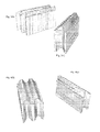
- the continuously curved surfaces of opposite faces are in phase with each other, such that two identical blocks may be placed side to side and “fit” together, and may likewise be stacked one on top of another and “fit together”. Figs. 1-4 illustrate such blocks.
- a block constructed vertical wall would have top and bottom surfaces in a continuous curve, and left and right surfaces in a continuous curve, while the front and rear surfaces would be substantially planar.
- the top and bottom surfaces would be the flat, substantially planar surfaces, while the front and back bair and the left and right pair would be the surfaces whose cross sections are continuously curved.
- the cross section of the curved surfaces is sine waves, as described above; the cross-sections have no flat portions.
- the blocks of the invention include sine waves of a variety of amplitudes (peak-to-peak).
- peak-to-peak amplitude it is meant the distance between the highest peak in the wave and the lowest trough in the wave.
- the amplitude of the cross sectional sine wave may be in a range from about 0.2 wavelengths to about 0.7 wavelengths.
- the amplitude is between about 0.2 wavelengths to about 0.5 wavelengths, more preferably, about 0.2 wavelengths to about 0.4 wavelengths.
- Wall construction generally proceeds with the building of course upon course until the desired height is reached.
- a wall is considered a single wythe wall.
- the thickness of such a single wythe wall may well be insufficient for both radiation shielding purposes as well as mechanical stability and rigidity of the wall itself.
- a second wythe may then be built abutting the first wythe in order to confer additional thickness to the end-resulting wall, advantageous both in terms of structural integrity and radiation shielding capacity. Additional wythes may be constructed to improve these characteristics even further.
- the invention is directed to a masonry block for constructing walls, the block having flat opposed front and rear surfaces, continuously curved opposed left and right surfaces, and continuously curved opposed top and bottom surfaces, and wherein the continuously curved surfaces are sinusoidal.
- the walls are radiation-protective, and the block has a density in the range between 2403 and 6407 kg/m 3 (150 pounds and 400 pounds per cubic foot), or between 3204 and 5606 kg/m 3 (200 and 350 pounds per cubic foot), or between 4005 and 5014 kg/m 3 (250 and 313 pounds per cubic foot).
- the sinusoidal continuously curved surfaces are two wavelengths long.
- the continuously curved surface are a sine wave in cross section, and in some aspects the amplitude of the sine wave is between about 0.2 and 0.7 wavelengths, or between about 0.2 and 0.4 wavelengths.
- the block may be of conventional size.
- the block is 25,4 cm (10 inches) in width, 12,7 cm (5 inches) in height, and 12,7 cm (5 inches) in depth.
- the invention provides a wall constructed with a plurality of blocks as previously described.
- a plurality of courses of a single wythe of the wall are offset laterally by one half the width of the blocks.
- the wall is a single staggered wythe as descrobed below, whose courses have been offset by one wavelength from adjacent courses.
- a plurality of half blocks may be placed in those courses offset and recessed from the exterior surfaces of the wall. Additionally, during construction, voids of appropriate dimension may be left in the wall for the insertion of reinforcement materials such as mortar, re-bar, I-beams, and other reinforcing materials, and combinations thereof.
- the present invention provides masonry blocks whose surfaces enable wall construction with interlocking blocks. This feature provides immobility and structural rigidity in multiple dimensions, and thereby provides superior wall building construction. Further, the present invention provides vastly superior radiation resistance because the surface profiles of the blocks are capable of mating and interlocking with adjacent blocks not only in multiple dimensions but also in a manner which minimizes seams through successive courses and wythes of a wall constructed with such blocks.
- the present invention provides interlocking building blocks capable of blocking radiation. While the blocks of the invention are suitable for general wall construction, the use of desireably dense materials render the blocks particularly useful for constructing walls capable of significantly blocking electromagnetic radiation, including but not limited to photon, gamma, and neutron radiation. Particularly, the blocks are molded into a shape conducive to interlocking with other adjacent blocks in two perpendicular directions. The profile of the blocks resembles a "tongue and groove" pattern, constructed of two identical and therefore complementary continuously curved sine wave surfaces, which abut one another and thereby fit together firmly.
- the blocks of the present invention are generally modified parallelopipeds, or more particularly modified rectangular cuboids, in that they have 6 faces or surfaces, opposing pairs of which are essentially parallel.
- essentially parallel it is meant that each point on the curved surface is the same distance from the equivalent point on the opposite, continuously curved, surface.
- all pairs of opposite points of the opposed curved surfaces are equidistant, and that distance is equal to the respective width, depth, or height of the block. They have front and rear surfaces, top and bottom surfaces, and left and right surfaces. At least two of the pairs of opposing surfaces are modified to be continuously curved surfaces, while the remaining pair of opposing surfaces (generally the front and back) may remain flat and generally planar.
- the front and rear surfaces are substantially flat, while the other four surfaces are not flat, but instead are continuously curved in cross section.
- the curved surfaces of the top, bottom, left and right are continuously curved such that there are no sharp angles on the surfaces, althought the corners may be angular.
- the continuously curved surfaces each are two complete wavelengths of a sine wave; that is, the block's thickness in either dimension is equal to two wavelengths of the cross-sectional sine curve.
- the continuously curved surfaces of opposite faces are in phase with each other, such that two identical blocks may be placed side to side and "fit” together, and may likewise be stacked one on top of another and “fit together”. Figs. 1-4 illustrate such blocks.
- the curved top surface is shaped to substantially conform to the respective bottom curved surface of the block to be placed on top of it.
- the side surfaces are shaped to substantially conform to the respective sides of adjacent blocks.
- the wavelength of the curve of the top and bottom surfaces is the same as that of the side surfaces.
- blocks may be placed directly abutting such that their front and rear faces are coplanar, or may be placed offset by one wavelength (i.e., half of a block) to form a staggered conformation. Additionally, whether placed directly abutting or offset by one half block, the blocks are self-aligning because they fit together in an interlocking fashion, both in vertical and horizontal dimensions. Moreover, structural rigidity and integrity is enhanced because the blocks, once placed, are immobilized from movement both vertically and laterally forward-rearward. Side-to-side freedom, however, is useful and advantageous as described below for staggered courses (side-to-side offset).
- the curved surfaces are sinusoidal, and in cross-section have no flat portions.
- the blocks of the invention may comprise sine waves of a variety of amplitudes. In one embodiment, the amplitude is that which is equal to one half the wavelength of the sine wave. In other embodiments, the amplitude of the cross sectional sine wave may be in a range from about 0.2 wavelengths to about 0.7 wavelengths. Preferably the amplitude is between about 0.2 wavelengths to about 0.5 wavelengths, more preferably, about 0.2 wavelengths to about 0.4 wavelengths.
- Blocks of the present invention may be formed to any convenient size suitable for wall construction.
- the dimensions of the full blocks of the invention may range, in any one dimension, from about 7,5 cm (3 inches) to about 40,6 cm (16 inches). In one embodiment, the width is twice the height and twice the depth, but in other embodiments, the ratios of the three dimensions vary.
- Conventional concrete blocks (often with large internal voids) range in size but are generally about 40,6 cm (16 inches) wide by 20,3 cm (8 inches) high by 20,3 cm (8 inches) deep.
- the present invention includes blocks of conventional size, but also includes blocks of other advantageous sizes.
- the size of the blocks may be adapted for suitability in general construction (where conventional sizes may be appropriate) or may be adapted to provide a suitable weight per block, particularly where conventional size blocks may have disadvantageous weight properties when the blocks' composition is high density material.
- the full size blocks of the invention are 25,4 cm (10 inches) wide by 12,7 cm (5 inches) high by 12,7 cm (5 inches) deep. Such a size combines advantageous weight properties for high density composition with sufficient size for many radiation facility wall construction specifications.
- Half blocks of the invention have the same dimensions as full blocks in two dimensions, while the third dimension (depth) is half that of a full block. In this fashion, half blocks may be advantageously used in staggered wythe wall construction. In one embodiment, half blocks are 25,4 cm (10 inches) wide by 12,7 cm (5 inches) high by 6,4 cm (2.5 inches) deep to match the dimensions of the full blocks of the same height and width, and the halved depth is thus one wavelength long.
- block configurations having some or all of the interlocking structures described above can be included in the block construction system.
- These other blocks include half-blocks as previously described, but also end blocks, corner blocks, bond beam blocks, tee blocks, crossing blocks and other specialty blocks.
- the different block configurations may be combined to construct walls of various shapes and sizes. See, for example, Fig. 6(c) , in which blocks turned on end are used to terminate one end of a three wythe wall. In such a case, the continuous curve of the end surfaces is the same as that of the top and bottom surfaces.
- Such blocks turned on end may also be used in a staggered wythe wall as described below.
- voids may be left during construction to establish vertically or horizontally aligned passageways in selected courses and wythes to accommodate reinforcement in the form of mortar, re-bar, I-beams, and other reinforcement materials.
- Courses of blocks set atop each other may be staggered for further strengthening of the resulting wall. Due to the top and bottom surfaces of the blocks mating shapes, a block may be placed on top of a lower course with its sides aligning directly with the seam between blocks in the lower course, or may be staggered left and right by any amount. In this way the seams between blocks in each successive course may overlap the seams of the course below.
- each successive course is offset side-to-side by half the width of a block, such that the seam between blocks of such course falls directly above the center of the block below it. In other embodiments, the offset ranges from zero to half the block width.
- Staggered course construction may also be combined with staggered wythe wall construction as described below.
- the blocks of the invention are amenable to the rapid construction of walls by masons, due to their unique curved features which provide for automatic alignment. Additionally, the blocks of the invention are particularly suitable for automated construction of walls by robotic machinery, which can lift and place many blocks in a single operation. Smaller robotic devices may lay as few as two or three blocks at a time, while larger devices may be able to place dozens of blocks simultaneously.
- the blocks of the present invention enable wall construction with staggered wythes, whereby a successive course of blocks is set atop a previous course, offset by one wavelength in a front-rear direction by half the thickness of the block.
- the top faces of the blocks of multiple wythes match in surface shape, the bottom face of a successive course will fit snugly even while overlapping two blocks in previously laid abutting courses.
- the second course for both wythes may be a single course overlapping both previously laid courses, thereby overlapping both wythes.
- two such overlapping blocks may be placed on the three courses below.
- half blocks may be used to "fill" the gaps in the overlapping courses, rendering a final wall having a single thickness throughout its height, without individual independent wythes abutting each other. Instead, the thickness is the result of the interlocking staggering nature of the construction.
- Staggered wythe construction inherently provides additional strength to the resulting wall, due at least in part to the ability to spread the load of successive courses on a greater base area, as opposed to each course applying its load solely on the course beneath. Additionally, staggered wythe construction also avoids the expense and labor of tying unstaggered wythes together with additional mechanisms, such as ties, leashes, and the like.
- block configurations having some or all of the interlocking structures described above may be included in a block construction system. These other blocks include half-blocks, end blocks, corner blocks, bond beam blocks, tee blocks, crossing blocks and other specialty blocks. These different block configurations can be combined to construct walls of various shapes and sizes.
- half blocks comprising surfaces of length or width equal to one wavelength may be used to bring those courses which have been offset by one wavelength to the same depth as the other courses in the wythe.
- that offset course may have half blocks added to and abutting their front faces in order to render the wythe with a continous smooth surface.
- voids may be left during construction to establish vertically or horizontally aligned passageways in selected courses, wythes, and staggered wythe walls.
- Radiation protection requires the interposition of high density material between the source and the outside environment.
- the source In facilities which use radiation, the source is generally housed in a machine in a shielded room. At least the walls and ceiling of the room, and in some cases the floor, must be appropriately shielded by sufficient thickness walls to prevent radiation from leaking out.
- Traditional wall construction even with high density materials which are efficient at radiation blocking, is prone to seams between blocks that ultimately require additional wythes of walls to reach thicknesses capable of blocking radiation through the seams.
- the present invention prevents seams capable of passing radiation, and thereby permits construction of a wall using the same high density materials but with fewer wythes, or a staggered wythe wall of reduced thickness. Additionally, because there is little to no need to mortar between blocks, courses, and wythes, both the cost and the length of time for building the walls are substantially diminished.
- While blocks have been described in the art which reduce seams, none have essentially eliminated seams as in the present invention.
- a triangular profile block for example, is able to reduce the seam, such blocks have been made with substantially horizontal portions in the profile of the surface of the block, thereby maintaining an open seam through which radiation may pass.
- such blocks still permit a substantial portion of radiation (as much as one third to one half) to leak through the block seams because less material is interposed between the inside and outside of the wall.
- Walls constructed from such blocks need at least 50% more wythes to block the same percentage of radiation as walls constructed of blocks of the present invention.
- blocks of the invention destined for use in radiation shielding have composition densities of between 3204 and 6407 kg/m 3 (200 and 400 pounds per cubic foot), preferably 3524 and 6007 kg/m 3 (220 to 375 pounds per cubic foot), more preferably between 3684 and 5446 kg/m 3 (230 to 340 pounds per cubic foot).
- blocks of the invention have a density of 4005 kg/m 3 (250 pounds per cubic foot).
- blocks of the invention have a density of 5014 kg/m 3 (313 pounds per cubic foot).
- Walls constructed as described provide excellent radiation shielding, with essentially no seams through which radiation is permitted to leak.
- the wall of the invention provides the same radiation protection of a conventional wall of much greater thickness, as high as twice the thickness or even greater.
- High-density concrete blocks of the invention can be produced in a variety of dimensions.
- Blocks were foremed with the following dimensions: 12,7 cm (5 inches) square on end (height and depth) and 25,4 cm (10 inches) wide.
- the top and bottom surfaces have a cross-sectional continuous curve in the shape of a sine wave with the sine wave wavelength being one-half the width of the block, or 6,35 cm (2.5 inches).
- the sine wave amplitude is independent of the dimensions of the block and can be selected based upon structural needs.
- the amplitude (peak-to-peak) is 1,9 cm (0.75 inches), that is, 0.3 times the wavelength.
- This block's left and right side are also continuously curved in a sinusoidal curve of the same wavelength, 6,3 cm (2.5 inches).
- the sine-wave profile on the bottom of the block is in phase with the respective wave on the top of the blocks, such that blocks interlock directly on top of one another.
- a similar pair of in-phase sine wave profiles are present on the sides of the block, to provide interlocking functionality in the lateral side-to-side direction.
- This sine-wave profile allows subsequent block layers to be offset by one wave-length in a staggered wythe wall construction. This prevents wall wythes from separating from each other, effectively allowing the blocks themselves to hold the wall together.
- Subfigures (b) of Figs. 1-4 depict a full size block as contemplated by this Example, with one opposed pair of substantially planar surfaces and two pairs of surfaces featuring two wavelengths of regular sine curved cross-sections.
- Subfigures (a) of Figs. 1-4 depict a half block with matching curved surfaces but only a single wavelength thereof.
- the blocks were composed of highly dense material, with a density of either 4005 or 5014 kg/m 3 (250 or 313 pounds per cubic foot).
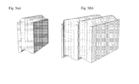
- Example 5(b) The full size blocks of this Example bear surfaces whose cross-sections are two wavelengths of a distorted sine curve, as illustrated in Example 5(b). In all other respects, these blocks are essentially similar to those of Example 1, but for the shape profile of their respective curved surfaces.
- Fig. 5(a) depicts a half block bearing a single wavelength of continuously distorted sine curve.
- a staggered wythe wall construction uses full and half blocks of Example 1.
- the lower right side and the upper left (unseen) side are the exterior surfaces of the wall
- the left side and the right (unseen) side are the exterior surfaces of the wall.
- Walls constructed as described provide excellent radiation shielding, with essentially no seams through which radiation is permitted to leak.
- the wall of the invention provides the same radiation protection of a conventional wall of twice the thickness (i.e., twice the number of wythes).
Landscapes
- Engineering & Computer Science (AREA)
- Architecture (AREA)
- Physics & Mathematics (AREA)
- General Engineering & Computer Science (AREA)
- High Energy & Nuclear Physics (AREA)
- Civil Engineering (AREA)
- Structural Engineering (AREA)
- Electromagnetism (AREA)
- Finishing Walls (AREA)
- Revetment (AREA)
Claims (11)
- Bloc de maçonnerie à blindage contre les rayonnements pour construire des murs capables de bloquer les rayonnements, incluant mais sans s'y limiter les rayonnements de photons, gamma et de neutrons, le bloc présentant des surfaces avant et arrière planaires opposées définissant une épaisseur du bloc, des surfaces gauche et droite opposées incurvées en continu, et des surfaces supérieure et inférieure opposées incurvées en continu, caractérisé en ce que
les surfaces incurvées en continu présentent un modèle d'ondulation sinusoïdale régulier ayant une direction d'ondulation perpendiculaire aux surfaces avant et arrière planaires opposées, et en ce que
chacune des surfaces incurvées en continu fait deux longueurs complètes d'ondulations et s'étend dans la direction d'ondulation sur toute l'épaisseur du bloc. - Bloc selon la revendication 1, dans lequel le bloc présente une densité située dans la plage entre 2403 et 6407 kg/m3 (150 livres et 400 livres par pied cube).
- Bloc selon la revendication 2, dans lequel la densité est située dans la plage entre 3204 et 5606 kg/m3 (200 livres et 350 livres par pied cube).
- Bloc selon la revendication 3, dans lequel la densité est située dans la plage entre 4005 et 5014 kg/m3 (250 livres et 313 livres par pied cube).
- Bloc selon la revendication 1, dans lequel une amplitude de l'ondulation sinusoïdale est située entre 0,2 et 0,7 longueurs d'ondulations.
- Bloc selon la revendication 1, dans lequel une amplitude de l'ondulation sinusoïdale est située entre 0,2 et 0,4 longueurs d'ondulations.
- Bloc selon la revendication 6, dans lequel le bloc à une largeur de 25,4 cm (10 pouces), une hauteur de 12,7 cm (5 pouces) et une profondeur de 12,7 cm (5 pouces).
- Mur construit avec une pluralité de blocs selon la revendication 1, dans lequel le mur est construit avec une pluralité de rangs de blocs et une pluralité de parois agencées dans une construction de parois décalées, ce par quoi un rang successif de blocs placés au-dessus d'un rang précédent est décalé d'une longueur d'ondulation du rang précédent dans une direction avant-arrière.
- Mur selon la revendication 8, dans lequel le rang successif de blocs est décalé latéralement d'une moitié de la largeur des blocs du rang précédent.
- Mur selon la revendication 8, comprenant en outre une pluralité de mi-blocs placés dans les rangs décalés et en retrait des surfaces extérieures du mur.
- Mur selon la revendication 8, comprenant en outre des vides pour l'insertion de matériaux de renfort sélectionnés parmi le groupe consistant en :mortier, barre pour béton armé, poutres en I et des combinaisons de ceux-ci.
Priority Applications (1)
| Application Number | Priority Date | Filing Date | Title |
|---|---|---|---|
| PL09808923T PL2319048T3 (pl) | 2008-08-22 | 2009-08-24 | Blok murarski z powierzchniami zakrzywionymi w sposób ciągły |
Applications Claiming Priority (2)
| Application Number | Priority Date | Filing Date | Title |
|---|---|---|---|
| US9097808P | 2008-08-22 | 2008-08-22 | |
| PCT/US2009/054814 WO2010022406A1 (fr) | 2008-08-22 | 2009-08-24 | Bloc de construction avec surfaces incurvées en continu |
Publications (3)
| Publication Number | Publication Date |
|---|---|
| EP2319048A1 EP2319048A1 (fr) | 2011-05-11 |
| EP2319048A4 EP2319048A4 (fr) | 2012-04-25 |
| EP2319048B1 true EP2319048B1 (fr) | 2015-08-12 |
Family
ID=41707492
Family Applications (1)
| Application Number | Title | Priority Date | Filing Date |
|---|---|---|---|
| EP09808923.8A Active EP2319048B1 (fr) | 2008-08-22 | 2009-08-24 | Bloc de construction avec surfaces incurvées en continu |
Country Status (6)
| Country | Link |
|---|---|
| US (2) | US9183957B2 (fr) |
| EP (1) | EP2319048B1 (fr) |
| ES (1) | ES2552800T3 (fr) |
| PL (1) | PL2319048T3 (fr) |
| PT (1) | PT2319048E (fr) |
| WO (1) | WO2010022406A1 (fr) |
Families Citing this family (18)
| Publication number | Priority date | Publication date | Assignee | Title |
|---|---|---|---|---|
| CA2605426C (fr) * | 2005-04-18 | 2016-02-09 | Q-Ba-Maze Inc. | Interconnexion d'appareil a voie modulaire |
| EP2572360A4 (fr) * | 2010-05-18 | 2015-12-16 | Veritas Medical Solutions Llc | Installation à particules modulaire compacte ayant des barrières à couches |
| US8820024B1 (en) * | 2013-03-11 | 2014-09-02 | Mohammad A. H. S. H. Abdullah | Wall building system and method |
| CA2906897C (fr) * | 2013-03-15 | 2019-04-02 | Abt, Inc. | Ensemble de forme a verrouillage mutuel |
| US9458661B2 (en) * | 2013-03-15 | 2016-10-04 | Veritas Medical Solutions Llc | Sliding door with tortuous leading edge path |
| US9702138B1 (en) * | 2013-05-17 | 2017-07-11 | Modula S, Inc. | Modular building construction |
| CN106032729A (zh) * | 2015-03-17 | 2016-10-19 | 瓦里安医疗器械贸易(北京)有限公司 | 预制的模块化放射治疗拱顶室设计 |
| US9809971B2 (en) * | 2016-02-25 | 2017-11-07 | Spherical Block LLC | Architectural building block |
| US20180061875A1 (en) * | 2016-08-30 | 2018-03-01 | Stmicroelectronics (Crolles 2) Sas | Vertical transfer gate transistor and active cmos image sensor pixel including a vertical transfer gate transistor |
| US20230030089A1 (en) * | 2016-10-26 | 2023-02-02 | Innovative Design Solutions Llc | Modular Precast Concrete Water Storage Device and System |
| KR101861837B1 (ko) * | 2017-12-29 | 2018-05-28 | 박재홍 | 쐐기형 결합부가 형성된 블록과 프레임을 이용한 벽체 구조 및 이를 이용한 벽체 시공방법 |
| US11066827B2 (en) | 2018-03-15 | 2021-07-20 | Daysh Developments, Inc. | Precision dry-stack masonry unit |
| BR202018011162U2 (pt) * | 2018-05-30 | 2019-12-03 | Cesar Augusto Marcos | disposição aplicada em bloco de encaixe |
| JP6656442B1 (ja) * | 2019-02-15 | 2020-03-04 | 株式会社安藤・間 | 遮蔽体、及び放射化抑制構造 |
| US10494810B1 (en) | 2019-03-12 | 2019-12-03 | Samuel Garunts | Mortarless building blocks wall |
| US10792512B1 (en) * | 2019-03-29 | 2020-10-06 | Pedro Kahn Machado DE SOUZA | Metallic modules and assembly system for the formation of shielded walls, floor and ceiling for rooms used for radiotherapy |
| US11638884B1 (en) * | 2021-10-28 | 2023-05-02 | Zhejiang Benlai Household Technology Co., Ltd. | Basic connecting block and connecting block group |
| US20240149184A1 (en) * | 2022-05-19 | 2024-05-09 | Full Sun LLC | Toy construction kits and related methods |
Citations (2)
| Publication number | Priority date | Publication date | Assignee | Title |
|---|---|---|---|---|
| US2970218A (en) * | 1958-10-29 | 1961-01-31 | American Smelting Refining | Brick for radiation shields |
| US6606835B1 (en) * | 2001-02-02 | 2003-08-19 | Augustin J. Bilka | Blocks and walls constructed therewith |
Family Cites Families (35)
| Publication number | Priority date | Publication date | Assignee | Title |
|---|---|---|---|---|
| US2462289A (en) * | 1945-06-11 | 1949-02-22 | Harbison Walker Refractories | Furnace refractory construction |
| US2932745A (en) * | 1956-06-07 | 1960-04-12 | Alberti Rudolf | Standard radiation-resistant building block |
| US3416276A (en) * | 1966-08-26 | 1968-12-17 | Intercon Res Inc | Masonry walls and partitions and method of fabricating same |
| CH436638A (fr) * | 1966-10-11 | 1967-05-31 | Leuthold Charles | Brique de protection contre les rayonnements radio-actifs |
| US3635459A (en) * | 1968-02-29 | 1972-01-18 | Arrigo Mare | Refractory brick having oblique surface |
| DE2345568A1 (de) * | 1973-09-10 | 1975-04-17 | Franz Julius Dipl Ing Gergely | Bau-elemente |
| US4101255A (en) * | 1974-08-23 | 1978-07-18 | Fernaeus S E | Apparatus for manufacturing wave-shape building blocks |
| GB1533980A (en) * | 1975-02-20 | 1978-11-29 | Redland Technology Ltd | Building blocks |
| US4107894A (en) * | 1976-10-29 | 1978-08-22 | Mullins Wayne L | Interlocking cementitious building blocks |
| FR2398142A1 (fr) * | 1977-07-18 | 1979-02-16 | Guenin Jacques | Paves en beton autobloquants pour revetement des sols |
| US4437013A (en) * | 1981-07-06 | 1984-03-13 | The United States Of America As Represented By The Department Of Energy | Neutron and gamma radiation shielding material, structure, and process of making structure |
| US4512685A (en) * | 1981-09-08 | 1985-04-23 | Ameron, Inc. | Mortarless retaining-wall system and components thereof |
| BR8208077A (pt) * | 1981-11-12 | 1984-04-17 | Frank Stratton | Bloco de construcao ou painel aperfeicoado |
| US4787185A (en) * | 1982-02-11 | 1988-11-29 | Dwayne Gascho | Log structures and method of constructing same |
| US4414339A (en) * | 1982-03-15 | 1983-11-08 | The Dow Chemical Company | Low density, electromagnetic radiation absorption composition |
| DE3505530A1 (de) * | 1985-02-18 | 1986-08-21 | Sf-Vollverbundstein-Kooperation Gmbh, 2820 Bremen | (beton-) formstein fuer stuetzmauern sowie stuetzmauer |
| GB2185512B (en) * | 1986-01-21 | 1989-11-01 | Mccauley Corp Ltd | Retaining wall system |
| US4773790A (en) * | 1986-06-04 | 1988-09-27 | Gerhard Hagenah | Groundcovering element, especially (concrete) slab |
| US4973192A (en) * | 1990-03-22 | 1990-11-27 | Hair Roberta A | Interlocking paving stone and ground cover formed thereof |
| US5178921A (en) * | 1991-09-03 | 1993-01-12 | Inland Steel Company | Burner block assembly and material |
| US5428934A (en) * | 1993-11-26 | 1995-07-04 | Tomek; Debby E. | Interlocking slab elements |
| GB9407485D0 (en) | 1994-04-15 | 1994-06-08 | U P S Ltd | Improvements in and relating to surfacing blocks |
| US5633508A (en) * | 1995-10-12 | 1997-05-27 | Cold Spring Granite Company | Secondary shielding structure |
| USD377397S (en) * | 1995-11-16 | 1997-01-14 | Craig Carl E | Cinder block |
| US6286251B1 (en) * | 1996-04-10 | 2001-09-11 | Bend Industries, Inc. | Interlocking composite masonry edging or stepping block |
| NL1003138C2 (nl) * | 1996-05-15 | 1997-11-18 | Den Boer Beton Groot Ammers B | Bekleding voor een oever. |
| US6871468B2 (en) * | 2000-08-28 | 2005-03-29 | Bend Industries, Inc. | Interlocking masonry wall block |
| US7305803B2 (en) * | 2000-09-18 | 2007-12-11 | Daniel Correa | Block construction system |
| USD457656S1 (en) * | 2001-02-02 | 2002-05-21 | Augustin J. Bilka | Brick block |
| US6854231B2 (en) * | 2001-07-12 | 2005-02-15 | Keystone Retaining Wall Systems, Inc. | Multi-channel retaining wall block and system |
| US7040241B2 (en) * | 2002-05-24 | 2006-05-09 | Merkle Engineers, Inc. | Refractory brick and refractory construction |
| US6948282B2 (en) * | 2003-01-09 | 2005-09-27 | Allan Block Corporation | Interlocking building block |
| USD481136S1 (en) * | 2003-02-21 | 2003-10-21 | Innovative Concrete Solutions, Inc. | Curved wall block |
| US7185470B1 (en) * | 2004-03-31 | 2007-03-06 | E. Dillon & Company | Retaining wall block |
| US7037047B1 (en) * | 2004-12-02 | 2006-05-02 | Anchor Wall Systems, Inc. | Retaining wall block system |
-
2009
- 2009-08-24 EP EP09808923.8A patent/EP2319048B1/fr active Active
- 2009-08-24 ES ES09808923.8T patent/ES2552800T3/es active Active
- 2009-08-24 PL PL09808923T patent/PL2319048T3/pl unknown
- 2009-08-24 PT PT98089238T patent/PT2319048E/pt unknown
- 2009-08-24 WO PCT/US2009/054814 patent/WO2010022406A1/fr not_active Ceased
- 2009-08-24 US US13/060,157 patent/US9183957B2/en active Active
-
2015
- 2015-08-24 US US14/833,696 patent/US9816267B2/en active Active
Patent Citations (2)
| Publication number | Priority date | Publication date | Assignee | Title |
|---|---|---|---|---|
| US2970218A (en) * | 1958-10-29 | 1961-01-31 | American Smelting Refining | Brick for radiation shields |
| US6606835B1 (en) * | 2001-02-02 | 2003-08-19 | Augustin J. Bilka | Blocks and walls constructed therewith |
Non-Patent Citations (2)
| Title |
|---|
| ANONYMOUS: "High Density Concrete Block", 20 May 2007 (2007-05-20), XP055104271, Retrieved from the Internet <URL:https://web.archive.org/web/20070520094642/http://www.jzimaging.com/Nelco_high_density_block.htm> [retrieved on 20140225] * |
| ANONYMOUS: "Standard Lead Brick & Interlocking Lead Brick", 17 June 2008 (2008-06-17), XP055104246, Retrieved from the Internet <URL:https://web.archive.org/web/20080617012243/http://www.radiationproducts.com/bricks.htm> [retrieved on 20140225] * |
Also Published As
| Publication number | Publication date |
|---|---|
| EP2319048A4 (fr) | 2012-04-25 |
| EP2319048A1 (fr) | 2011-05-11 |
| PL2319048T3 (pl) | 2016-02-29 |
| ES2552800T3 (es) | 2015-12-02 |
| US20160024784A1 (en) | 2016-01-28 |
| US20110146191A1 (en) | 2011-06-23 |
| US9816267B2 (en) | 2017-11-14 |
| PT2319048E (pt) | 2015-11-25 |
| US9183957B2 (en) | 2015-11-10 |
| WO2010022406A1 (fr) | 2010-02-25 |
Similar Documents
| Publication | Publication Date | Title |
|---|---|---|
| US9183957B2 (en) | Masonry block with continuously curved surfaces | |
| US10760281B2 (en) | Veneer connectors, wall blocks, veneer panels for wall blocks, and walls | |
| US7959380B2 (en) | Landscaping system | |
| US8171693B2 (en) | Interlocking masonry blocks | |
| CA2900396A1 (fr) | Dalle de patio, systeme de patio et procede de fabrication de patio | |
| RU2304672C2 (ru) | Строительная панель и способ сооружения | |
| Kintingu | Design of interlocking bricks for enhanced wall construction, flexibility, alignment accuracy and load bearing | |
| KR20250065580A (ko) | 입체결합 옹벽 블록시스템 | |
| US4703599A (en) | Concrete masonry footer block foundation system and blocks therefor | |
| US20210054623A1 (en) | Cementitious building block with interconnecting features | |
| JP2015101937A (ja) | 杭式液状化対策構造体およびその構築方法 | |
| GB2283996A (en) | Dry stone wall block | |
| WO2011111002A1 (fr) | Bloc de construction et procédé permettant de monter des murs à l'aide d'un tel bloc | |
| AU2012206266B2 (en) | Reversible, thermo-acoustic panel for reversible, variable-geometry formwork | |
| JP3729415B2 (ja) | 建設物基礎構造 | |
| CN112922379A (zh) | 一种建筑加固方法 | |
| CN107217684A (zh) | 挡墙砌筑方法及应用其砌筑的挡墙 | |
| RU59650U1 (ru) | Сейсмостойкое малоэтажное здание, сооружение | |
| CA2627851C (fr) | Systeme pour amenagement paysager | |
| KR100654198B1 (ko) | 건축물의 기초 구조 | |
| GB2385071A (en) | Building foundation with insulating members | |
| EP1335073A2 (fr) | Fondations | |
| CN109322504B (zh) | 一种既有砖石箍窑窑脸加固方法 | |
| SU1285123A1 (ru) | Стена из природных камней | |
| AU677131B2 (en) | Concrete building block |
Legal Events
| Date | Code | Title | Description |
|---|---|---|---|
| PUAI | Public reference made under article 153(3) epc to a published international application that has entered the european phase |
Free format text: ORIGINAL CODE: 0009012 |
|
| 17P | Request for examination filed |
Effective date: 20110222 |
|
| AK | Designated contracting states |
Kind code of ref document: A1 Designated state(s): AT BE BG CH CY CZ DE DK EE ES FI FR GB GR HR HU IE IS IT LI LT LU LV MC MK MT NL NO PL PT RO SE SI SK SM TR |
|
| AX | Request for extension of the european patent |
Extension state: AL BA RS |
|
| DAX | Request for extension of the european patent (deleted) | ||
| A4 | Supplementary search report drawn up and despatched |
Effective date: 20120322 |
|
| RIC1 | Information provided on ipc code assigned before grant |
Ipc: G21F 3/00 20060101ALI20120316BHEP Ipc: E04B 2/02 20060101ALN20120316BHEP Ipc: G21F 1/04 20060101AFI20120316BHEP |
|
| 17Q | First examination report despatched |
Effective date: 20130125 |
|
| REG | Reference to a national code |
Ref country code: DE Ref legal event code: R079 Ref document number: 602009032905 Country of ref document: DE Free format text: PREVIOUS MAIN CLASS: G21C0011000000 Ipc: G21F0001040000 |
|
| GRAP | Despatch of communication of intention to grant a patent |
Free format text: ORIGINAL CODE: EPIDOSNIGR1 |
|
| RIC1 | Information provided on ipc code assigned before grant |
Ipc: E04B 2/02 20060101ALN20150302BHEP Ipc: G21F 1/04 20060101AFI20150302BHEP Ipc: G21F 3/00 20060101ALI20150302BHEP |
|
| INTG | Intention to grant announced |
Effective date: 20150326 |
|
| GRAS | Grant fee paid |
Free format text: ORIGINAL CODE: EPIDOSNIGR3 |
|
| GRAA | (expected) grant |
Free format text: ORIGINAL CODE: 0009210 |
|
| AK | Designated contracting states |
Kind code of ref document: B1 Designated state(s): AT BE BG CH CY CZ DE DK EE ES FI FR GB GR HR HU IE IS IT LI LT LU LV MC MK MT NL NO PL PT RO SE SI SK SM TR |
|
| REG | Reference to a national code |
Ref country code: GB Ref legal event code: FG4D |
|
| REG | Reference to a national code |
Ref country code: CH Ref legal event code: EP |
|
| REG | Reference to a national code |
Ref country code: AT Ref legal event code: REF Ref document number: 742771 Country of ref document: AT Kind code of ref document: T Effective date: 20150815 |
|
| REG | Reference to a national code |
Ref country code: IE Ref legal event code: FG4D |
|
| REG | Reference to a national code |
Ref country code: DE Ref legal event code: R096 Ref document number: 602009032905 Country of ref document: DE |
|
| REG | Reference to a national code |
Ref country code: PT Ref legal event code: SC4A Free format text: AVAILABILITY OF NATIONAL TRANSLATION Effective date: 20151111 |
|
| REG | Reference to a national code |
Ref country code: ES Ref legal event code: FG2A Ref document number: 2552800 Country of ref document: ES Kind code of ref document: T3 Effective date: 20151202 |
|
| REG | Reference to a national code |
Ref country code: LT Ref legal event code: MG4D |
|
| REG | Reference to a national code |
Ref country code: AT Ref legal event code: MK05 Ref document number: 742771 Country of ref document: AT Kind code of ref document: T Effective date: 20150812 |
|
| REG | Reference to a national code |
Ref country code: NL Ref legal event code: MP Effective date: 20150812 |
|
| PG25 | Lapsed in a contracting state [announced via postgrant information from national office to epo] |
Ref country code: LT Free format text: LAPSE BECAUSE OF FAILURE TO SUBMIT A TRANSLATION OF THE DESCRIPTION OR TO PAY THE FEE WITHIN THE PRESCRIBED TIME-LIMIT Effective date: 20150812 Ref country code: FI Free format text: LAPSE BECAUSE OF FAILURE TO SUBMIT A TRANSLATION OF THE DESCRIPTION OR TO PAY THE FEE WITHIN THE PRESCRIBED TIME-LIMIT Effective date: 20150812 Ref country code: GR Free format text: LAPSE BECAUSE OF FAILURE TO SUBMIT A TRANSLATION OF THE DESCRIPTION OR TO PAY THE FEE WITHIN THE PRESCRIBED TIME-LIMIT Effective date: 20151113 Ref country code: LV Free format text: LAPSE BECAUSE OF FAILURE TO SUBMIT A TRANSLATION OF THE DESCRIPTION OR TO PAY THE FEE WITHIN THE PRESCRIBED TIME-LIMIT Effective date: 20150812 Ref country code: NO Free format text: LAPSE BECAUSE OF FAILURE TO SUBMIT A TRANSLATION OF THE DESCRIPTION OR TO PAY THE FEE WITHIN THE PRESCRIBED TIME-LIMIT Effective date: 20151112 |
|
| PG25 | Lapsed in a contracting state [announced via postgrant information from national office to epo] |
Ref country code: IS Free format text: LAPSE BECAUSE OF FAILURE TO SUBMIT A TRANSLATION OF THE DESCRIPTION OR TO PAY THE FEE WITHIN THE PRESCRIBED TIME-LIMIT Effective date: 20151212 Ref country code: SE Free format text: LAPSE BECAUSE OF FAILURE TO SUBMIT A TRANSLATION OF THE DESCRIPTION OR TO PAY THE FEE WITHIN THE PRESCRIBED TIME-LIMIT Effective date: 20150812 Ref country code: HR Free format text: LAPSE BECAUSE OF FAILURE TO SUBMIT A TRANSLATION OF THE DESCRIPTION OR TO PAY THE FEE WITHIN THE PRESCRIBED TIME-LIMIT Effective date: 20150812 Ref country code: AT Free format text: LAPSE BECAUSE OF FAILURE TO SUBMIT A TRANSLATION OF THE DESCRIPTION OR TO PAY THE FEE WITHIN THE PRESCRIBED TIME-LIMIT Effective date: 20150812 |
|
| PG25 | Lapsed in a contracting state [announced via postgrant information from national office to epo] |
Ref country code: NL Free format text: LAPSE BECAUSE OF FAILURE TO SUBMIT A TRANSLATION OF THE DESCRIPTION OR TO PAY THE FEE WITHIN THE PRESCRIBED TIME-LIMIT Effective date: 20150812 |
|
| REG | Reference to a national code |
Ref country code: CH Ref legal event code: PL |
|
| PG25 | Lapsed in a contracting state [announced via postgrant information from national office to epo] |
Ref country code: CZ Free format text: LAPSE BECAUSE OF FAILURE TO SUBMIT A TRANSLATION OF THE DESCRIPTION OR TO PAY THE FEE WITHIN THE PRESCRIBED TIME-LIMIT Effective date: 20150812 Ref country code: SK Free format text: LAPSE BECAUSE OF FAILURE TO SUBMIT A TRANSLATION OF THE DESCRIPTION OR TO PAY THE FEE WITHIN THE PRESCRIBED TIME-LIMIT Effective date: 20150812 Ref country code: EE Free format text: LAPSE BECAUSE OF FAILURE TO SUBMIT A TRANSLATION OF THE DESCRIPTION OR TO PAY THE FEE WITHIN THE PRESCRIBED TIME-LIMIT Effective date: 20150812 Ref country code: IT Free format text: LAPSE BECAUSE OF FAILURE TO SUBMIT A TRANSLATION OF THE DESCRIPTION OR TO PAY THE FEE WITHIN THE PRESCRIBED TIME-LIMIT Effective date: 20150812 Ref country code: LI Free format text: LAPSE BECAUSE OF NON-PAYMENT OF DUE FEES Effective date: 20150831 Ref country code: DK Free format text: LAPSE BECAUSE OF FAILURE TO SUBMIT A TRANSLATION OF THE DESCRIPTION OR TO PAY THE FEE WITHIN THE PRESCRIBED TIME-LIMIT Effective date: 20150812 Ref country code: CH Free format text: LAPSE BECAUSE OF NON-PAYMENT OF DUE FEES Effective date: 20150831 |
|
| REG | Reference to a national code |
Ref country code: DE Ref legal event code: R097 Ref document number: 602009032905 Country of ref document: DE |
|
| PG25 | Lapsed in a contracting state [announced via postgrant information from national office to epo] |
Ref country code: RO Free format text: LAPSE BECAUSE OF FAILURE TO SUBMIT A TRANSLATION OF THE DESCRIPTION OR TO PAY THE FEE WITHIN THE PRESCRIBED TIME-LIMIT Effective date: 20150812 Ref country code: MC Free format text: LAPSE BECAUSE OF FAILURE TO SUBMIT A TRANSLATION OF THE DESCRIPTION OR TO PAY THE FEE WITHIN THE PRESCRIBED TIME-LIMIT Effective date: 20150812 |
|
| REG | Reference to a national code |
Ref country code: IE Ref legal event code: MM4A |
|
| PLBE | No opposition filed within time limit |
Free format text: ORIGINAL CODE: 0009261 |
|
| STAA | Information on the status of an ep patent application or granted ep patent |
Free format text: STATUS: NO OPPOSITION FILED WITHIN TIME LIMIT |
|
| 26N | No opposition filed |
Effective date: 20160513 |
|
| PG25 | Lapsed in a contracting state [announced via postgrant information from national office to epo] |
Ref country code: IE Free format text: LAPSE BECAUSE OF NON-PAYMENT OF DUE FEES Effective date: 20150824 |
|
| PG25 | Lapsed in a contracting state [announced via postgrant information from national office to epo] |
Ref country code: SI Free format text: LAPSE BECAUSE OF FAILURE TO SUBMIT A TRANSLATION OF THE DESCRIPTION OR TO PAY THE FEE WITHIN THE PRESCRIBED TIME-LIMIT Effective date: 20150812 |
|
| REG | Reference to a national code |
Ref country code: FR Ref legal event code: ST Effective date: 20160902 |
|
| PG25 | Lapsed in a contracting state [announced via postgrant information from national office to epo] |
Ref country code: FR Free format text: LAPSE BECAUSE OF NON-PAYMENT OF DUE FEES Effective date: 20151012 |
|
| PG25 | Lapsed in a contracting state [announced via postgrant information from national office to epo] |
Ref country code: MT Free format text: LAPSE BECAUSE OF FAILURE TO SUBMIT A TRANSLATION OF THE DESCRIPTION OR TO PAY THE FEE WITHIN THE PRESCRIBED TIME-LIMIT Effective date: 20150812 |
|
| PG25 | Lapsed in a contracting state [announced via postgrant information from national office to epo] |
Ref country code: HU Free format text: LAPSE BECAUSE OF FAILURE TO SUBMIT A TRANSLATION OF THE DESCRIPTION OR TO PAY THE FEE WITHIN THE PRESCRIBED TIME-LIMIT; INVALID AB INITIO Effective date: 20090824 Ref country code: SM Free format text: LAPSE BECAUSE OF FAILURE TO SUBMIT A TRANSLATION OF THE DESCRIPTION OR TO PAY THE FEE WITHIN THE PRESCRIBED TIME-LIMIT Effective date: 20150812 Ref country code: BG Free format text: LAPSE BECAUSE OF FAILURE TO SUBMIT A TRANSLATION OF THE DESCRIPTION OR TO PAY THE FEE WITHIN THE PRESCRIBED TIME-LIMIT Effective date: 20150812 |
|
| PG25 | Lapsed in a contracting state [announced via postgrant information from national office to epo] |
Ref country code: CY Free format text: LAPSE BECAUSE OF FAILURE TO SUBMIT A TRANSLATION OF THE DESCRIPTION OR TO PAY THE FEE WITHIN THE PRESCRIBED TIME-LIMIT Effective date: 20150812 |
|
| PG25 | Lapsed in a contracting state [announced via postgrant information from national office to epo] |
Ref country code: BE Free format text: LAPSE BECAUSE OF NON-PAYMENT OF DUE FEES Effective date: 20150831 |
|
| PG25 | Lapsed in a contracting state [announced via postgrant information from national office to epo] |
Ref country code: TR Free format text: LAPSE BECAUSE OF FAILURE TO SUBMIT A TRANSLATION OF THE DESCRIPTION OR TO PAY THE FEE WITHIN THE PRESCRIBED TIME-LIMIT Effective date: 20150812 |
|
| PG25 | Lapsed in a contracting state [announced via postgrant information from national office to epo] |
Ref country code: LU Free format text: LAPSE BECAUSE OF NON-PAYMENT OF DUE FEES Effective date: 20150824 |
|
| PG25 | Lapsed in a contracting state [announced via postgrant information from national office to epo] |
Ref country code: MK Free format text: LAPSE BECAUSE OF FAILURE TO SUBMIT A TRANSLATION OF THE DESCRIPTION OR TO PAY THE FEE WITHIN THE PRESCRIBED TIME-LIMIT Effective date: 20150812 |
|
| PGFP | Annual fee paid to national office [announced via postgrant information from national office to epo] |
Ref country code: ES Payment date: 20250929 Year of fee payment: 17 Ref country code: PT Payment date: 20250908 Year of fee payment: 17 |
|
| PGFP | Annual fee paid to national office [announced via postgrant information from national office to epo] |
Ref country code: DE Payment date: 20250902 Year of fee payment: 17 |
|
| PGFP | Annual fee paid to national office [announced via postgrant information from national office to epo] |
Ref country code: PL Payment date: 20250912 Year of fee payment: 17 |
|
| PGFP | Annual fee paid to national office [announced via postgrant information from national office to epo] |
Ref country code: GB Payment date: 20250828 Year of fee payment: 17 |