EP2319462A1 - Prothese mit Verbundstoffkomponente - Google Patents
Prothese mit Verbundstoffkomponente Download PDFInfo
- Publication number
- EP2319462A1 EP2319462A1 EP10188965A EP10188965A EP2319462A1 EP 2319462 A1 EP2319462 A1 EP 2319462A1 EP 10188965 A EP10188965 A EP 10188965A EP 10188965 A EP10188965 A EP 10188965A EP 2319462 A1 EP2319462 A1 EP 2319462A1
- Authority
- EP
- European Patent Office
- Prior art keywords
- bearing
- component
- porous
- bone
- composite component
- Prior art date
- Legal status (The legal status is an assumption and is not a legal conclusion. Google has not performed a legal analysis and makes no representation as to the accuracy of the status listed.)
- Granted
Links
- 239000002131 composite material Substances 0.000 title claims abstract description 46
- 229920000642 polymer Polymers 0.000 claims abstract description 110
- 239000007787 solid Substances 0.000 claims abstract description 61
- 230000000087 stabilizing effect Effects 0.000 claims abstract description 5
- 210000000988 bone and bone Anatomy 0.000 claims description 49
- 239000004696 Poly ether ether ketone Substances 0.000 claims description 38
- 229920002530 polyetherether ketone Polymers 0.000 claims description 38
- 210000003127 knee Anatomy 0.000 claims description 32
- 229910052751 metal Inorganic materials 0.000 claims description 27
- 239000002184 metal Substances 0.000 claims description 27
- 239000007943 implant Substances 0.000 claims description 22
- 239000006260 foam Substances 0.000 claims description 7
- RTAQQCXQSZGOHL-UHFFFAOYSA-N Titanium Chemical compound [Ti] RTAQQCXQSZGOHL-UHFFFAOYSA-N 0.000 claims description 6
- 230000000295 complement effect Effects 0.000 claims description 6
- 239000010936 titanium Substances 0.000 claims description 6
- 229910052719 titanium Inorganic materials 0.000 claims description 6
- 210000003423 ankle Anatomy 0.000 claims description 5
- 239000006262 metallic foam Substances 0.000 claims description 3
- JUPQTSLXMOCDHR-UHFFFAOYSA-N benzene-1,4-diol;bis(4-fluorophenyl)methanone Chemical compound OC1=CC=C(O)C=C1.C1=CC(F)=CC=C1C(=O)C1=CC=C(F)C=C1 JUPQTSLXMOCDHR-UHFFFAOYSA-N 0.000 claims 4
- 238000001746 injection moulding Methods 0.000 abstract description 3
- 239000000463 material Substances 0.000 description 41
- 238000000034 method Methods 0.000 description 16
- 230000003014 reinforcing effect Effects 0.000 description 14
- 239000000835 fiber Substances 0.000 description 12
- 238000000465 moulding Methods 0.000 description 12
- OKTJSMMVPCPJKN-UHFFFAOYSA-N Carbon Chemical compound [C] OKTJSMMVPCPJKN-UHFFFAOYSA-N 0.000 description 9
- WAIPAZQMEIHHTJ-UHFFFAOYSA-N [Cr].[Co] Chemical class [Cr].[Co] WAIPAZQMEIHHTJ-UHFFFAOYSA-N 0.000 description 9
- 229910052799 carbon Inorganic materials 0.000 description 9
- 229910001069 Ti alloy Inorganic materials 0.000 description 8
- 239000004699 Ultra-high molecular weight polyethylene Substances 0.000 description 8
- 229920000785 ultra high molecular weight polyethylene Polymers 0.000 description 8
- 230000004323 axial length Effects 0.000 description 7
- 229920000249 biocompatible polymer Polymers 0.000 description 7
- 210000002303 tibia Anatomy 0.000 description 7
- 239000011148 porous material Substances 0.000 description 6
- 230000003466 anti-cipated effect Effects 0.000 description 5
- 239000002861 polymer material Substances 0.000 description 5
- 239000010935 stainless steel Substances 0.000 description 5
- 238000001356 surgical procedure Methods 0.000 description 5
- 210000003484 anatomy Anatomy 0.000 description 4
- 229910052588 hydroxylapatite Inorganic materials 0.000 description 4
- 230000007246 mechanism Effects 0.000 description 4
- XYJRXVWERLGGKC-UHFFFAOYSA-D pentacalcium;hydroxide;triphosphate Chemical compound [OH-].[Ca+2].[Ca+2].[Ca+2].[Ca+2].[Ca+2].[O-]P([O-])([O-])=O.[O-]P([O-])([O-])=O.[O-]P([O-])([O-])=O XYJRXVWERLGGKC-UHFFFAOYSA-D 0.000 description 4
- 210000004872 soft tissue Anatomy 0.000 description 4
- 229910001220 stainless steel Inorganic materials 0.000 description 4
- 239000004568 cement Substances 0.000 description 3
- 238000003754 machining Methods 0.000 description 3
- 238000002271 resection Methods 0.000 description 3
- GVJHHUAWPYXKBD-UHFFFAOYSA-N (±)-α-Tocopherol Chemical compound OC1=C(C)C(C)=C2OC(CCCC(C)CCCC(C)CCCC(C)C)(C)CCC2=C1C GVJHHUAWPYXKBD-UHFFFAOYSA-N 0.000 description 2
- 229920010741 Ultra High Molecular Weight Polyethylene (UHMWPE) Polymers 0.000 description 2
- 239000003963 antioxidant agent Substances 0.000 description 2
- 235000006708 antioxidants Nutrition 0.000 description 2
- 239000011248 coating agent Substances 0.000 description 2
- 238000000576 coating method Methods 0.000 description 2
- 238000002513 implantation Methods 0.000 description 2
- 238000004519 manufacturing process Methods 0.000 description 2
- NJPPVKZQTLUDBO-UHFFFAOYSA-N novaluron Chemical compound C1=C(Cl)C(OC(F)(F)C(OC(F)(F)F)F)=CC=C1NC(=O)NC(=O)C1=C(F)C=CC=C1F NJPPVKZQTLUDBO-UHFFFAOYSA-N 0.000 description 2
- 210000004417 patella Anatomy 0.000 description 2
- 230000002093 peripheral effect Effects 0.000 description 2
- 230000002787 reinforcement Effects 0.000 description 2
- GUVRBAGPIYLISA-UHFFFAOYSA-N tantalum atom Chemical compound [Ta] GUVRBAGPIYLISA-UHFFFAOYSA-N 0.000 description 2
- 210000000689 upper leg Anatomy 0.000 description 2
- 239000011800 void material Substances 0.000 description 2
- 206010058029 Arthrofibrosis Diseases 0.000 description 1
- 208000006386 Bone Resorption Diseases 0.000 description 1
- 206010065687 Bone loss Diseases 0.000 description 1
- 229910000684 Cobalt-chrome Inorganic materials 0.000 description 1
- 208000003076 Osteolysis Diseases 0.000 description 1
- 229930003427 Vitamin E Natural products 0.000 description 1
- 230000005856 abnormality Effects 0.000 description 1
- 230000003078 antioxidant effect Effects 0.000 description 1
- 238000011882 arthroplasty Methods 0.000 description 1
- 210000000544 articulatio talocruralis Anatomy 0.000 description 1
- 239000012867 bioactive agent Substances 0.000 description 1
- 239000000560 biocompatible material Substances 0.000 description 1
- 230000024279 bone resorption Effects 0.000 description 1
- 229910000389 calcium phosphate Inorganic materials 0.000 description 1
- 239000001506 calcium phosphate Substances 0.000 description 1
- 235000011010 calcium phosphates Nutrition 0.000 description 1
- 239000010952 cobalt-chrome Substances 0.000 description 1
- 230000001054 cortical effect Effects 0.000 description 1
- 238000004132 cross linking Methods 0.000 description 1
- 239000011243 crosslinked material Substances 0.000 description 1
- 201000010099 disease Diseases 0.000 description 1
- 208000037265 diseases, disorders, signs and symptoms Diseases 0.000 description 1
- WIGCFUFOHFEKBI-UHFFFAOYSA-N gamma-tocopherol Natural products CC(C)CCCC(C)CCCC(C)CCCC1CCC2C(C)C(O)C(C)C(C)C2O1 WIGCFUFOHFEKBI-UHFFFAOYSA-N 0.000 description 1
- 239000003365 glass fiber Substances 0.000 description 1
- 208000014674 injury Diseases 0.000 description 1
- 230000007794 irritation Effects 0.000 description 1
- 210000000629 knee joint Anatomy 0.000 description 1
- 238000013150 knee replacement Methods 0.000 description 1
- 210000003041 ligament Anatomy 0.000 description 1
- 208000029791 lytic metastatic bone lesion Diseases 0.000 description 1
- 230000013011 mating Effects 0.000 description 1
- 229910001092 metal group alloy Inorganic materials 0.000 description 1
- 230000007170 pathology Effects 0.000 description 1
- 238000010791 quenching Methods 0.000 description 1
- 230000000171 quenching effect Effects 0.000 description 1
- 238000004513 sizing Methods 0.000 description 1
- 229910001256 stainless steel alloy Inorganic materials 0.000 description 1
- 229910052715 tantalum Inorganic materials 0.000 description 1
- 230000008733 trauma Effects 0.000 description 1
- QORWJWZARLRLPR-UHFFFAOYSA-H tricalcium bis(phosphate) Chemical compound [Ca+2].[Ca+2].[Ca+2].[O-]P([O-])([O-])=O.[O-]P([O-])([O-])=O QORWJWZARLRLPR-UHFFFAOYSA-H 0.000 description 1
- 235000019165 vitamin E Nutrition 0.000 description 1
- 229940046009 vitamin E Drugs 0.000 description 1
- 239000011709 vitamin E Substances 0.000 description 1
Images




Classifications
-
- A—HUMAN NECESSITIES
- A61—MEDICAL OR VETERINARY SCIENCE; HYGIENE
- A61F—FILTERS IMPLANTABLE INTO BLOOD VESSELS; PROSTHESES; DEVICES PROVIDING PATENCY TO, OR PREVENTING COLLAPSING OF, TUBULAR STRUCTURES OF THE BODY, e.g. STENTS; ORTHOPAEDIC, NURSING OR CONTRACEPTIVE DEVICES; FOMENTATION; TREATMENT OR PROTECTION OF EYES OR EARS; BANDAGES, DRESSINGS OR ABSORBENT PADS; FIRST-AID KITS
- A61F2/00—Filters implantable into blood vessels; Prostheses, i.e. artificial substitutes or replacements for parts of the body; Appliances for connecting them with the body; Devices providing patency to, or preventing collapsing of, tubular structures of the body, e.g. stents
- A61F2/02—Prostheses implantable into the body
- A61F2/30—Joints
- A61F2/38—Joints for elbows or knees
-
- A—HUMAN NECESSITIES
- A61—MEDICAL OR VETERINARY SCIENCE; HYGIENE
- A61F—FILTERS IMPLANTABLE INTO BLOOD VESSELS; PROSTHESES; DEVICES PROVIDING PATENCY TO, OR PREVENTING COLLAPSING OF, TUBULAR STRUCTURES OF THE BODY, e.g. STENTS; ORTHOPAEDIC, NURSING OR CONTRACEPTIVE DEVICES; FOMENTATION; TREATMENT OR PROTECTION OF EYES OR EARS; BANDAGES, DRESSINGS OR ABSORBENT PADS; FIRST-AID KITS
- A61F2/00—Filters implantable into blood vessels; Prostheses, i.e. artificial substitutes or replacements for parts of the body; Appliances for connecting them with the body; Devices providing patency to, or preventing collapsing of, tubular structures of the body, e.g. stents
- A61F2/02—Prostheses implantable into the body
- A61F2/30—Joints
- A61F2/42—Joints for wrists or ankles; for hands, e.g. fingers; for feet, e.g. toes
- A61F2/4202—Joints for wrists or ankles; for hands, e.g. fingers; for feet, e.g. toes for ankles
-
- A—HUMAN NECESSITIES
- A61—MEDICAL OR VETERINARY SCIENCE; HYGIENE
- A61F—FILTERS IMPLANTABLE INTO BLOOD VESSELS; PROSTHESES; DEVICES PROVIDING PATENCY TO, OR PREVENTING COLLAPSING OF, TUBULAR STRUCTURES OF THE BODY, e.g. STENTS; ORTHOPAEDIC, NURSING OR CONTRACEPTIVE DEVICES; FOMENTATION; TREATMENT OR PROTECTION OF EYES OR EARS; BANDAGES, DRESSINGS OR ABSORBENT PADS; FIRST-AID KITS
- A61F2/00—Filters implantable into blood vessels; Prostheses, i.e. artificial substitutes or replacements for parts of the body; Appliances for connecting them with the body; Devices providing patency to, or preventing collapsing of, tubular structures of the body, e.g. stents
- A61F2/02—Prostheses implantable into the body
- A61F2/30—Joints
- A61F2/30767—Special external or bone-contacting surface, e.g. coating for improving bone ingrowth
-
- A—HUMAN NECESSITIES
- A61—MEDICAL OR VETERINARY SCIENCE; HYGIENE
- A61F—FILTERS IMPLANTABLE INTO BLOOD VESSELS; PROSTHESES; DEVICES PROVIDING PATENCY TO, OR PREVENTING COLLAPSING OF, TUBULAR STRUCTURES OF THE BODY, e.g. STENTS; ORTHOPAEDIC, NURSING OR CONTRACEPTIVE DEVICES; FOMENTATION; TREATMENT OR PROTECTION OF EYES OR EARS; BANDAGES, DRESSINGS OR ABSORBENT PADS; FIRST-AID KITS
- A61F2/00—Filters implantable into blood vessels; Prostheses, i.e. artificial substitutes or replacements for parts of the body; Appliances for connecting them with the body; Devices providing patency to, or preventing collapsing of, tubular structures of the body, e.g. stents
- A61F2/02—Prostheses implantable into the body
- A61F2/30—Joints
- A61F2/3094—Designing or manufacturing processes
- A61F2/30965—Reinforcing the prosthesis by embedding particles or fibres during moulding or dipping
-
- A—HUMAN NECESSITIES
- A61—MEDICAL OR VETERINARY SCIENCE; HYGIENE
- A61F—FILTERS IMPLANTABLE INTO BLOOD VESSELS; PROSTHESES; DEVICES PROVIDING PATENCY TO, OR PREVENTING COLLAPSING OF, TUBULAR STRUCTURES OF THE BODY, e.g. STENTS; ORTHOPAEDIC, NURSING OR CONTRACEPTIVE DEVICES; FOMENTATION; TREATMENT OR PROTECTION OF EYES OR EARS; BANDAGES, DRESSINGS OR ABSORBENT PADS; FIRST-AID KITS
- A61F2/00—Filters implantable into blood vessels; Prostheses, i.e. artificial substitutes or replacements for parts of the body; Appliances for connecting them with the body; Devices providing patency to, or preventing collapsing of, tubular structures of the body, e.g. stents
- A61F2/02—Prostheses implantable into the body
- A61F2/30—Joints
- A61F2/38—Joints for elbows or knees
- A61F2/389—Tibial components
-
- A—HUMAN NECESSITIES
- A61—MEDICAL OR VETERINARY SCIENCE; HYGIENE
- A61F—FILTERS IMPLANTABLE INTO BLOOD VESSELS; PROSTHESES; DEVICES PROVIDING PATENCY TO, OR PREVENTING COLLAPSING OF, TUBULAR STRUCTURES OF THE BODY, e.g. STENTS; ORTHOPAEDIC, NURSING OR CONTRACEPTIVE DEVICES; FOMENTATION; TREATMENT OR PROTECTION OF EYES OR EARS; BANDAGES, DRESSINGS OR ABSORBENT PADS; FIRST-AID KITS
- A61F2/00—Filters implantable into blood vessels; Prostheses, i.e. artificial substitutes or replacements for parts of the body; Appliances for connecting them with the body; Devices providing patency to, or preventing collapsing of, tubular structures of the body, e.g. stents
- A61F2/02—Prostheses implantable into the body
- A61F2/30—Joints
- A61F2/30767—Special external or bone-contacting surface, e.g. coating for improving bone ingrowth
- A61F2/30771—Special external or bone-contacting surface, e.g. coating for improving bone ingrowth applied in original prostheses, e.g. holes or grooves
- A61F2002/30878—Special external or bone-contacting surface, e.g. coating for improving bone ingrowth applied in original prostheses, e.g. holes or grooves with non-sharp protrusions, for instance contacting the bone for anchoring, e.g. keels, pegs, pins, posts, shanks, stems, struts
-
- A—HUMAN NECESSITIES
- A61—MEDICAL OR VETERINARY SCIENCE; HYGIENE
- A61F—FILTERS IMPLANTABLE INTO BLOOD VESSELS; PROSTHESES; DEVICES PROVIDING PATENCY TO, OR PREVENTING COLLAPSING OF, TUBULAR STRUCTURES OF THE BODY, e.g. STENTS; ORTHOPAEDIC, NURSING OR CONTRACEPTIVE DEVICES; FOMENTATION; TREATMENT OR PROTECTION OF EYES OR EARS; BANDAGES, DRESSINGS OR ABSORBENT PADS; FIRST-AID KITS
- A61F2/00—Filters implantable into blood vessels; Prostheses, i.e. artificial substitutes or replacements for parts of the body; Appliances for connecting them with the body; Devices providing patency to, or preventing collapsing of, tubular structures of the body, e.g. stents
- A61F2/02—Prostheses implantable into the body
- A61F2/30—Joints
- A61F2/30767—Special external or bone-contacting surface, e.g. coating for improving bone ingrowth
- A61F2002/3092—Special external or bone-contacting surface, e.g. coating for improving bone ingrowth having an open-celled or open-pored structure
-
- A—HUMAN NECESSITIES
- A61—MEDICAL OR VETERINARY SCIENCE; HYGIENE
- A61F—FILTERS IMPLANTABLE INTO BLOOD VESSELS; PROSTHESES; DEVICES PROVIDING PATENCY TO, OR PREVENTING COLLAPSING OF, TUBULAR STRUCTURES OF THE BODY, e.g. STENTS; ORTHOPAEDIC, NURSING OR CONTRACEPTIVE DEVICES; FOMENTATION; TREATMENT OR PROTECTION OF EYES OR EARS; BANDAGES, DRESSINGS OR ABSORBENT PADS; FIRST-AID KITS
- A61F2/00—Filters implantable into blood vessels; Prostheses, i.e. artificial substitutes or replacements for parts of the body; Appliances for connecting them with the body; Devices providing patency to, or preventing collapsing of, tubular structures of the body, e.g. stents
- A61F2/02—Prostheses implantable into the body
- A61F2/30—Joints
- A61F2/3094—Designing or manufacturing processes
- A61F2002/30971—Laminates, i.e. layered products
-
- A—HUMAN NECESSITIES
- A61—MEDICAL OR VETERINARY SCIENCE; HYGIENE
- A61F—FILTERS IMPLANTABLE INTO BLOOD VESSELS; PROSTHESES; DEVICES PROVIDING PATENCY TO, OR PREVENTING COLLAPSING OF, TUBULAR STRUCTURES OF THE BODY, e.g. STENTS; ORTHOPAEDIC, NURSING OR CONTRACEPTIVE DEVICES; FOMENTATION; TREATMENT OR PROTECTION OF EYES OR EARS; BANDAGES, DRESSINGS OR ABSORBENT PADS; FIRST-AID KITS
- A61F2240/00—Manufacturing or designing of prostheses classified in groups A61F2/00 - A61F2/26 or A61F2/82 or A61F9/00 or A61F11/00 or subgroups thereof
- A61F2240/001—Designing or manufacturing processes
-
- A—HUMAN NECESSITIES
- A61—MEDICAL OR VETERINARY SCIENCE; HYGIENE
- A61F—FILTERS IMPLANTABLE INTO BLOOD VESSELS; PROSTHESES; DEVICES PROVIDING PATENCY TO, OR PREVENTING COLLAPSING OF, TUBULAR STRUCTURES OF THE BODY, e.g. STENTS; ORTHOPAEDIC, NURSING OR CONTRACEPTIVE DEVICES; FOMENTATION; TREATMENT OR PROTECTION OF EYES OR EARS; BANDAGES, DRESSINGS OR ABSORBENT PADS; FIRST-AID KITS
- A61F2310/00—Prostheses classified in A61F2/28 or A61F2/30 - A61F2/44 being constructed from or coated with a particular material
- A61F2310/00005—The prosthesis being constructed from a particular material
- A61F2310/00011—Metals or alloys
- A61F2310/00023—Titanium or titanium-based alloys, e.g. Ti-Ni alloys
Definitions
- the present invention relates generally to an implantable orthopaedic prosthesis, and more particularly to an implantable prosthesis having a bearing component and another component supporting the bearing component.
- the joint replacement procedure may involve the use of a prosthesis that is implanted into one or more of the patient's bones.
- a tibial tray is implanted into the patient's tibia.
- a bearing is then secured to the tibial tray.
- the condyle surfaces of a replacement femoral component bear against the tibial bearing.
- knee prosthesis is a fixed-bearing knee prosthesis.
- the bearing of a fixed-bearing knee prosthesis does not move relative to the tibial tray.
- Fixed-bearing designs are commonly used when the condition of the patient's soft tissue (i.e., knee ligaments) does not allow for the use of a knee prosthesis having a mobile bearing.
- the bearing can move relative to the tibial tray.
- Mobile-bearing knee prostheses include so-called "rotating platform” knee prostheses, in which the bearing can rotate about a longitudinal axis on the tibial tray.
- Tibial trays are commonly made of a biocompatible metal, such as a cobalt chromium alloy, stainless steel or a titanium alloy. Solid forms of these materials have an elastic modulus (Young's modulus) substantially greater than that of natural bone.
- a biocompatible metal such as a cobalt chromium alloy, stainless steel or a titanium alloy. Solid forms of these materials have an elastic modulus (Young's modulus) substantially greater than that of natural bone.
- cobalt chromium alloy has been reported to have an elastic modulus of 220 GPa (gigapascals) and titanium alloy 6A1 4V has been reported to have an elastic modulus of 110 GPa.
- This document also reports that the elastic modulus of cortical bone is 15 GPa and the elastic modulus of trabecular bone is 0.1 GPa.
- the total construct including the tibial tray and the bearing, may have an effective stiffness that can result in non-optimal load transfer between the tibial implant construct and the underlying bone of the proximal tibia: stress shielding may occur in some areas of the proximal tibia, resulting in bone resorption and implant loosening.
- UHMWPE ultrahighmolecular weight polyethylene
- the tibial trays may be designed to be cemented into place on the patient's tibia or alternatively may be designed for cementless fixation.
- Cemented fixation relies on mechanical bonds between the tibial tray and the cement as well as between the cement and the bone.
- Cementless implants generally have surface features that are conducive to bone ingrowth into the implant component, and rely to a substantial part, on this bony ingrowth for fixation.
- Tibial components of both fixed and mobile-bearing and cemented and cementless knee arthroplasty systems are commonly modular components, comprising a tibial tray and a polymeric bearing carried by the tibial tray.
- the tibial trays commonly include features extending distally, such as pegs or stems. These extensions penetrate below the surface of the tibial plateau and stabilize the tibial tray component against movement.
- the outer surfaces of these extensions are typically porous to allow for bone ingrowth.
- pegs with flat distal surfaces and hexagonal axial surfaces are formed completely of a porous metal. In such trays, bone ingrowth is likely to occur along all surfaces of the pegs, including the distal surfaces.
- the primary knee prosthesis fails. Failure can result from many causes, including wear, aseptic loosening, osteolysis, ligamentous instability, arthrofibrosis and patellofemoral complications.
- revision surgery may be necessary.
- the primary knee prosthesis (or parts of it) is removed and replaced with components of a revision prosthetic system.
- a revision surgery usually requires a large resection of the bone in order to dislodge the extensions from the bone.
- This large resection not only complicates the surgery, it also requires removal of more of the patient's natural bone than is desirable. This removal of additional bone may further compromise the bone, increase the risk of onset of bone pathologies or abnormalities, or reduce the available healthy bone for fixation of the revision implant.
- the large resection usually means that a larger orthopaedic implant is necessary to fill the space and restore the joint component to its expected geometry.
- the present invention provides a joint prosthesis comprising a first component (preferably a metal component), a bearing and a composite component.
- the first component has an articulation surface
- the bearing has an articulation surface shaped to bear against the articulation surface of the first component.
- the bearing component also has an opposite surface.
- the composite component has a mounting surface, a bone-engaging surface and an extension extending out from the bone-engaging surface opposite the mounting surface.
- the opposite surface of the bearing and the mounting surface of the composite component have complementary locking features for mounting the bearing on the composite component.
- the extension is configured for stabilizing the composite component when implanted in a bone of a patient.
- the extension has an end opposite from the mounting surface.
- the composite component comprises a porous portion and a solid polymer portion. The polymer portion defines the mounting surface and the end of the extension.
- the porous portion of the composite component defines the bone-engaging surface.
- the prosthesis of the invention may comprise, for example, a knee prosthesis or an ankle prosthesis.
- the polymer portion of the composite component may comprise polyetheretherketone (PEEK), or fibre reinforced PEEK.
- the porous portion of the composite component may have a porosity greater than that of the first component.
- the invention provides ajoint prosthesis comprising:
- the metal reinforcing portion comprises a plate having a cut-out and in which polymer extends through the cut-out from the solid polymer portion to the porous polymer portion.
- the cut-out comprises a through-bore.
- the extension comprises solid polymer integral with the solid polymer portion defining the mounting surface.
- the polymer extending through the through-bore comprises porous polymer.
- the present invention provides a knee prosthesis comprising a femoral component, a bearing and a tibial tray.
- the femoral component has a medial condyle surface and a lateral condyle surface.
- the bearing has a distal surface and a proximal surface.
- the proximal surface includes (i) a medial bearing surface configured to articulate with the medial condyle surface of the femoral component, and (ii) a lateral bearing surface configured to articulate with the lateral condyle surface of the femoral component.
- the bearing is secured to the tibial tray.
- the tibial tray has a platform having (i) a proximal surface; (ii) a distal surface opposite the proximal surface; and (iii) an extension extending from the distal surface of the platform to a distal end along an axis intersecting the distal surface.
- the extension has an axial length and an exterior surface including a proximal exterior surface adjacent to the distal surface of the platform and a distal exterior surface.
- the distal exterior surface extends proximally from the distal end for at least part of the axial length of the extension.
- the tibial tray comprises a composite including a solid polymer portion and a porous portion.
- the solid polymer portion of the tibial tray defines the proximal surface of the platform and bears against the distal surface of the bearing.
- the polymer portion extends from the proximal surface of the platform into the extension and defines the distal exterior surface of the extension.
- the solid polymer portion is secured to the porous portion of the tibial tray.
- the porous portion of the tibial tray has a greater porosity than the femoral component.
- the porous portion defines the distal surface of the platform.
- the porous portion defines the proximal exterior surface of the extension.
- the distal exterior surface of the extension is generally spheroidal.
- the polymer portion comprises polyetheretherketone (PEEK).
- the polymer portion comprises fibre-reinforced PEEK.
- the bearing comprises a polymer material different from the polymer portion of the tibial tray.
- the bearing comprises UHMWPE and the polymer portion of the tibial tray comprises fibre-reinforced PEEK.
- the extension comprises a stem.
- the extension comprises a peg.
- the tibial tray includes a plurality of spaced pegs.
- each peg may extend from the distal surface of the platform to a distal end along an axis intersecting the distal surface.
- Each of the pegs may have an axial length and an exterior surface including a proximal exterior surface adjacent to the distal surface of the platform and a distal exterior surface intersected by the axis of the extension and spaced from the platform.
- the polymer portion may extend from the proximal surface of the platform into each peg and may define the distal exterior surface of each peg.
- the porous portion may extend from the distal surface of the platform in a distal direction and defines the proximal exterior surface of each peg.
- the prosthesis is a fixed-bearing prosthesis, and the distal surface of the bearing and the proximal surface of the tibial tray platform include complementary locking features.
- the locking features of the proximal surface of the tibial tray platform may be formed in the polymer portion of the tibial tray platform.
- the invention provides an ankle knee prosthesis comprising:
- the porous portion defines the distal exterior surface of the extension.
- the solid polymer portion comprises polyetheretherketone (PEEK).
- the solid polymer portion comprises fibre-reinforced PEEK.
- the bearing comprises a polymer material different from the solid polymer portion of the distal tibial component.
- the bearing comprises UHMWPE and the solid polymer portion of the distal tibial component comprises fibre-reinforced PEEK.
- the present invention provides a method of making a tibial tray component of a knee prosthesis.
- a porous base is provided.
- the base has a proximal surface, a distal surface and an extension extending distally from the proximal surface to a distal end.
- the extension has an opening at the distal end.
- the porous base has an interior surface extending from the proximal surface to the opening at the distal end of the extension.
- a quantity of fibre-reinforced PEEK material is provided.
- the fibre-reinforced PEEK material is moulded to the porous base so that the fibre-reinforced PEEK overlies the proximal surface of the porous base and so that the fibre reinforced PEEK material is moulded to the interior surface of the porous base and extends distally out of the opening at the distal end of the extension.
- the moulding step comprises injection moulding.
- the step of moulding the fibre-reinforced polyetheretherketone (PEEK) material to the porous base includes forming a locking mechanism in the polyetheretherketone (PEEK) material that is moulded to the proximal surface of the porous base.
- the method includes the step of placing a reinforcing plate on the porous base before moulding the fibre-reinforced PEEK material to the porous base and in which the step of moulding the fibre-reinforced PEEK material to the porous base holds the metal plate on the base.
- the present invention addresses the need for a prosthesis with a modular implant component suitable for cementless fixation that can be removed more readily from the bone in revision surgery to conserve native bone.
- the present invention also addresses the need for an implant with an effective stiffness less than that of an implant construct using tibial trays made of conventional solid titanium alloy and cobalt chromium alloy.
- joint prostheses to which the invention is applicable include for example knee joint prostheses and ankle joint prostheses.
- anatomical references such as anterior, posterior, medial, lateral, superior, inferior etc may be used throughout this specification in relation to both the orthopaedic implants described herein and a patient's natural anatomy. Such terms have well-understood meanings in both the study of anatomy and the field of orthopaedics. Use of such anatomical reference terms in the specification is intended to be consistent with their well-understood meanings unless noted otherwise.
- FIG. 1 shows a knee prosthesis 10 which includes a femoral component 12, a tibial tray 14, and a bearing 16.
- the knee prosthesis 10 is a fixed bearing knee prosthesis, meaning that no movement is intended to occur between the tibial tray 14 and the bearing 16.
- the femoral component 12 includes two condylar bearing surfaces: a medial condyle surface 18 and a lateral condyle surface 20.
- the femoral component 12 is configured to be implanted into a surgically prepared end of the patient's femur (not shown), and is configured to emulate the configuration of the patient's natural femoral condyles.
- the lateral condyle surface 20 and the medial condyle surface 18 are configured (e.g., curved) in a manner which mimics the condyles of the natural femur.
- the lateral condyle surface 20 and the medial condyle surface 18 are spaced apart from one another thereby defining an intercondylar notch 22 between them.
- the intercondylar notch 22 defines a patella groove shaped to receive and bear against a patella implant component (not shown).
- the femoral component 12 of FIG. 1 is a cruciate retaining component, although it should be understood that the principles of the present invention are applicable to cruciate substituting prosthetic knee systems as well.
- the femoral component 12 may include features of standard, commercially available implants, such as those available from DePuy Orthopaedics, Inc., Warsaw, Indiana, as well as those available from other suppliers of prosthetic knee systems.
- the femoral component 12 may also include features disclosed in US-A-2010/036500 , US-A-2009/032664 , US-A-2009/0326667 , US-A-2009/326666 , and US-A-2009/326665 .
- the femoral component 12 may be constructed from a biocompatible metal, such as stainless steel, titanium, cobalt chromium alloy or titanium alloy, although other materials may also be used.
- the bone-engaging surfaces of these components may include cement pockets to facilitate cementing the component to the bone.
- the bone-engaging surfaces of the femoral component may alternatively be porous to promote bone ingrowth for permanent fixation.
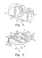
- the bearing component 16 has a proximal articulation surface 17 and a distal mounting surface 19 opposite the proximal articulation surface 17.
- the proximal articulation surface 17 of the bearing 16 includes a medial bearing surface 21 configured to articulate with the medial condyle 18 of the femoral component 12 and a lateral bearing surface 23 configured to articulate with the lateral condyle 20 of the femoral component 12.
- the bearing component 16 is modular, and is assembled with the tibial tray 14 intraoperatively and secured thereto through a mechanical interlocking mechanism, as described in more detail below.
- the tibial tray 14 includes a platform 24 having a proximal mounting surface 26 and an opposite distal bone-engaging surface 28.
- the illustrated tibial tray 14 also includes a plurality of extensions 30, 32, 34, 36, 38 extending distally from the distal bone-engaging surface 28 of the platform to distal ends 40, 42, 44, 46, 48 along axes 50, 52, 54, 56, 58 intersecting the distal surface 28 of the platform 24.
- Each extension 30, 32, 34, 36, 38 has an axial length, shown, for example, as L 1 and L 2 in FIG. 5 .
- Each extension 30, 32, 34, 36, 38 also has an exterior surface comprising a proximal exterior surface 60, 62, 64, 66, 68 adjacent to the distal surface 28 of the tibial platform 24 and a distal exterior surface 70, 72, 74, 76, 78 at the distal ends 40, 42, 44, 46, 48 of the extensions.
- the distal exterior surfaces 70, 72, 74, 76, 78 of the extensions 30, 32, 34, 36, 38 extend proximally from the distal ends 40, 42, 44, 46, 48 of the extensions at least part of the axial length of each extension 30, 32, 34, 36, 38.
- the distal exterior surfaces 70, 72, 74, 76, 78 of the stem 30 and pegs 32, 34, 36 38 are generally spheroid-shaped in the device shown in this drawing.
- the tibial tray 14 is a composite of two materials, including a solid polymer portion 80 and a porous portion 82.
- solid polymer is used to identify a material that lacks void space, having substantially 100% of theoretical density.
- porous portion is used to identify a portion of the implant made of a material that has void space and that is less than 100% of theoretical density. As discussed in more detail below, the porous portion may comprise a biocompatible metal or a biocompatible polymer.
- the solid polymer portion 80 of the tibial tray 14 defines the proximal surface 26 of the platform 24 and bears against the distal surface 19 of the bearing component 16 when assembled.
- the solid polymer portion 80 extends from the proximal surface 26 of the platform into each of the extensions 30, 32, 34, 36 38, and defines the distal exterior surfaces 70, 72, 74, 76, 78 of the extensions 30, 32, 34, 36, 38.
- the polymer portion 80 of the tibial tray 14 is secured to the porous portion 82, as described in more detail below.
- the porous portion 82 of the tibial tray defines the distal bone-engaging surface 28 of the platform 24.
- This porous distal surface 28 faces the bone of the resected proximal surface of the tibial plateau, and defines a material that is conducive to bone ingrowth to allow for uncemented fixation of the tibial platform to the proximal tibia.
- the porous portion 82 extends proximally from the distal surface 28 and intermeshes with the solid polymer portion 80 at a location between the distal surface 28 and the proximal surface 26 of the platform 24.
- FIGS. 6 to 8 An embodiment of a first example of the porous portion 82 of a tibial tray 14, prior to being moulded to the solid polymer portion 80, is shown in FIGS. 6 to 8 .
- This porous portion defines a base or preform 84 that has an upper surface 86 opposite from the distal surface 28.
- the upper surface 86 is generally flat and planar, and becomes the interface with the solid polymer portion 80 of the tray when the porous base or preform is moulded with the polymer to make the tibial tray 14.
- the porous base or preform 84 also defines the proximal exterior surface 60, 62, 64, 66, 68 of each of the extensions 30, 32, 34, 36, 38.
- the proximal exterior surfaces 60, 62, 64, 66, 68 extend distally out from the bone-engaging distal surface 28 of the base or preform 84.
- the upper surface 86 of the first porous base or preform 84 has a series of five holes or openings 90, 92, 94, 96, 98. These holes or openings correspond with the extensions 30, 32, 34, 36, 38.
- the extensions 30, 32, 34, 36, 38 of the first embodiment define a stem 30 and four spaced pegs 32, 34, 36, 38.
- the stem 30 and pegs 32, 34, 36, 38 are configured to be implanted into a surgically prepared end of a patient's tibia (not shown).
- FIGS. 9 to 13 Additional embodiments of porous metal preforms 84A, 84B are illustrated in FIGS. 9 to 13 .
- the base or preform has three holes or openings 90A, 90B, 92A, 92B, 96A, 96B.
- a tibial tray made with from such a base or preform 84A, 84B, shown in FIGS. 12 and 13 at 14A and 14B, would have a stem 90A, 90B and two pegs 92A, 92B, 96A, 96B.
- the number and shapes of the extensions can be varied.
- FIGS. 9 to 13 like reference numerals have been used for parts corresponding with the first illustrated embodiment, followed by the letter “A” for the first alternative embodiment of FIGS. 9 to 12 and the letter “B” for the second alternative embodiment of FIG. 13 .
- the description of the first embodiment applies to these alternative embodiments, except where distinctions are drawn.
- the porous preform or base need not include any portions extending distally beyond the distal surface 28, 28A of the preform.
- a tibial tray formed from the preform 84A of FIGS. 9 to 11 would appear similar to the tray 14A shown in FIG. 12 ; in this embodiment, the porous portion 82A of the tray 14A does not define any portion of the extensions 30A, 32A, 34A, 36A, 38A, 40A; instead the porous portion 82A defines a portion of the platform 28A of the tibial tray only.
- the entire length of each of the extensions 30A, 32A, 34A, 36A, 38A, 40A in the embodiment of FIG. 12 comprise parts of the solid polymer portion 80A of the tibial tray 14A.
- the extensions of the tibial tray need not all be the same.
- the central stem extension 30B of the tray 14B has a proximal exterior surface 60B that is part of the porous portion 82B of the tray 14B, with the distal exterior surface 70B being part of the polymer portion 80B of the tray 14B; the exterior surfaces of the other extensions 92B and 96B in the embodiment of FIG. 13 are part of the solid polymer portion of the tray 14B along their entire exposed length.
- each extension 30, 32, 34, 36, 38, 30A, 32A, 36A, 30B, 32B, 36B is defined by the solid polymer portion 80, 80A, 80B of the tray 14, 14A, 14B. As shown in the cross-sections of FIGS.
- the solid polymer portion 80, 80A, 80B extends through the cavity defined by the interior surfaces 100, 102, 104, 106, 108, 100A, 102A, 106A, 100B, 102B, 106B at each hole 90, 92, 94, 96, 98, 90A, 92A, 96A, 90B, 92B, 96B and extends to the distal exterior surface 40, 42, 44, 46, 48, 40A, 42A, 46A, 40B, 42B, 46B of each extension 30, 32, 34, 36, 38, 30A, 32A, 36A, 30B, 32B, 36B.
- the solid polymer portions 80, 80A, 80B of the illustrated tibial trays 14, 14A, 14B may comprise a reinforced bio-stable and biocompatible polymer, such as fibre-reinforced PEEK (polyetheretherketone).
- PEEK polyetheretherketone
- An example of a suitable material is PEEK reinforced with carbon fibres or glass fibres.
- a commercially available carbon fibre reinforced PEEK material is available from Invibio Inc. of West Conshohocken, Pennsylvania and Invibio Limited Corporation of Lancashire, United Kingdom (www.invibio.com) under the trade mark PEEK-OPTIMA.
- the carbon-reinforced PEEK supplied by Invibio is available with different concentrations of carbon fibre and Invibio reports different elastic moduli for the different concentrations: 20% carbon fibre by weight having an elastic or flexural modulus of 15 GPa, 30% carbon fibre by weight having an elastic or flexural modulus of 19 GPA, and 60% carbon fibre by weight having an elastic or flexural modulus of 50 GPa. It should be understood that the present invention is not limited to this particular PEEK material or to PEEK material for the polymer portion unless expressly called for in the claims. It is expected that other polyarylarylketone polymers, other fibre reinforced biocompatible polymeric materials and non-reinforced biocompatible polymeric materials are or will become available that will be appropriate for use in implementing the invention.
- the biocompatible polymer may be reinforced with hydroxyapatite (HA) whiskers of various volume fractions, as disclosed in US-A-2008/206297 .
- HA hydroxyapatite
- the porous portions 82, 82A, 82B of the tibial trays 14, 14A, 14B may comprise any commonly used biostable and biocompatible metal, such as stainless steel, titanium and standard cobalt chromium and titanium alloys, or may comprise a porous biocompatible polymer.
- the porous portion 82, 82A, 82B has pores of such size, shape and number so that when the solid polymer portion 80, 80A, 80B of the tibial tray is moulded to the porous portion 82, 82A, 82B, an intermediate bonding layer is formed between the porous portion 82, 82A, 82B and the polymer portion 80, 80A, 80B.
- An example of such a structure is shown in FIG.
- porous portion 82 that does not include any material of the solid polymeric portion 80
- solid polymeric portion 80 that does not include any material of the porous portion 82
- intermediate portion 83 that includes material from both the polymeric portion 80 and the porous portion 82.
- the polymeric material from the solid polymeric portion 80 and the skeleton from the porous portion 82 interdigitate to mechanically bond the solid polymeric portion 80 to the porous portion 82. This same interdigitation would be present in the embodiments of FIGS. 9 to 13 as well.
- porous structure may be used for the porous portions 82, 82A, 82B of the tibial trays 14, 14A, 14B.
- a titanium metal foam may be used, such as the foams disclosed in US-A-2008/199720 , US-A-2010/098574 , US-A-2009/ 326674 and US-A-2009/292365 .
- Alternative materials are available.
- One example of a suitable alternative material is tantalum porous metal, disclosed, for example in US-5282861 and US-A-2009/192610 .
- a solid metal body made from an implantable metal such as stainless steel, cobalt chromium alloy, titanium, titanium alloy or the like and with a porous coating disposed on both the bone-engaging surface and the surface engaging the polymer portion of the tibial tray.
- porous coating which may be used as the porous portions 82, 82A, 82B of the tibial trays 14, 14A, 14B is that used on implant components which are available from DePuy Orthopaedics Inc of Warsaw, Indiana under the trade mark Porocoat.
- the porous metal preform 84A may be made using any of the process described above or using other processes.
- Porous biocompatible polymers are available as well.
- US-A-2008/ 206297 discloses porous biocompatible polymeric materials such as PEEK reinforced with hydroxyapatite fibres or whiskers and methods of making such materials. It is anticipated that such porous biocompatible polymers may be used for the porous portions 82, 82A, 82B of the tibial tray 14, 14A, 14B instead of metal.
- Any biocompatible material having a surface of sufficient porosity and suitable mechanical properties to form a mechanical bond with the solid polymer portion 80, 80A, 80B when moulded together may be used as the porous portion 82, 82A, 82B of the tibial tray 14, 14A, 14B.
- porous portion 82, 82A, 82B of the tibial tray 14, 14A, 14B may be desirable to incorporate additional materials into the porous portion 82, 82A, 82B of the tibial tray 14, 14A, 14B.
- a calcium phosphate such as hydroxyapatite may be coated or deposited on the porous portion 82, 82A, 82B, with or without other bioactive agents.
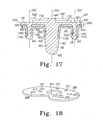
- FIGS. 17 to 22 One way of providing such additional reinforcement is illustrated in the embodiment FIGS. 17 to 22 .
- FIG. 17 is similar to FIG. 5 , with the exception that a reinforcing plate 200 is added to the composite construct.
- like reference numerals have been used for parts corresponding with the first illustrated embodiment, followed by the letter "C".
- the description of the first embodiment applies to these alternative embodiments, except where distinctions are drawn.
- the structures described below with respect to FIGS. 17 to 22 can be applied as well to the embodiments illustrated in FIGS. 9 to 13 .
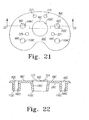
- the reinforcing plate 200 in the embodiment of FIGS. 17 to 22 is positioned between portions of a porous preform 82C and the solid polymer portion 80C of the tray 14C. As shown in FIGS. 18 to 19 , the plate 200 has an outline shaped generally the same as that of the tibial tray platform and includes a plurality of holes or bores. A large central through-bore 201 is sized, shaped and positioned to correspond with the bore 90C of the porous polymer preform 84C shown in FIGS. 20 and 21 .
- the reinforcing plate 200 has four other spaced through-bores 203, 205, 207, 209 corresponding in size, shape and position to bores 92C, 94C, 96C, 98C of the porous polymer preform 84C.
- the reinforcing plate 200 also includes four spaced through-bores 211, 213, 215, 217 sized, shaped and positioned to fit over four raised abutments 219, 221, 223, 225 extending up from the upper surface 86C of the porous polymer preform 84C. It should be understood that the reinforcing plate 200 is not necessarily drawn to scale; the thickness of the plate 200 may be varied, along with the material, to achieve the desired properties for the entire tibial tray 14C.
- the plate 200 could be made out of metal, such as standard cobalt chromium alloy, stainless steel or titanium alloy.
- the plate 200 could comprise a biocompatible polymer, such as, for example, a fibre reinforced PEEK material or any of the other polymer materials described herein.
- PEEK reinforced with carbon fibre is available in varying concentrations; one might select to make the reinforcing plate 200 out of a PEEK having one concentration of carbon fibre and make the solid polymer portion 80C out of PEEK having another concentration of carbon fibre.
- the material and dimensions (such as thickness) for the reinforcing plate 200 may be varied to provide a desired effective stiffness for the total tibial tray 14C.
- the bearing 16 is formed from a polymeric material, but comprises a different polymeric material from that used for the polymer portion of the tibial tray.
- Suitable polymeric materials for the bearing include ultrahigh molecular weight polyethylene (UHMWPE).
- UHMWPE ultrahigh molecular weight polyethylene
- the UHMWPE may comprise a cross-linked material, for example. Techniques for crosslinking, quenching, or otherwise preparing UHMWPE are disclosed in documents such as US-5728748 , US-5879400 , US-6017975 , US-6242507 , US-6316158 , US-6228900 , US-6245276 and US-6281264 .
- the UHMWPE of the bearing material may be treated to stabilize any free radicals present therein, such as through the addition of an antioxidant such as vitamin E.
- an antioxidant such as vitamin E.
- Techniques for stabilizing UHMWPE with antioxidants are disclosed in, for example, US-A-2007/0293647 and US-A-2003/021216 . It should be understood that the present invention is not limited to any particular UHMWPE material or to UHMWPE material for the bearing 16. It is expected that other materials for the bearing 16 are or will become available that will be useful in the invention.
- the first knee prosthesis is a fixed bearing prosthesis: the bearing 16 is secured to the tibial tray 14 through complementary locking features that eliminate or at least minimize any relative movement between the bearing 16 and the tibial tray 14 when these components are assembled.
- the distal surface 19 of the bearing 16 includes a lateral pedestal 134 and a medial pedestal 138.
- the pedestals 134, 138 have posterior tabs 140 defined therein.
- a number of anterior tabs 142 are also defined in the bearing 16.
- a generally Y-shaped posterior buttress 144 defines part the proximal surface 26 of the tibial tray 14.
- This posterior buttress 144 is formed in the polymer portion 80 of the tibial tray 14.
- the posterior buttress 144 has a pair of arms 146, 148 extending along a posterior section of the perimeter of the proximal surface 26 of the tray's polymer portion 80.
- the lateral arm 148 of the posterior buttress 144 extends along the posterior edge 150 on the lateral side of the polymer portion 80
- the medial arm 146 of the posterior buttress 144 extends along the posterior edge 150 on the medial side of the polymer portion 80 in a direction away from the lateral arm 148.
- a third arm 152 of the posterior buttress 144 extends anteriorly away from the intersection of the lateral arm 148 and the medial arm 146.
- the posterior buttress 144 has a pair of undercuts 154, 156 defined therein.
- the lateral undercut 154 is defined in the lateral arm 148 of the posterior buttress 144, with the medial undercut 156 being defined in the medial arm 146 of the posterior buttress 144.
- a generally T-shaped anterior buttress 164 extends upwardly from the proximal surface 26 of the tibial tray 14.
- This anterior buttress 164 is formed in the polymer portion 80 of the tibial tray 14.
- the anterior buttress 164 has a pair of arms 166, 168 extending along an anterior section of the perimeter of the proximal surface 26 of the tray's polymer portion 80.
- the lateral arm 166 of the anterior buttress 164 extends along the anterior edge 170 on the lateral side of the polymer portion 80
- the medial arm 168 of the anterior buttress 164 extends along the anterior edge 170 on the medial side of the polymer portion 80 in a direction away from the lateral arm 166.
- a third arm 172 of the anterior buttress 164 extends posteriorly away from the intersection of the lateral arm 166 and the medial arm 168.
- the anterior buttress 164 has a pair of undercuts 174, 176 defined therein.
- the lateral undercut 174 is defined in the lateral arm 166 of the anterior buttress 164, with the medial undercut 176 being defined in the medial arm 168 of the anterior buttress 164.
- the posterior buttress 144 of the tibial tray 14 is contiguous with the tray's anterior buttress 164.
- the third arm 152 of the posterior buttress 144 is contiguous with the third arm 172 of the anterior buttress 164.
- other embodiments are contemplated, including arrangements in which the buttresses are not contiguous.
- the two buttresses 144, 164 are herein described as being of a similar height, although the buttresses could be embodied as having dissimilar heights.
- the two buttresses 144, 164 may be formed in the polymer material as part of a moulding process when the solid polymer portion 80 is moulded to the porous portion 82.
- the buttresses 144, 164 may be formed by machining the polymer portion 80 after moulding the solid polymer portion and the porous portion together.
- the undercuts 154, 156, 174, 176 may be formed in the polymer portion 80 by moulding, machining or other suitable process. Some combination of moulding and machining could also be used to form the buttresses 144, 164 and undercuts 154, 156, 174, 176.
- the posterior tabs 140 of the bearing 16 are positioned in the posterior undercuts 154, 156 of the tibial tray 14.
- the anterior portion of the tibial bearing 16 is then advanced downwardly toward the tibial tray 14 such that the anterior tabs 142 of the tibial bearing 16 are deflected by the anterior buttress 164 and thereafter snapped into the anterior undercuts 174, 176 of the anterior buttress thereby securing the bearing 16 to the tray 14.
- the anterior portion of the bearing 16 is advanced downwardly in such a manner, the buttresses 144, 164 of the tibial tray 14 are captured between the pedestals 134, 138 of the bearing's distal surface 19.
- the distal surface 19 of the bearing 16 has a posterior recess 178 and an anterior recess 180 defined therein.
- the posterior recess 178 is configured to compliment the shape of the posterior buttress 144 of the tibial tray 14. That is, when the bearing 16 is secured to the tibial tray 14, the sidewalls of the pedestals 134, 138 that define the posterior recess 178 contact the edges of the posterior buttress 144.
- anterior recess 180 is configured to compliment the shape of the anterior buttress 164 of the tibial tray 14, that is when the bearing 16 is secured to the tibial tray 14, the sidewalls of the pedestals 134, 138 that define the anterior recess 180 contact the edges of the anterior buttress 164.
- the dimensions of the recesses 178, 180 and the buttresses 144, 164 are selected such that a relatively tight fit is achieved. In such a way, the bearing 16 is fixed relative to the tibial tray 14.
- the configuration of the buttresses 144, 164 and the pedestals 134, 138 formed in the distal surface 19 of the bearing 16 prevent movement of the bearing 16 relative the tibial tray 14 in the anterior/posterior direction and the medial/lateral direction.
- the posterior tabs positioned in the undercuts 154, 156 and the anterior tabs 142 positioned in the undercuts 174, 176 prevent lift off of the bearing 16 from the tibial tray 14.
- Rotational micromotion is reduced, if not prevented all together, by the relatively tight fit of the buttresses 144, 164 of the tibial tray 14 into the recesses 178, 180 of the bearing 16, particularly along the third arm 152 of the posterior buttress 144 and/or the third arm 172 of the anterior buttress 164.
- a given design of a fixed-bearing knee prosthesis is typically made commercially available in a variety of different sizes, particularly in a variety of different widths. This is done to accommodate the many variations in patient size and anatomy across a population.
- the configuration of the fixed-knee prosthesis 10 of the present disclosure allows for a high degree of flexibility in regard to the sizing of the tibial tray 14 and the bearing 16.
- the location of the undercuts 154, 156 defined in posterior buttress 144, respectively, remains the same across the range of differently-sized trays 14. Even though the posterior undercuts 154, 156 remain in the same location across the range of differently-sized trays 14, the width of the arms 146, 148 is varied to accommodate the overall width of a given tray 14.
- the location of the undercuts 174, 176 defined in anterior buttress 164, respectively, remains the same across the range of differently-sized trays 14, although the width of the arms 166, 168 is varied to accommodate the overall width of a given tray 14.
- the size and configuration of the third arms 152, 172 of the posterior buttress 144 and the anterior buttress 164, respectively, remain unchanged across the range of differently-sized trays 14.
- Differently-sized bearings 16 may also be configured in such a manner.
- a plurality of the bearings 16 may be designed with each of such a plurality of bearings 16 having a different size, particularly a different width.
- each of such differently-sized bearings 16 may include mating features that are commonly-sized and commonly-located with the commonly-sized and commonly-located features of the tibial tray 14 described above.
- each of the bearings 16 across a range of differently-sized bearings may include a posterior recess 178 and an anterior recess 180 that is positioned and sized to tightly fit against the edges of the posterior buttress 144 and the anterior buttress 164, respectively, of each of the tibial trays 14 across the range of differently-sized trays 14.
- the posterior tabs 140 are commonly-sized and commonly-located across the range of differently-sized bearings 16 so that they are positioned in the respective posterior undercuts 154, 156 of each of the tibial trays 14 across the range of differently-sized trays 14.
- the anterior tabs 142 are commonly-sized and commonly-located across the range of differently-sized bearings 16 so that they are positioned in the respective anterior undercuts 174, 176 of each of the tibial trays 14 across the range of differently-sized trays 14.
- the general configuration of the buttresses 144, 164 (including contiguous variations thereof) is the same across a range of differently-sized tibial trays 14.
- the general configuration of the recesses 178, 180 (including contiguous variations thereof) and the general configuration of tabs 140, 142 are the same across a range of differently-sized bearings 16.
- a number of differently-sized bearings 16 may be secured to a given tibial tray 14. This provides the orthopaedic surgeon with greater flexibility of matching the knee prosthesis 10 to a particular patient's anatomy.
- the porous base or preform 84, 84A, 84B, 84C is first made, using any suitable process for example as described above.
- the preform 84, 84A, 84B, 84C may be placed in a suitable moulding apparatus and the material for the solid polymer portion 80, 80A, 80B, 80C (such as fibre-reinforced PEEK) then moulded onto the preform. Injection moulding, for example, may be used.
- some of the polymer flows over the proximal surface 86, 86A, 86B of the porous base or preform 84, 84A, 84B and into the holes 90, 92, 94, 96, 98, 90A, 92A, 94A, 96A, 98A, 90B, 92B, 94B, 96B, 98B of the preform.
- the polymer flows through the holes and into the channels defined by the interior surfaces 100, 102, 104, 106, 108 of the extensions 30, 32, 34, 36, 38, and out of the holes 110, 112, 114, 116, 118 at the distal ends of the porous portions of the extensions to form the polymeric distal ends 40, 42, 44, 46, 48 and distal exterior surfaces 70, 72, 74, 76, 78 of the extensions 30, 32, 34, 36, 38.
- polymer flows over the upper surface of metal plate 200 and through the through holes of the plate 201, 203, 205, 207, 209 and into the through holes 90C, 92C, 94C, 96C, 98C of the porous preform 84C and out of holes at the distal ends of the porous portions of the extensions to form the polymeric distal ends 40C, 42C, 44C, 46C, 46D, 46E and distal exterior surfaces of the extensions 30C, 32C, 34C, 34D, 34E.
- polymer also flows through the through holes 211, 213, 215, 217 of the plate 200 and into the pores of the porous polymer of the four raised abutments 219, 221, 223, 225.
- the polymer will flow into the pores of the abutments 219, 221, 223, 225 and interdigitate as shown in FIG. 14 to bond the two polymer portions 80C, 82C together, with the reinforcing plate 200 held between them.
- porous abutments 219, 221, 223, 225 represents one method of bonding the solid polymer portion 80C to the porous polymer portion 82C; differing numbers, sizes and shapes of areas in the plate 200 that allow for interdigitation of the two polymers may be used, for example.
- the locking features (such as the buttress 144 and undercuts 154, 156, 174, 176) may be moulded and/or machined or otherwise finished to form the mounting surface 26, 26A, 26B, 26C of the tibial tray 14, 14A, 14B, 14C.
- the composite tibial tray 14, 14A, 14B, 14C so manufactured can be expected to have advantageous properties.
- a tibial tray would be expected to have an effective stiffness (stiffness of the composite construct including both the porous portion 82 and the polymer portion 80) lower than that of a similarly sized and shaped tibial tray made solely of standard biocompatible metal alloys.
- an effective stiffness it is anticipated that the tibial tray of the present invention would provide optimum load transfer to the underlying bone to minimize or prevent stress shielding and the resultant bone loss.
- tibial tray 14, 14A, 14B, 14C is implanted on the prepared tibia.
- the distal mounting surface 19 of the bearing 16 contacts and bears against the proximal mounting surface 26, 26A, 26B, 26C of the tibial tray 14, 14A, 14B, 14C.
- a suitable femoral component 12 would be implanted, and would articulate with the bearing 16 as shown in FIG. 15 .
- the tibial tray 14, 14A, 14B, 14C is suitable for cementless implantation.
- bone ingrowth is also anticipated into the proximal exterior surfaces 60, 62, 64, 66, 68 of the extensions 30, 32, 34, 36, 38 adjacent to the distal surface 28 of the tibial platform 24.
- a similar result is expected for the exterior surfaces 60C, 62C, 66C of the extensions 30C, 32C, 36C and distal surface 28C illustrated in FIG. 17 .
- Radial pressure along the proximal exterior surfaces 60, 62, 64, 66, 68, 60C, 62C, 66C is expected to be uniform, to stimulate bone ingrowth in all directions on the stem and pegs 30, 32, 34, 36, 38, 30C, 32C, 36C.
- bone ingrowth should occur at the proximal end of the tibial tray but not at the distal end.
- the interfaces of the porous portion 82, 82A, 82B, 82C of the tray 14, 14A, 14B, 14C and the bone are all readily accessible from the tibial plateau.
- the central stem 30, 30A, 30B, 30C is expected to provide stability against lift off for the tibial tray.
- the pegs 32, 34, 36, 38, 32A, 36A, 32B, 36B, 32C, 36C surrounding the central stem 30, 30A, 30B, 30C are expected to reduce shear and micromotion proximally, especially after bone ingrowth has occurred.
- the surgeon may cut along the distal surface 28, 28A, 28B, 28C of the tibial tray platform 24, 24A, 24B, 24C ⁇ to sever the connection between the patient's bone and the tibial tray platform 24, 24A, 24B, 24C.
- porous portion 82, 82A, 82B, 82C of the tibial tray 14, 14A, 14B, 14C is made of a material such as a metal or polymer foam
- the surgeon may also cut through all of the extensions 30, 32, 34, 36, 38, 30A, 32A, 36A, 30B, 32B, 36B, 30C, 32C, 36C at the junctures of the extensions and the distal surface 28, 28A, 28B, 28C of the tibial platform 24, 24A, 24B, 24C and easily remove the tibial platform 24, 24A, 24B, 24C.
- each extension 30, 32, 34, 36, 38, 30C, 32C, 36C may then be cut around the outer perimeter of each extension 30, 32, 34, 36, 38, 30C, 32C, 36C to sever the connection between the bone and the porous proximal external surfaces 60, 62, 64, 66, 68, 60C, 62C, 66C of the extensions 30, 32, 34, 36, 38, 30C, 32C, 36C.
- Each extension may then be readily removed.
- the amount of bone that needs to be resected should be substantially less compared to a system that uses fully porous stems and pegs.
- the present invention provide a knee prosthesis with a modular tibial implant component suitable for cementless fixation.
- the tibial implant component can be readily removed from the bone in revision surgery to conserve native bone.
- the tibial implant can also have a modulus of elasticity less than that of conventional solid titanium and cobalt chromium alloy trays.
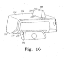
- FIG. 16 An example of such ajoint prosthesis is an ankle prosthesis as shown in FIG. 16 , which comprises a talar component 212, a composite distal tibial component 214 and a bearing 216.
- the composite distal tibial component 214 comprises a distal solid polymer portion 220 and a proximal porous portion 222, bonded together as described above for the knee prosthesis 10.
- the solid polymer portion 220 and the bearing have mounting surfaces with complementary locking features (not shown) so that the bearing 216 can be fixed to the tibial component 214.
- the illustrated distal tibial component 214 has a proximal extension 224 extending proximally from the bone-engaging surface 226 of the tibial component 214.
- the proximal extension 224 may provide polymeric outer surfaces for engaging the bone or the distal portion 228 may comprise porous material and the proximal portion 230 comprise solid polymer.
- Implant components discussed above might have surfaces that do not contact bone or another part of the implant component.
- peripheral surface 250, 250A, 250B, 250C of the tibial tray 14, 14A, 14B, 14C extends between the bone-engaging surface 28, 28A, 28B, 28C and the proximal mounting surface 26, 26A, 26B, 26C.
- the porous portion 82C has reduced outer dimensions compared to the solid polymer portion 80C to prevent contact with soft tissue. Essentially, a substantial part of the porous portion 82C fits within a pocket in the solid polymer portion 80C, while a part of the porous portion 82C stands proud to thereby ensure that the surface 28C fully engages and transfers load to the underlying bone.
Landscapes
- Health & Medical Sciences (AREA)
- Orthopedic Medicine & Surgery (AREA)
- Cardiology (AREA)
- Oral & Maxillofacial Surgery (AREA)
- Transplantation (AREA)
- Engineering & Computer Science (AREA)
- Biomedical Technology (AREA)
- Heart & Thoracic Surgery (AREA)
- Vascular Medicine (AREA)
- Life Sciences & Earth Sciences (AREA)
- Animal Behavior & Ethology (AREA)
- General Health & Medical Sciences (AREA)
- Public Health (AREA)
- Veterinary Medicine (AREA)
- Physical Education & Sports Medicine (AREA)
- Prostheses (AREA)
- Materials For Medical Uses (AREA)
Priority Applications (1)
| Application Number | Priority Date | Filing Date | Title |
|---|---|---|---|
| EP13160460.5A EP2606857A1 (de) | 2009-10-30 | 2010-10-26 | Prothese mit Verbundstoffkomponente |
Applications Claiming Priority (2)
| Application Number | Priority Date | Filing Date | Title |
|---|---|---|---|
| US25651709P | 2009-10-30 | 2009-10-30 | |
| US12/620,034 US8128703B2 (en) | 2007-09-28 | 2009-11-17 | Fixed-bearing knee prosthesis having interchangeable components |
Publications (2)
| Publication Number | Publication Date |
|---|---|
| EP2319462A1 true EP2319462A1 (de) | 2011-05-11 |
| EP2319462B1 EP2319462B1 (de) | 2013-04-03 |
Family
ID=43587257
Family Applications (2)
| Application Number | Title | Priority Date | Filing Date |
|---|---|---|---|
| EP20100188965 Not-in-force EP2319462B1 (de) | 2009-10-30 | 2010-10-26 | Prothese mit Verbundstoffkomponente |
| EP13160460.5A Withdrawn EP2606857A1 (de) | 2009-10-30 | 2010-10-26 | Prothese mit Verbundstoffkomponente |
Family Applications After (1)
| Application Number | Title | Priority Date | Filing Date |
|---|---|---|---|
| EP13160460.5A Withdrawn EP2606857A1 (de) | 2009-10-30 | 2010-10-26 | Prothese mit Verbundstoffkomponente |
Country Status (7)
| Country | Link |
|---|---|
| EP (2) | EP2319462B1 (de) |
| JP (1) | JP5752392B2 (de) |
| CN (1) | CN102058446A (de) |
| AU (1) | AU2010237755B2 (de) |
| DK (1) | DK2319462T3 (de) |
| ES (1) | ES2406366T3 (de) |
| ZA (1) | ZA201007773B (de) |
Cited By (9)
| Publication number | Priority date | Publication date | Assignee | Title |
|---|---|---|---|---|
| EP3287101A1 (de) * | 2016-08-24 | 2018-02-28 | Howmedica Osteonics Corp. | Peek-femurkomponente mit segmentiertem einwachsen von ti-schaum |
| CN110198684A (zh) * | 2017-05-04 | 2019-09-03 | 瑞特医疗技术公司 | 具有支柱的骨骼植入物 |
| WO2019186505A1 (en) * | 2018-03-30 | 2019-10-03 | DePuy Synthes Products, Inc. | Hybrid fixation features for three-dimensional porous structures for bone ingrowth and methods for producing |
| CN112807133A (zh) * | 2021-02-07 | 2021-05-18 | 西安市红会医院 | 基于3d打印的距骨坏死表面置换假体 |
| US11364123B2 (en) | 2018-03-26 | 2022-06-21 | Depuy Ireland Unlimited Company | Three-dimensional porous structures for bone ingrowth and methods for producing |
| WO2022129848A1 (en) * | 2020-12-14 | 2022-06-23 | Invibio Knees Limited | Knee implant |
| CN114828783A (zh) * | 2019-12-17 | 2022-07-29 | 德普伊爱尔兰无限公司 | 整形外科膝关节假体的金属背衬膝盖骨组件及其相关联的制造方法 |
| US11517438B2 (en) | 2019-09-25 | 2022-12-06 | Depuy Ireland Unlimited Company | Three-dimensional porous structures for bone ingrowth and methods for producing |
| US11890200B2 (en) | 2018-03-30 | 2024-02-06 | Depuy Ireland Unlimited Company | Surface textures for three-dimensional porous structures for bone ingrowth and methods for producing |
Families Citing this family (19)
| Publication number | Priority date | Publication date | Assignee | Title |
|---|---|---|---|---|
| EP3332748B1 (de) | 2010-07-24 | 2019-08-14 | Zimmer, Inc. | Asymmetrische tibiakomponenten für eine knieprothese |
| WO2012034033A1 (en) | 2010-09-10 | 2012-03-15 | Zimmer, Inc. | Motion facilitating tibial components for a knee prosthesis |
| US8690954B2 (en) | 2011-11-18 | 2014-04-08 | Zimmer, Inc. | Tibial bearing component for a knee prosthesis with improved articular characteristics |
| US20140277183A1 (en) * | 2013-03-15 | 2014-09-18 | Smed-Ta/Td, Llc | Fixation of orthopaedic devices |
| US9408699B2 (en) * | 2013-03-15 | 2016-08-09 | Smed-Ta/Td, Llc | Removable augment for medical implant |
| US9925052B2 (en) | 2013-08-30 | 2018-03-27 | Zimmer, Inc. | Method for optimizing implant designs |
| GB201400287D0 (en) * | 2014-01-08 | 2014-02-26 | Depuy Ireland | Femoral component of a knee joint prosthesis |
| CN104887355B (zh) * | 2015-05-08 | 2017-05-03 | 江苏奥康尼医疗科技发展有限公司 | 一种人工膝关节胫骨托 |
| CN105640671A (zh) * | 2016-03-03 | 2016-06-08 | 华中科技大学同济医学院附属同济医院 | 一种单髁人工膝关节 |
| DE102016114059A1 (de) | 2016-07-29 | 2018-02-01 | Aesculap Ag | Implantat und Gelenkimplantat |
| ES2878003T3 (es) | 2017-03-10 | 2021-11-18 | Zimmer Inc | Prótesis tibial con característica de afianzamiento para un componente de apoyo tibial |
| EP4487819B1 (de) | 2017-05-12 | 2026-03-25 | Zimmer, Inc. | Femurprothesen mit vergrösserungs- und verkleinerungskapazität |
| US10835380B2 (en) | 2018-04-30 | 2020-11-17 | Zimmer, Inc. | Posterior stabilized prosthesis system |
| ES3041139T3 (en) * | 2018-12-07 | 2025-11-07 | Smed Ta Td Llc | Patellofemoral implant with porous ingrowth material |
| EP3711714A1 (de) * | 2019-03-19 | 2020-09-23 | Limarcorporate S.p.A. | Schienbeinplatte einer schienbeinkomponente einer knieprothese, schienbeinkomponente mit der schienbeinplatte und verfahren zur herstellung der schienbeinplatte |
| ES2966660T3 (es) * | 2019-02-28 | 2024-04-23 | Limacorporate Spa | Placa de base tibial para componente tibial de una prótesis de rodilla, componente tibial que comprende la placa de base tibial y método de fabricación de la placa de base tibial |
| US12226317B2 (en) | 2019-12-17 | 2025-02-18 | Depuy Ireland Unlimited Company | Metal-backed tibial component of an orthopaedic knee prosthesis and associated method of making the same |
| US12569347B2 (en) | 2023-03-29 | 2026-03-10 | Depuy Ireland Unlimited Company | Metal-reinforced polymer femoral component of an orthopaedic knee prosthesis and associated method of making the same |
| CN117224289B (zh) * | 2023-11-14 | 2024-02-20 | 北京爱康宜诚医疗器材有限公司 | 一种非对称膝关节假体及其制备方法 |
Citations (27)
| Publication number | Priority date | Publication date | Assignee | Title |
|---|---|---|---|---|
| US5176710A (en) * | 1991-01-23 | 1993-01-05 | Orthopaedic Research Institute | Prosthesis with low stiffness factor |
| US5282861A (en) | 1992-03-11 | 1994-02-01 | Ultramet | Open cell tantalum structures for cancellous bone implants and cell and tissue receptors |
| US5728748A (en) | 1993-06-01 | 1998-03-17 | Howmedica Inc. | Non oxidizing polymeric medical implant |
| US5879400A (en) | 1996-02-13 | 1999-03-09 | Massachusetts Institute Of Technology | Melt-irradiated ultra high molecular weight polyethylene prosthetic devices |
| US6017975A (en) | 1996-10-02 | 2000-01-25 | Saum; Kenneth Ashley | Process for medical implant of cross-linked ultrahigh molecular weight polyethylene having improved balance of wear properties and oxidation resistance |
| US6228900B1 (en) | 1996-07-09 | 2001-05-08 | The Orthopaedic Hospital And University Of Southern California | Crosslinking of polyethylene for low wear using radiation and thermal treatments |
| US6245276B1 (en) | 1999-06-08 | 2001-06-12 | Depuy Orthopaedics, Inc. | Method for molding a cross-linked preform |
| US6281264B1 (en) | 1995-01-20 | 2001-08-28 | The Orthopaedic Hospital | Chemically crosslinked ultrahigh molecular weight polyethylene for artificial human joints |
| US20030021216A1 (en) | 1999-12-24 | 2003-01-30 | Hendriks Bernardus Hendrikus Wilhelmus | Optical element |
| US20070255412A1 (en) * | 2006-04-18 | 2007-11-01 | Binyamin Hajaj | Prosthetic device |
| US20070293647A1 (en) | 2000-04-27 | 2007-12-20 | Orthopaedic Hospital | Oxidation-resistant and wear-resistant polyethylenes for human joint replacements and methods for making them |
| US20080109081A1 (en) * | 2003-10-22 | 2008-05-08 | Qi-Bin Bao | Joint Arthroplasty Devices Having Articulating Members |
| US20080199720A1 (en) | 2007-02-21 | 2008-08-21 | Depuy Products, Inc. | Porous metal foam structures and methods |
| US20080206297A1 (en) | 2007-02-28 | 2008-08-28 | Roeder Ryan K | Porous composite biomaterials and related methods |
| US20080255675A1 (en) * | 2007-04-13 | 2008-10-16 | Sidebotham Christopher G | Bone-compliant femoral stem |
| US20090032664A1 (en) | 2007-08-01 | 2009-02-05 | Samsung Electronics Co., Ltd. | Supporting device for display apparatus and display apparatus having the same |
| US20090082873A1 (en) | 2007-09-25 | 2009-03-26 | Hazebrouck Stephen A | Fixed-bearing knee prosthesis |
| US20090192610A1 (en) | 2008-01-30 | 2009-07-30 | Zimmer, Inc. | Orthopedic component of low stiffness |
| US20090292365A1 (en) | 2008-05-22 | 2009-11-26 | Depuy Products, Inc. | Implants With Roughened Surfaces |
| US7628818B2 (en) | 2007-09-28 | 2009-12-08 | Depuy Products, Inc. | Fixed-bearing knee prosthesis having interchangeable components |
| US20090326674A1 (en) | 2008-06-30 | 2009-12-31 | Depuy Products, Inc. | Open Celled Metal Implants With Roughened Surfaces and Method for Roughening Open Celled Metal Implants |
| US20090326667A1 (en) | 2008-06-30 | 2009-12-31 | Williams John L | Orthopaedic femoral component having controlled condylar curvature |
| US20090326666A1 (en) | 2008-06-30 | 2009-12-31 | Wyss Joseph G | Posterior stabilized orthopaedic prosthesis |
| US20090326665A1 (en) | 2008-06-30 | 2009-12-31 | Wyss Joseph G | Posterior stabilized orthopaedic knee prosthesis having controlled condylar curvature |
| US20100036500A1 (en) | 2008-06-30 | 2010-02-11 | Heldreth Mark A | Orthopaedic knee prosthesis having controlled condylar curvature |
| WO2010045537A1 (en) * | 2008-10-17 | 2010-04-22 | Biomet Manufacturing Corp. | Tibial tray having a reinforcing member |
| US20100098574A1 (en) | 2008-08-27 | 2010-04-22 | Liu Hengda D | Mixtures For Forming Porous Constructs |
Family Cites Families (12)
| Publication number | Priority date | Publication date | Assignee | Title |
|---|---|---|---|---|
| JPS62500634A (ja) * | 1984-10-09 | 1987-03-19 | エ−・ビ− アイデア | 関節プロテーゼの固着方法 |
| US4938769A (en) * | 1989-05-31 | 1990-07-03 | Shaw James A | Modular tibial prosthesis |
| US5755800A (en) * | 1996-12-23 | 1998-05-26 | Johnson & Johnson Professional, Inc. | Modular joint prosthesis augmentation system |
| KR100358193B1 (ko) * | 2000-02-16 | 2002-10-25 | 한국과학기술원 | 시멘트 비사용 인공관절 스템용 플라스틱 자켓 및 이것을 구비한 인공관절 |
| DE10157782A1 (de) * | 2001-11-28 | 2003-06-12 | Schunk Kohlenstofftechnik Gmbh | Implantat sowie Verfahren zum Herstellen eines solchen |
| US6740186B2 (en) * | 2002-02-20 | 2004-05-25 | Zimmer Technology, Inc. | Method of making an orthopeadic implant having a porous metal surface |
| US20040002767A1 (en) * | 2002-06-28 | 2004-01-01 | Joseph Wyss | Modular knee joint prosthesis |
| US7175665B2 (en) * | 2002-09-09 | 2007-02-13 | Depuy Products, Inc. | Universal tibial augment |
| US9237958B2 (en) * | 2004-06-30 | 2016-01-19 | Synergy Disc Replacement Inc. | Joint prostheses |
| US7896921B2 (en) * | 2004-12-30 | 2011-03-01 | Depuy Products, Inc. | Orthopaedic bearing and method for making the same |
| EP2205188B1 (de) * | 2007-09-25 | 2014-04-09 | Biomet Manufacturing Corp. | Zementfreies tibiaplateau |
| US7988736B2 (en) * | 2008-02-27 | 2011-08-02 | Biomet Manufacturing Corp. | Method and apparatus for providing resorbable fixation of press-fit implants |
-
2010
- 2010-10-26 EP EP20100188965 patent/EP2319462B1/de not_active Not-in-force
- 2010-10-26 ES ES10188965T patent/ES2406366T3/es active Active
- 2010-10-26 DK DK10188965T patent/DK2319462T3/da active
- 2010-10-26 EP EP13160460.5A patent/EP2606857A1/de not_active Withdrawn
- 2010-10-29 JP JP2010243402A patent/JP5752392B2/ja not_active Expired - Fee Related
- 2010-10-29 ZA ZA2010/07773A patent/ZA201007773B/en unknown
- 2010-10-29 AU AU2010237755A patent/AU2010237755B2/en not_active Ceased
- 2010-11-01 CN CN201010542701XA patent/CN102058446A/zh active Pending
Patent Citations (29)
| Publication number | Priority date | Publication date | Assignee | Title |
|---|---|---|---|---|
| US5176710A (en) * | 1991-01-23 | 1993-01-05 | Orthopaedic Research Institute | Prosthesis with low stiffness factor |
| US5282861A (en) | 1992-03-11 | 1994-02-01 | Ultramet | Open cell tantalum structures for cancellous bone implants and cell and tissue receptors |
| US5728748A (en) | 1993-06-01 | 1998-03-17 | Howmedica Inc. | Non oxidizing polymeric medical implant |
| US6281264B1 (en) | 1995-01-20 | 2001-08-28 | The Orthopaedic Hospital | Chemically crosslinked ultrahigh molecular weight polyethylene for artificial human joints |
| US5879400A (en) | 1996-02-13 | 1999-03-09 | Massachusetts Institute Of Technology | Melt-irradiated ultra high molecular weight polyethylene prosthetic devices |
| US6228900B1 (en) | 1996-07-09 | 2001-05-08 | The Orthopaedic Hospital And University Of Southern California | Crosslinking of polyethylene for low wear using radiation and thermal treatments |
| US6242507B1 (en) | 1996-10-02 | 2001-06-05 | Depuy Orthopaedics, Inc. | Process for medical implant of cross-linked ultrahigh molecular weight polyethylene having improved balance of wear properties and oxidation resistance |
| US6017975A (en) | 1996-10-02 | 2000-01-25 | Saum; Kenneth Ashley | Process for medical implant of cross-linked ultrahigh molecular weight polyethylene having improved balance of wear properties and oxidation resistance |
| US6316158B1 (en) | 1996-10-02 | 2001-11-13 | Depuy Orthopaedics, Inc. | Process for medical implant of cross-linked ultrahigh molecular weight polyethylene having improved balance of wear properties and oxidation resistance |
| US6245276B1 (en) | 1999-06-08 | 2001-06-12 | Depuy Orthopaedics, Inc. | Method for molding a cross-linked preform |
| US20030021216A1 (en) | 1999-12-24 | 2003-01-30 | Hendriks Bernardus Hendrikus Wilhelmus | Optical element |
| US20070293647A1 (en) | 2000-04-27 | 2007-12-20 | Orthopaedic Hospital | Oxidation-resistant and wear-resistant polyethylenes for human joint replacements and methods for making them |
| US20080109081A1 (en) * | 2003-10-22 | 2008-05-08 | Qi-Bin Bao | Joint Arthroplasty Devices Having Articulating Members |
| US20070255412A1 (en) * | 2006-04-18 | 2007-11-01 | Binyamin Hajaj | Prosthetic device |
| US20080199720A1 (en) | 2007-02-21 | 2008-08-21 | Depuy Products, Inc. | Porous metal foam structures and methods |
| US20080206297A1 (en) | 2007-02-28 | 2008-08-28 | Roeder Ryan K | Porous composite biomaterials and related methods |
| US20080255675A1 (en) * | 2007-04-13 | 2008-10-16 | Sidebotham Christopher G | Bone-compliant femoral stem |
| US20090032664A1 (en) | 2007-08-01 | 2009-02-05 | Samsung Electronics Co., Ltd. | Supporting device for display apparatus and display apparatus having the same |
| US20090082873A1 (en) | 2007-09-25 | 2009-03-26 | Hazebrouck Stephen A | Fixed-bearing knee prosthesis |
| US7628818B2 (en) | 2007-09-28 | 2009-12-08 | Depuy Products, Inc. | Fixed-bearing knee prosthesis having interchangeable components |
| US20090192610A1 (en) | 2008-01-30 | 2009-07-30 | Zimmer, Inc. | Orthopedic component of low stiffness |
| US20090292365A1 (en) | 2008-05-22 | 2009-11-26 | Depuy Products, Inc. | Implants With Roughened Surfaces |
| US20090326674A1 (en) | 2008-06-30 | 2009-12-31 | Depuy Products, Inc. | Open Celled Metal Implants With Roughened Surfaces and Method for Roughening Open Celled Metal Implants |
| US20090326667A1 (en) | 2008-06-30 | 2009-12-31 | Williams John L | Orthopaedic femoral component having controlled condylar curvature |
| US20090326666A1 (en) | 2008-06-30 | 2009-12-31 | Wyss Joseph G | Posterior stabilized orthopaedic prosthesis |
| US20090326665A1 (en) | 2008-06-30 | 2009-12-31 | Wyss Joseph G | Posterior stabilized orthopaedic knee prosthesis having controlled condylar curvature |
| US20100036500A1 (en) | 2008-06-30 | 2010-02-11 | Heldreth Mark A | Orthopaedic knee prosthesis having controlled condylar curvature |
| US20100098574A1 (en) | 2008-08-27 | 2010-04-22 | Liu Hengda D | Mixtures For Forming Porous Constructs |
| WO2010045537A1 (en) * | 2008-10-17 | 2010-04-22 | Biomet Manufacturing Corp. | Tibial tray having a reinforcing member |
Cited By (23)
| Publication number | Priority date | Publication date | Assignee | Title |
|---|---|---|---|---|
| AU2017218986B2 (en) * | 2016-08-24 | 2022-03-10 | Howmedica Osteonics Corp. | Peek femoral component with segmented ti foam in-growth |
| US10639160B2 (en) | 2016-08-24 | 2020-05-05 | Howmedica Osteonics Corp. | Peek femoral component with segmented TI foam in-growth |
| US11642222B2 (en) | 2016-08-24 | 2023-05-09 | Howmedica Osteonics Corp. | Peek femoral component with segmented Ti foam in-growth |
| EP3287101A1 (de) * | 2016-08-24 | 2018-02-28 | Howmedica Osteonics Corp. | Peek-femurkomponente mit segmentiertem einwachsen von ti-schaum |
| CN110198684A (zh) * | 2017-05-04 | 2019-09-03 | 瑞特医疗技术公司 | 具有支柱的骨骼植入物 |
| US12138170B2 (en) | 2017-05-04 | 2024-11-12 | Wright Medical Technology, Inc. | Bone implant with struts |
| EP3551138A4 (de) * | 2017-05-04 | 2020-09-09 | Wright Medical Technology, Inc. | Knochenimplantate mit streben |
| US11090162B2 (en) | 2017-05-04 | 2021-08-17 | Wright Medical Technology, Inc. | Bone implant with struts |
| US11364123B2 (en) | 2018-03-26 | 2022-06-21 | Depuy Ireland Unlimited Company | Three-dimensional porous structures for bone ingrowth and methods for producing |
| US12485014B2 (en) | 2018-03-26 | 2025-12-02 | Depuy Ireland Unlimited Company | Three-dimensional porous structures for bone ingrowth and methods for producing |
| AU2019246736B2 (en) * | 2018-03-30 | 2024-05-30 | DePuy Synthes Products, Inc. | Hybrid fixation features for three-dimensional porous structures for bone ingrowth and methods for producing |
| US12564496B2 (en) | 2018-03-30 | 2026-03-03 | Depuy Ireland Unlimited Company | Hybrid fixation features for three-dimensional porous structures for bone ingrowth and methods for producing |
| WO2019186505A1 (en) * | 2018-03-30 | 2019-10-03 | DePuy Synthes Products, Inc. | Hybrid fixation features for three-dimensional porous structures for bone ingrowth and methods for producing |
| US11278412B2 (en) | 2018-03-30 | 2022-03-22 | Depuy Ireland Unlimited Company | Hybrid fixation features for three-dimensional porous structures for bone ingrowth and methods for producing |
| EP4112011A1 (de) * | 2018-03-30 | 2023-01-04 | DePuy Synthes Products, Inc. | Hybridbefestigungsmerkmale für dreidimensionale poröse strukturen für knocheneinwuchs und verfahren zur herstellung davon |
| CN111936088A (zh) * | 2018-03-30 | 2020-11-13 | 德普伊新特斯产品公司 | 用于骨向内生长的三维多孔结构的混合固定特征部和生产方法 |
| US11890200B2 (en) | 2018-03-30 | 2024-02-06 | Depuy Ireland Unlimited Company | Surface textures for three-dimensional porous structures for bone ingrowth and methods for producing |
| US12133801B2 (en) | 2019-09-25 | 2024-11-05 | Depuy Ireland Unlimited Company | Three-dimensional porous structures for bone ingrowth and methods for producing |
| US11517438B2 (en) | 2019-09-25 | 2022-12-06 | Depuy Ireland Unlimited Company | Three-dimensional porous structures for bone ingrowth and methods for producing |
| CN114828783A (zh) * | 2019-12-17 | 2022-07-29 | 德普伊爱尔兰无限公司 | 整形外科膝关节假体的金属背衬膝盖骨组件及其相关联的制造方法 |
| WO2022129848A1 (en) * | 2020-12-14 | 2022-06-23 | Invibio Knees Limited | Knee implant |
| EP4656163A3 (de) * | 2020-12-14 | 2026-03-11 | Invibio Knees Limited | Knieimplantat |
| CN112807133A (zh) * | 2021-02-07 | 2021-05-18 | 西安市红会医院 | 基于3d打印的距骨坏死表面置换假体 |
Also Published As
| Publication number | Publication date |
|---|---|
| JP2011092740A (ja) | 2011-05-12 |
| EP2319462B1 (de) | 2013-04-03 |
| AU2010237755B2 (en) | 2015-04-02 |
| CN102058446A (zh) | 2011-05-18 |
| AU2010237755A1 (en) | 2011-05-19 |
| DK2319462T3 (da) | 2013-07-08 |
| ZA201007773B (en) | 2012-10-31 |
| EP2606857A1 (de) | 2013-06-26 |
| ES2406366T3 (es) | 2013-06-06 |
| JP5752392B2 (ja) | 2015-07-22 |
Similar Documents
| Publication | Publication Date | Title |
|---|---|---|
| EP2319462B1 (de) | Prothese mit Verbundstoffkomponente | |
| US20110035018A1 (en) | Prosthesis with composite component | |
| US9993345B2 (en) | Femoral prosthesis system | |
| AU2022211895B2 (en) | Tibial tray with fixation features | |
| EP2316382B1 (de) | Prothese für zementfreie Verankerung | |
| AU2012217694B2 (en) | Modular prosthesis | |
| EP2777624B1 (de) | Orthopädische Prothese | |
| EP2319460A1 (de) | Prothese mit stumpfen Zapfen | |
| EP2347733A1 (de) | Knieprothesensystem | |
| US20110029090A1 (en) | Prosthesis with modular extensions | |
| US20100298947A1 (en) | Precision Total Knee Arthroplasty | |
| CA2930668C (en) | Augment system for an implant | |
| US20110035017A1 (en) | Prosthesis with cut-off pegs and surgical method | |
| WO2007123861A2 (en) | Prosthetic device | |
| US20130060344A1 (en) | Femoral component with reinforced articulating surface | |
| CN113631122A (zh) | 膝假体的胫骨组分的胫骨基板(胫骨组分包括胫骨基板)及制造胫骨基板的方法 | |
| EP2316384B1 (de) | Prothese mit modularen Erweiterungen | |
| AU2014201526B2 (en) | Mechanical assembly of titanium foam pegs | |
| US20160262898A1 (en) | Tibial implant for use in knee arthroplasty |
Legal Events
| Date | Code | Title | Description |
|---|---|---|---|
| PUAI | Public reference made under article 153(3) epc to a published international application that has entered the european phase |
Free format text: ORIGINAL CODE: 0009012 |
|
| AK | Designated contracting states |
Kind code of ref document: A1 Designated state(s): AL AT BE BG CH CY CZ DE DK EE ES FI FR GB GR HR HU IE IS IT LI LT LU LV MC MK MT NL NO PL PT RO RS SE SI SK SM TR |
|
| AX | Request for extension of the european patent |
Extension state: BA ME |
|
| 17P | Request for examination filed |
Effective date: 20111031 |
|
| 17Q | First examination report despatched |
Effective date: 20120308 |
|
| GRAP | Despatch of communication of intention to grant a patent |
Free format text: ORIGINAL CODE: EPIDOSNIGR1 |
|
| RIN1 | Information on inventor provided before grant (corrected) |
Inventor name: DEFFENBAUGH, DAREN L Inventor name: WOGOMAN, THOMAS E |
|
| GRAS | Grant fee paid |
Free format text: ORIGINAL CODE: EPIDOSNIGR3 |
|
| GRAA | (expected) grant |
Free format text: ORIGINAL CODE: 0009210 |
|
| AK | Designated contracting states |
Kind code of ref document: B1 Designated state(s): AL AT BE BG CH CY CZ DE DK EE ES FI FR GB GR HR HU IE IS IT LI LT LU LV MC MK MT NL NO PL PT RO RS SE SI SK SM TR |
|
| REG | Reference to a national code |
Ref country code: GB Ref legal event code: FG4D |
|
| REG | Reference to a national code |
Ref country code: AT Ref legal event code: REF Ref document number: 604227 Country of ref document: AT Kind code of ref document: T Effective date: 20130415 Ref country code: CH Ref legal event code: EP |
|
| REG | Reference to a national code |
Ref country code: CH Ref legal event code: NV Representative=s name: E. BLUM AND CO. AG PATENT- UND MARKENANWAELTE , CH |
|
| REG | Reference to a national code |
Ref country code: IE Ref legal event code: FG4D |
|
| REG | Reference to a national code |
Ref country code: DE Ref legal event code: R096 Ref document number: 602010005879 Country of ref document: DE Effective date: 20130529 |
|
| REG | Reference to a national code |
Ref country code: ES Ref legal event code: FG2A Ref document number: 2406366 Country of ref document: ES Kind code of ref document: T3 Effective date: 20130606 |
|
| REG | Reference to a national code |
Ref country code: SE Ref legal event code: TRGR |
|
| REG | Reference to a national code |
Ref country code: DK Ref legal event code: T3 |
|
| REG | Reference to a national code |
Ref country code: NL Ref legal event code: T3 |
|
| PG25 | Lapsed in a contracting state [announced via postgrant information from national office to epo] |
Ref country code: SI Free format text: LAPSE BECAUSE OF FAILURE TO SUBMIT A TRANSLATION OF THE DESCRIPTION OR TO PAY THE FEE WITHIN THE PRESCRIBED TIME-LIMIT Effective date: 20130403 |
|
| REG | Reference to a national code |
Ref country code: LT Ref legal event code: MG4D |
|
| PG25 | Lapsed in a contracting state [announced via postgrant information from national office to epo] |
Ref country code: GR Free format text: LAPSE BECAUSE OF FAILURE TO SUBMIT A TRANSLATION OF THE DESCRIPTION OR TO PAY THE FEE WITHIN THE PRESCRIBED TIME-LIMIT Effective date: 20130704 Ref country code: PT Free format text: LAPSE BECAUSE OF FAILURE TO SUBMIT A TRANSLATION OF THE DESCRIPTION OR TO PAY THE FEE WITHIN THE PRESCRIBED TIME-LIMIT Effective date: 20130805 Ref country code: NO Free format text: LAPSE BECAUSE OF FAILURE TO SUBMIT A TRANSLATION OF THE DESCRIPTION OR TO PAY THE FEE WITHIN THE PRESCRIBED TIME-LIMIT Effective date: 20130703 Ref country code: LT Free format text: LAPSE BECAUSE OF FAILURE TO SUBMIT A TRANSLATION OF THE DESCRIPTION OR TO PAY THE FEE WITHIN THE PRESCRIBED TIME-LIMIT Effective date: 20130403 Ref country code: IS Free format text: LAPSE BECAUSE OF FAILURE TO SUBMIT A TRANSLATION OF THE DESCRIPTION OR TO PAY THE FEE WITHIN THE PRESCRIBED TIME-LIMIT Effective date: 20130803 |
|
| PG25 | Lapsed in a contracting state [announced via postgrant information from national office to epo] |
Ref country code: LV Free format text: LAPSE BECAUSE OF FAILURE TO SUBMIT A TRANSLATION OF THE DESCRIPTION OR TO PAY THE FEE WITHIN THE PRESCRIBED TIME-LIMIT Effective date: 20130403 Ref country code: RS Free format text: LAPSE BECAUSE OF FAILURE TO SUBMIT A TRANSLATION OF THE DESCRIPTION OR TO PAY THE FEE WITHIN THE PRESCRIBED TIME-LIMIT Effective date: 20130403 Ref country code: PL Free format text: LAPSE BECAUSE OF FAILURE TO SUBMIT A TRANSLATION OF THE DESCRIPTION OR TO PAY THE FEE WITHIN THE PRESCRIBED TIME-LIMIT Effective date: 20130403 Ref country code: BG Free format text: LAPSE BECAUSE OF FAILURE TO SUBMIT A TRANSLATION OF THE DESCRIPTION OR TO PAY THE FEE WITHIN THE PRESCRIBED TIME-LIMIT Effective date: 20130703 Ref country code: CY Free format text: LAPSE BECAUSE OF FAILURE TO SUBMIT A TRANSLATION OF THE DESCRIPTION OR TO PAY THE FEE WITHIN THE PRESCRIBED TIME-LIMIT Effective date: 20130403 Ref country code: HR Free format text: LAPSE BECAUSE OF FAILURE TO SUBMIT A TRANSLATION OF THE DESCRIPTION OR TO PAY THE FEE WITHIN THE PRESCRIBED TIME-LIMIT Effective date: 20130403 |
|
| PG25 | Lapsed in a contracting state [announced via postgrant information from national office to epo] |
Ref country code: CZ Free format text: LAPSE BECAUSE OF FAILURE TO SUBMIT A TRANSLATION OF THE DESCRIPTION OR TO PAY THE FEE WITHIN THE PRESCRIBED TIME-LIMIT Effective date: 20130403 Ref country code: SK Free format text: LAPSE BECAUSE OF FAILURE TO SUBMIT A TRANSLATION OF THE DESCRIPTION OR TO PAY THE FEE WITHIN THE PRESCRIBED TIME-LIMIT Effective date: 20130403 Ref country code: EE Free format text: LAPSE BECAUSE OF FAILURE TO SUBMIT A TRANSLATION OF THE DESCRIPTION OR TO PAY THE FEE WITHIN THE PRESCRIBED TIME-LIMIT Effective date: 20130403 |
|
| PLBE | No opposition filed within time limit |
Free format text: ORIGINAL CODE: 0009261 |
|
| STAA | Information on the status of an ep patent application or granted ep patent |
Free format text: STATUS: NO OPPOSITION FILED WITHIN TIME LIMIT |
|
| PG25 | Lapsed in a contracting state [announced via postgrant information from national office to epo] |
Ref country code: RO Free format text: LAPSE BECAUSE OF FAILURE TO SUBMIT A TRANSLATION OF THE DESCRIPTION OR TO PAY THE FEE WITHIN THE PRESCRIBED TIME-LIMIT Effective date: 20130403 |
|
| 26N | No opposition filed |
Effective date: 20140106 |
|
| REG | Reference to a national code |
Ref country code: DE Ref legal event code: R097 Ref document number: 602010005879 Country of ref document: DE Effective date: 20140106 |
|
| PG25 | Lapsed in a contracting state [announced via postgrant information from national office to epo] |
Ref country code: MC Free format text: LAPSE BECAUSE OF FAILURE TO SUBMIT A TRANSLATION OF THE DESCRIPTION OR TO PAY THE FEE WITHIN THE PRESCRIBED TIME-LIMIT Effective date: 20130403 |
|
| PG25 | Lapsed in a contracting state [announced via postgrant information from national office to epo] |
Ref country code: SM Free format text: LAPSE BECAUSE OF FAILURE TO SUBMIT A TRANSLATION OF THE DESCRIPTION OR TO PAY THE FEE WITHIN THE PRESCRIBED TIME-LIMIT Effective date: 20130403 |
|
| PG25 | Lapsed in a contracting state [announced via postgrant information from national office to epo] |
Ref country code: TR Free format text: LAPSE BECAUSE OF FAILURE TO SUBMIT A TRANSLATION OF THE DESCRIPTION OR TO PAY THE FEE WITHIN THE PRESCRIBED TIME-LIMIT Effective date: 20130403 |
|
| PG25 | Lapsed in a contracting state [announced via postgrant information from national office to epo] |
Ref country code: MK Free format text: LAPSE BECAUSE OF FAILURE TO SUBMIT A TRANSLATION OF THE DESCRIPTION OR TO PAY THE FEE WITHIN THE PRESCRIBED TIME-LIMIT Effective date: 20130403 Ref country code: LU Free format text: LAPSE BECAUSE OF NON-PAYMENT OF DUE FEES Effective date: 20131026 Ref country code: HU Free format text: LAPSE BECAUSE OF FAILURE TO SUBMIT A TRANSLATION OF THE DESCRIPTION OR TO PAY THE FEE WITHIN THE PRESCRIBED TIME-LIMIT; INVALID AB INITIO Effective date: 20101026 |
|
| PG25 | Lapsed in a contracting state [announced via postgrant information from national office to epo] |
Ref country code: MT Free format text: LAPSE BECAUSE OF FAILURE TO SUBMIT A TRANSLATION OF THE DESCRIPTION OR TO PAY THE FEE WITHIN THE PRESCRIBED TIME-LIMIT Effective date: 20130403 |
|
| PGFP | Annual fee paid to national office [announced via postgrant information from national office to epo] |
Ref country code: ES Payment date: 20150915 Year of fee payment: 6 |
|
| PGFP | Annual fee paid to national office [announced via postgrant information from national office to epo] |
Ref country code: DK Payment date: 20151012 Year of fee payment: 6 |
|
| PGFP | Annual fee paid to national office [announced via postgrant information from national office to epo] |
Ref country code: FI Payment date: 20151012 Year of fee payment: 6 |
|
| PGFP | Annual fee paid to national office [announced via postgrant information from national office to epo] |
Ref country code: SE Payment date: 20151013 Year of fee payment: 6 Ref country code: AT Payment date: 20150928 Year of fee payment: 6 Ref country code: BE Payment date: 20151012 Year of fee payment: 6 Ref country code: NL Payment date: 20151012 Year of fee payment: 6 |
|
| REG | Reference to a national code |
Ref country code: FR Ref legal event code: PLFP Year of fee payment: 7 |
|
| PG25 | Lapsed in a contracting state [announced via postgrant information from national office to epo] |
Ref country code: BE Free format text: LAPSE BECAUSE OF NON-PAYMENT OF DUE FEES Effective date: 20161031 |
|
| REG | Reference to a national code |
Ref country code: DK Ref legal event code: EBP Effective date: 20161031 |
|
| REG | Reference to a national code |
Ref country code: NL Ref legal event code: MM Effective date: 20161101 |
|
| REG | Reference to a national code |
Ref country code: AT Ref legal event code: MM01 Ref document number: 604227 Country of ref document: AT Kind code of ref document: T Effective date: 20161026 |
|
| PG25 | Lapsed in a contracting state [announced via postgrant information from national office to epo] |
Ref country code: FI Free format text: LAPSE BECAUSE OF NON-PAYMENT OF DUE FEES Effective date: 20161026 |
|
| PG25 | Lapsed in a contracting state [announced via postgrant information from national office to epo] |
Ref country code: AT Free format text: LAPSE BECAUSE OF NON-PAYMENT OF DUE FEES Effective date: 20161026 Ref country code: SE Free format text: LAPSE BECAUSE OF NON-PAYMENT OF DUE FEES Effective date: 20161027 Ref country code: NL Free format text: LAPSE BECAUSE OF NON-PAYMENT OF DUE FEES Effective date: 20161101 |
|
| REG | Reference to a national code |
Ref country code: FR Ref legal event code: PLFP Year of fee payment: 8 |
|
| PG25 | Lapsed in a contracting state [announced via postgrant information from national office to epo] |
Ref country code: DK Free format text: LAPSE BECAUSE OF NON-PAYMENT OF DUE FEES Effective date: 20161031 |
|
| REG | Reference to a national code |
Ref country code: BE Ref legal event code: MM Effective date: 20161031 |
|
| PG25 | Lapsed in a contracting state [announced via postgrant information from national office to epo] |
Ref country code: ES Free format text: LAPSE BECAUSE OF NON-PAYMENT OF DUE FEES Effective date: 20161027 |
|
| REG | Reference to a national code |
Ref country code: ES Ref legal event code: FD2A Effective date: 20180626 |
|
| REG | Reference to a national code |
Ref country code: FR Ref legal event code: PLFP Year of fee payment: 9 |
|
| PG25 | Lapsed in a contracting state [announced via postgrant information from national office to epo] |
Ref country code: AL Free format text: LAPSE BECAUSE OF FAILURE TO SUBMIT A TRANSLATION OF THE DESCRIPTION OR TO PAY THE FEE WITHIN THE PRESCRIBED TIME-LIMIT Effective date: 20130403 |
|
| PGFP | Annual fee paid to national office [announced via postgrant information from national office to epo] |
Ref country code: FR Payment date: 20190913 Year of fee payment: 10 |
|
| PGFP | Annual fee paid to national office [announced via postgrant information from national office to epo] |
Ref country code: IE Payment date: 20191010 Year of fee payment: 10 Ref country code: DE Payment date: 20191015 Year of fee payment: 10 |
|
| PGFP | Annual fee paid to national office [announced via postgrant information from national office to epo] |
Ref country code: IT Payment date: 20191009 Year of fee payment: 10 |
|
| PGFP | Annual fee paid to national office [announced via postgrant information from national office to epo] |
Ref country code: CH Payment date: 20191015 Year of fee payment: 10 |
|
| PGFP | Annual fee paid to national office [announced via postgrant information from national office to epo] |
Ref country code: GB Payment date: 20191024 Year of fee payment: 10 |
|
| REG | Reference to a national code |
Ref country code: DE Ref legal event code: R119 Ref document number: 602010005879 Country of ref document: DE |
|
| REG | Reference to a national code |
Ref country code: CH Ref legal event code: PL |
|
| GBPC | Gb: european patent ceased through non-payment of renewal fee |
Effective date: 20201026 |
|
| PG25 | Lapsed in a contracting state [announced via postgrant information from national office to epo] |
Ref country code: FR Free format text: LAPSE BECAUSE OF NON-PAYMENT OF DUE FEES Effective date: 20201031 Ref country code: DE Free format text: LAPSE BECAUSE OF NON-PAYMENT OF DUE FEES Effective date: 20210501 |
|
| PG25 | Lapsed in a contracting state [announced via postgrant information from national office to epo] |
Ref country code: LI Free format text: LAPSE BECAUSE OF NON-PAYMENT OF DUE FEES Effective date: 20201031 Ref country code: GB Free format text: LAPSE BECAUSE OF NON-PAYMENT OF DUE FEES Effective date: 20201026 Ref country code: CH Free format text: LAPSE BECAUSE OF NON-PAYMENT OF DUE FEES Effective date: 20201031 |
|
| PG25 | Lapsed in a contracting state [announced via postgrant information from national office to epo] |
Ref country code: IT Free format text: LAPSE BECAUSE OF NON-PAYMENT OF DUE FEES Effective date: 20201026 Ref country code: IE Free format text: LAPSE BECAUSE OF NON-PAYMENT OF DUE FEES Effective date: 20201026 |