EP2319675A1 - Procédé de fabrication d'un ensemble récipient et ensemble récipient - Google Patents
Procédé de fabrication d'un ensemble récipient et ensemble récipient Download PDFInfo
- Publication number
- EP2319675A1 EP2319675A1 EP09252565A EP09252565A EP2319675A1 EP 2319675 A1 EP2319675 A1 EP 2319675A1 EP 09252565 A EP09252565 A EP 09252565A EP 09252565 A EP09252565 A EP 09252565A EP 2319675 A1 EP2319675 A1 EP 2319675A1
- Authority
- EP
- European Patent Office
- Prior art keywords
- support
- frame
- injecting
- container assembly
- cavity
- Prior art date
- Legal status (The legal status is an assumption and is not a legal conclusion. Google has not performed a legal analysis and makes no representation as to the accuracy of the status listed.)
- Withdrawn
Links
- 238000004519 manufacturing process Methods 0.000 title claims abstract description 20
- 239000000463 material Substances 0.000 claims abstract description 126
- 238000000034 method Methods 0.000 claims abstract description 39
- -1 polypropylene Polymers 0.000 claims description 29
- 239000004743 Polypropylene Substances 0.000 claims description 16
- 239000004698 Polyethylene Substances 0.000 claims description 15
- 229920001155 polypropylene Polymers 0.000 claims description 13
- 229920000573 polyethylene Polymers 0.000 claims description 10
- 229920008790 Amorphous Polyethylene terephthalate Polymers 0.000 claims description 9
- 238000004891 communication Methods 0.000 claims description 7
- 239000012530 fluid Substances 0.000 claims description 7
- 229920000728 polyester Polymers 0.000 claims description 6
- 229920001684 low density polyethylene Polymers 0.000 claims description 5
- 239000004702 low-density polyethylene Substances 0.000 claims description 5
- 239000004793 Polystyrene Substances 0.000 claims description 3
- 229920002223 polystyrene Polymers 0.000 claims description 3
- 238000007789 sealing Methods 0.000 description 14
- 238000002347 injection Methods 0.000 description 10
- 239000007924 injection Substances 0.000 description 10
- 239000000203 mixture Substances 0.000 description 9
- 230000008901 benefit Effects 0.000 description 6
- 238000004806 packaging method and process Methods 0.000 description 6
- 239000007789 gas Substances 0.000 description 5
- 229920001903 high density polyethylene Polymers 0.000 description 5
- 239000004700 high-density polyethylene Substances 0.000 description 5
- 239000010410 layer Substances 0.000 description 5
- 229920001707 polybutylene terephthalate Polymers 0.000 description 5
- 229920000139 polyethylene terephthalate Polymers 0.000 description 5
- 239000005020 polyethylene terephthalate Substances 0.000 description 5
- 229920001179 medium density polyethylene Polymers 0.000 description 4
- 239000004701 medium-density polyethylene Substances 0.000 description 4
- 238000000465 moulding Methods 0.000 description 4
- 238000005452 bending Methods 0.000 description 3
- 238000001746 injection moulding Methods 0.000 description 3
- 229920000092 linear low density polyethylene Polymers 0.000 description 3
- 239000004707 linear low-density polyethylene Substances 0.000 description 3
- 239000004626 polylactic acid Substances 0.000 description 3
- BLDFSDCBQJUWFG-UHFFFAOYSA-N 2-(methylamino)-1,2-diphenylethanol Chemical compound C=1C=CC=CC=1C(NC)C(O)C1=CC=CC=C1 BLDFSDCBQJUWFG-UHFFFAOYSA-N 0.000 description 2
- 229920001577 copolymer Polymers 0.000 description 2
- 230000006378 damage Effects 0.000 description 2
- 235000013305 food Nutrition 0.000 description 2
- 230000002093 peripheral effect Effects 0.000 description 2
- 229920001083 polybutene Polymers 0.000 description 2
- 230000008569 process Effects 0.000 description 2
- 239000002344 surface layer Substances 0.000 description 2
- 229920001169 thermoplastic Polymers 0.000 description 2
- 239000004416 thermosoftening plastic Substances 0.000 description 2
- 229920001862 ultra low molecular weight polyethylene Polymers 0.000 description 2
- 229920001866 very low density polyethylene Polymers 0.000 description 2
- 239000004925 Acrylic resin Substances 0.000 description 1
- 229920003312 Appeel® Polymers 0.000 description 1
- VGGSQFUCUMXWEO-UHFFFAOYSA-N Ethene Chemical compound C=C VGGSQFUCUMXWEO-UHFFFAOYSA-N 0.000 description 1
- 239000004708 Very-low-density polyethylene Substances 0.000 description 1
- 230000000712 assembly Effects 0.000 description 1
- 238000000429 assembly Methods 0.000 description 1
- 239000003086 colorant Substances 0.000 description 1
- 238000011109 contamination Methods 0.000 description 1
- 230000008602 contraction Effects 0.000 description 1
- HDERJYVLTPVNRI-UHFFFAOYSA-N ethene;ethenyl acetate Chemical class C=C.CC(=O)OC=C HDERJYVLTPVNRI-UHFFFAOYSA-N 0.000 description 1
- QHZOMAXECYYXGP-UHFFFAOYSA-N ethene;prop-2-enoic acid Chemical class C=C.OC(=O)C=C QHZOMAXECYYXGP-UHFFFAOYSA-N 0.000 description 1
- 239000005038 ethylene vinyl acetate Substances 0.000 description 1
- 238000000605 extraction Methods 0.000 description 1
- 238000011010 flushing procedure Methods 0.000 description 1
- 230000007246 mechanism Effects 0.000 description 1
- 229920001526 metallocene linear low density polyethylene Polymers 0.000 description 1
- 238000012986 modification Methods 0.000 description 1
- 230000004048 modification Effects 0.000 description 1
- 230000035699 permeability Effects 0.000 description 1
- 230000000704 physical effect Effects 0.000 description 1
- 229920001200 poly(ethylene-vinyl acetate) Polymers 0.000 description 1
- 229920000747 poly(lactic acid) Polymers 0.000 description 1
- 229920005989 resin Polymers 0.000 description 1
- 239000011347 resin Substances 0.000 description 1
- 238000004513 sizing Methods 0.000 description 1
- 238000003860 storage Methods 0.000 description 1
Images



Classifications
-
- B—PERFORMING OPERATIONS; TRANSPORTING
- B29—WORKING OF PLASTICS; WORKING OF SUBSTANCES IN A PLASTIC STATE IN GENERAL
- B29C—SHAPING OR JOINING OF PLASTICS; SHAPING OF MATERIAL IN A PLASTIC STATE, NOT OTHERWISE PROVIDED FOR; AFTER-TREATMENT OF THE SHAPED PRODUCTS, e.g. REPAIRING
- B29C45/00—Injection moulding, i.e. forcing the required volume of moulding material through a nozzle into a closed mould; Apparatus therefor
- B29C45/16—Making multilayered or multicoloured articles
- B29C45/1676—Making multilayered or multicoloured articles using a soft material and a rigid material, e.g. making articles with a sealing part
-
- B—PERFORMING OPERATIONS; TRANSPORTING
- B29—WORKING OF PLASTICS; WORKING OF SUBSTANCES IN A PLASTIC STATE IN GENERAL
- B29C—SHAPING OR JOINING OF PLASTICS; SHAPING OF MATERIAL IN A PLASTIC STATE, NOT OTHERWISE PROVIDED FOR; AFTER-TREATMENT OF THE SHAPED PRODUCTS, e.g. REPAIRING
- B29C45/00—Injection moulding, i.e. forcing the required volume of moulding material through a nozzle into a closed mould; Apparatus therefor
- B29C45/14—Injection moulding, i.e. forcing the required volume of moulding material through a nozzle into a closed mould; Apparatus therefor incorporating preformed parts or layers, e.g. injection moulding around inserts or for coating articles
- B29C45/14754—Injection moulding, i.e. forcing the required volume of moulding material through a nozzle into a closed mould; Apparatus therefor incorporating preformed parts or layers, e.g. injection moulding around inserts or for coating articles being in movable or releasable engagement with the coating, e.g. bearing assemblies
-
- B—PERFORMING OPERATIONS; TRANSPORTING
- B29—WORKING OF PLASTICS; WORKING OF SUBSTANCES IN A PLASTIC STATE IN GENERAL
- B29C—SHAPING OR JOINING OF PLASTICS; SHAPING OF MATERIAL IN A PLASTIC STATE, NOT OTHERWISE PROVIDED FOR; AFTER-TREATMENT OF THE SHAPED PRODUCTS, e.g. REPAIRING
- B29C45/00—Injection moulding, i.e. forcing the required volume of moulding material through a nozzle into a closed mould; Apparatus therefor
- B29C45/16—Making multilayered or multicoloured articles
- B29C45/1635—Making multilayered or multicoloured articles using displaceable mould parts, e.g. retractable partition between adjacent mould cavities
- B29C45/1639—Removable partitions between adjacent mould cavity portions
-
- B—PERFORMING OPERATIONS; TRANSPORTING
- B65—CONVEYING; PACKING; STORING; HANDLING THIN OR FILAMENTARY MATERIAL
- B65D—CONTAINERS FOR STORAGE OR TRANSPORT OF ARTICLES OR MATERIALS, e.g. BAGS, BARRELS, BOTTLES, BOXES, CANS, CARTONS, CRATES, DRUMS, JARS, TANKS, HOPPERS, FORWARDING CONTAINERS; ACCESSORIES, CLOSURES, OR FITTINGS THEREFOR; PACKAGING ELEMENTS; PACKAGES
- B65D77/00—Packages formed by enclosing articles or materials in preformed containers, e.g. boxes, cartons, sacks or bags
- B65D77/10—Container closures formed after filling
- B65D77/20—Container closures formed after filling by applying separate lids or covers, i.e. flexible membrane or foil-like covers
- B65D77/2024—Container closures formed after filling by applying separate lids or covers, i.e. flexible membrane or foil-like covers the cover being welded or adhered to the container
- B65D77/2068—Means for reclosing the cover after its first opening
- B65D77/2072—Mechanical means
- B65D77/2088—Mechanical means attached to the cover
-
- B—PERFORMING OPERATIONS; TRANSPORTING
- B29—WORKING OF PLASTICS; WORKING OF SUBSTANCES IN A PLASTIC STATE IN GENERAL
- B29C—SHAPING OR JOINING OF PLASTICS; SHAPING OF MATERIAL IN A PLASTIC STATE, NOT OTHERWISE PROVIDED FOR; AFTER-TREATMENT OF THE SHAPED PRODUCTS, e.g. REPAIRING
- B29C45/00—Injection moulding, i.e. forcing the required volume of moulding material through a nozzle into a closed mould; Apparatus therefor
- B29C45/14—Injection moulding, i.e. forcing the required volume of moulding material through a nozzle into a closed mould; Apparatus therefor incorporating preformed parts or layers, e.g. injection moulding around inserts or for coating articles
- B29C45/14754—Injection moulding, i.e. forcing the required volume of moulding material through a nozzle into a closed mould; Apparatus therefor incorporating preformed parts or layers, e.g. injection moulding around inserts or for coating articles being in movable or releasable engagement with the coating, e.g. bearing assemblies
- B29C2045/1477—Removable inserts, e.g. the insert being peeled off after moulding
-
- B—PERFORMING OPERATIONS; TRANSPORTING
- B29—WORKING OF PLASTICS; WORKING OF SUBSTANCES IN A PLASTIC STATE IN GENERAL
- B29C—SHAPING OR JOINING OF PLASTICS; SHAPING OF MATERIAL IN A PLASTIC STATE, NOT OTHERWISE PROVIDED FOR; AFTER-TREATMENT OF THE SHAPED PRODUCTS, e.g. REPAIRING
- B29C45/00—Injection moulding, i.e. forcing the required volume of moulding material through a nozzle into a closed mould; Apparatus therefor
- B29C45/16—Making multilayered or multicoloured articles
- B29C2045/1601—Making multilayered or multicoloured articles the injected materials not being adhered or bonded to each other
-
- B—PERFORMING OPERATIONS; TRANSPORTING
- B29—WORKING OF PLASTICS; WORKING OF SUBSTANCES IN A PLASTIC STATE IN GENERAL
- B29C—SHAPING OR JOINING OF PLASTICS; SHAPING OF MATERIAL IN A PLASTIC STATE, NOT OTHERWISE PROVIDED FOR; AFTER-TREATMENT OF THE SHAPED PRODUCTS, e.g. REPAIRING
- B29C45/00—Injection moulding, i.e. forcing the required volume of moulding material through a nozzle into a closed mould; Apparatus therefor
- B29C45/0081—Injection moulding, i.e. forcing the required volume of moulding material through a nozzle into a closed mould; Apparatus therefor of objects with parts connected by a thin section, e.g. hinge, tear line
-
- B—PERFORMING OPERATIONS; TRANSPORTING
- B29—WORKING OF PLASTICS; WORKING OF SUBSTANCES IN A PLASTIC STATE IN GENERAL
- B29L—INDEXING SCHEME ASSOCIATED WITH SUBCLASS B29C, RELATING TO PARTICULAR ARTICLES
- B29L2031/00—Other particular articles
- B29L2031/712—Containers; Packaging elements or accessories, Packages
Definitions
- the present invention relates to a method of manufacturing a container assembly and a container assembly.
- the container assembly is a reclosable package, such as a reclosable food package.
- the container assembly may be hermetically sealed with a flexible cover.
- Hermetically sealed containers such as trays with a flexible lid sealed around their edges, are widely used in the packaging of food products.
- This type of packaging offers several advantages: the rigidity of the container provides protection to the contents of the package during transportation, storage and handling, and the hermeticity of the seals contributes to the increase in the shelf-life of the product.
- Reclosable packages are convenient for a variety of reasons. For example when the packaged product is not immediately consumed after opening of the package, it could undergo contamination and spoilage. To avoid this inconvenience consumers are often forced to time-consuming repackaging operations.
- WO 2005/039997 discloses a reclosable rigid container assembly which comprises a support and a frame in which the support comprises a peripheral flange outwardly extending from the support.
- the frame comprises a rim and is shaped at its edge to co-operate with the flange to be realisably secured onto the support wherein the container assembly is in the closed state.
- the rim of the frame extends over a fraction of the flange thus leaving a central area of the support and the remaining part of the flange not covered by the rim of the frame.
- the frame is separate from the support and in another embodiment the frame is attached to the support by a hinge.
- a flexible cover is sealed to the frame and the peripheral flange and can be removed from the flange by removing the frame from the support.
- a difficulty with the container assembly of WO 2005/039997 is that either the container assembly is made of a single material in a one-step operation (which is undesirable because this does not enable the frame to be significantly less stiff than the support, thereby making opening of the container assembly problematic) or it requires the support and frame to be made separately and connected together in a further step (this being difficult to arrange and time consuming).
- FR 2,618,411 describes a package composed of a rigid single-piece container having a ring moulded around its flange and a film sealed onto both the ring and the flange of the container. To open the package the ring is broken away from the flange of the container and the film peeled away from the flange.
- the package of this invention does not offer the required degree of reliability as there is no engagement between the frame and the flange of the container.
- a further difficulty with the container assembly of FR 2,618,411 is that the container assembly is made of a single material, thereby making it difficult to achieve the required degree of stiffness of the container whilst achieving the required degree of flexibility of the frame to allow peeling off of the film which seals the container assembly.
- An object of the present invention is to provide a method of manufacturing a container assembly comprising a support and frame. Another objective is to provide a container assembly, preferably one which can be manufactured in a one-step manufacturing method.
- a method of manufacturing together a support and frame of a container assembly comprising: providing a single mould with a first cavity defining the support and a second cavity defining the frame; injecting first material into the first cavity; and injecting second material into the second cavity; wherein the first and second materials are different materials.
- the frame and the support can be manufactured together in the same mould and do not need to be manufactured separately even though the frame and support are made of different materials. This is achieved by providing a single mould with first and second cavities which define the support and frame respectively.
- the first cavity and second cavity are adjacent so that the frame and support are moulded in place with the frame extending around the side walls of the support.
- a user may then open the container assembly by bending the frame over the support thereby breaking a seal between the flexible cover and the support.
- the support may be re-closed by replacing the frame with attached flexible cover onto the support. During this whole procedure the flexible cover remains attached to the frame.
- the frame is attached to the support. This helps during transport as well as during application of the flexible cover to ensure that the frame and support do not get detached from one another.
- the frame may be attached to the support by at least one member extending between the support and the frame, wherein the member is breakable with a lower force than the frame and support so that by breaking the at least one member the frame can be moved from its position surrounding the support. This is advantageous because then the frame does not need to over lie (for example lie on) the support. This frees up the choice of materials which can be used for making the frame and the support.
- a hinge between the frame and the container may be formed such that when the member is broken the frame can be rotated relative to the support without becoming detached from the support.
- the frame may be attached to the support in a removable way, for example by a mechanical interlock between a part of the frame and a part of the support, for example by mechanical clipping. This is advantageous as it allows the frame to be replaced back on the support after opening of the support.
- the first and second materials are incompatible such that they do not bond to one another. That is, they do not bond together during the method of the invention.
- the first material comprises a low density polyethylene or rubber modified polypropylene.
- the second material comprises amorphous polyethylene terephthalate, desirably mono amorphous polyethylene terephthalate. It is advantageous to use these materials if there is overlap between the frame and the support (e.g. the frame lies on the support). This is because those two materials are incompatible and when one is over injected or injected next to another, no sealing between those two materials occurs (e.g. no bond is made between these materials). Furthermore these materials have desirable stiffnesses for their respective rolls.
- the first material is less stiff than the second material, preferably wherein the first material has a flexural modulus in the range of 900 to 3500 MPa and/or the second material has a flexural modulus in the range of 90 to 700 MPa.
- This allows easy opening of the container assembly by bending of the frame back on itself, for example through 180°, when removing from the support a film attached to the frame and the support. Without being able to bend the frame through a large angle, it becomes difficult to remove the film from the support.
- injecting the first material is performed after injecting the second material or vice versa.
- the method may further comprise moving part of the mould between injecting the first material and injecting the second material thereby to bring the first and second cavities into fluid communication.
- injecting the first material and injecting the second material are performed concurrently.
- the delay between injecting first and second materials may be short, not allowing enough time for the material injected first fully to set, or may be long enough for the material injected first partially or fully to set.
- a method of manufacturing a container assembly comprising a frame and a support, the method comprising: providing one of the frame and the support; over injecting the other of the frame and the support on the one of the frame and the support; wherein materials of the frame and the support are incompatible such that they do not bond to one another during the over injecting.
- the material of the frame is a polyethylene and a material of the support is a polyester, a polypropylene or a polystyrene.
- the material of the support is a polypropylene.
- the material of the frame is a polypropylene and the material of the support is a polyester. In that case, preferably the material of the frame is a rubber modified polypropylene.
- the material of the support is a polyethylene terephthalate, a polybutylene terephthalate or a polylactic acid.
- the material of the support is an amorphous polyethylene terephthalate, desirable a mono amorphous polyethylene terephthalate.
- the material of the frame is a low density polyethylene or a rubber modified polyethylene.
- the material of the support is an amorphous polyethylene terephthalate and the frame is a polyethylene or rubber modified polypropylene.
- these materials which are incompatible so that on over injecting the other of the frame and the support onto the one of the frame and the support, no seal is created between the frame and the support. Additionally, these materials have the required physical properties such that the frame can be made to be less stiff than the support relatively easily.
- a container assembly comprising a frame and a support, wherein the support is for supporting a product and comprises a bottom wall and upwardly extending side walls with a flange, said frame extends around the perimeter of the flange and does not lie on top of the flange, wherein at least one member extends between the support and the frame to connect the frame to the support and which member is breakable with a lower force than the frame and support so that by breaking the at least one member the frame can be moved from its position surrounding the support, wherein the frame is of a material different to the material of the support and the material of the frame has a lower stiffness than the material of the support.
- This container has the advantage that the frame and support can be made of materials which are compatible (e.g. bond when they come into contact during the method). That is, the materials seal to one another when at least one of them is in the molten state. Therefore, such a container assembly can be made by the method of claim 1 either by injecting the frame and support at the same time or injecting them one after the other. The container assembly could also be made by the method of claim 13.
- the range of materials which can be used for a container according to this aspect is large as any level of compatibility allows the container to be made.
- a mechanical interlock exists between the support and the frame such that the frame is attachable to the support even after breaking of the at least one member. This is desirable because the support may then be sealed shut with some certainty after having first been opened.
- the mechanical interlock is present before the at least one member is broken. This allows the dimensions of the parts of the frame and support forming the mechanical overlock to be optimally designed such that a good closure of the container after the at least one member has been broken is possible.
- the container comprises a hinge between the frame and the support so that movement of the frame from its position surrounding the support comprises a rotational movement.
- the frame and support may be comprised of different grades of polyethylene.
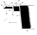
- Figure 1 is a cut-away perspective view of one embodiment of a container assembly 1 of the present invention.
- the container assembly 1 may be a rigid or semi-rigid container assembly 1.
- the container assembly 1 comprises a support 10 and a frame 20.
- Support 10 comprises a bottom wall 12 and upwardly extending side-walls 14.
- a flange 16 may be formed at an upper end of the side-walls 14. The flange 16 extends radially outwardly of the side-walls 14.
- the flange 16 is for attaching a flexible cover 30 thereto from above thereby to seal any product placed in the support 10.
- the flexible cover 30 is sealed to the flange 16 along seal line 35 which is a seal which can easily be broken without substantial damage to the flexible cover 30 or the flange 16 (e.g. it is an easy open seal).
- the flange 16 forms the periphery of the support 10.
- the flange 16 comprises a horizontal surface which extends around the side walls 14 of the support 10 and allows the flexible cover 30 to be adhered thereto.
- Frame 20 includes a rim 22 which may be flat.
- the flexible cover 30 is sealed to the rim 22 along seal 37.
- the seal 37 is preferably a more permanent (e.g. stronger) seal than seal 35.
- a gap 29 is present between the frame 20 and the support 10 for the majority of the circumference of the support.
- the frame 20 does not overlie the support 10.
- the gap 29 is only not present by way of members 40 or a hinge described below in relation to Figure 2 .
- the frame 20 also includes a skirt 24.
- the skirt 24 is shaped to engage with the flange 16 of the support 10 when the container assembly 1 is in the closed state. However, the frame 20 may engage (e.g. mechanically interlock) with the support 10 in a different way.
- On the opposite side of the rim 22 to the skirt 26 is an optional downwardly projecting flange 28 which serves to stiffen the frame.
- the skirt 24 is provided with a radially inwardly extending projection 26 which makes the inner radius of the frame 20 less than it would be without the projection 26.
- the projection 26 thereby engages with the flange 16 to form a mechanical interlock so that a user, after breaking the seal between the flexible cover 30 and the flange 16 can re-close the container assembly 1 by replacing the frame 20 on the support 10 into the position illustrated in Figure 1 .
- the projection 26 desirably projects from the skirt 24 by 1.3-1.5 mm and is placed about 2 mm (axially) from the flange 16.
- the mould may not have a mechanical interlock of the frame 20 and support 10, but this may be achieved after removal of those components from the mould by thermal contraction of the frame 20 as it cools.
- the frame 20 realisably engages with the support 10 by means of an interlocking groove-projection mechanism whereby a projection on the frame 20 fits into a groove on the support 10 or vice versa.
- Frame 20 defines a central opening, so that, when container assembly 1 is in the closed state, the support 10 remains uncovered by frame 20 and products can be as easily loaded onto the support 10 as they would be onto any conventional container.
- container assembly 1 When container assembly 1 is in the closed state it is also possible neatly to stack one assembly 1 into the other, as generally done with rigid or semi-rigid containers. This offers two major advantages: the container assemblies 1 of the present invention can be stored and shipped in a most space-efficient way and once they arrive at the packaging facility they can be fed to the packaging machine by any conventional loading equipment.
- container assembly 1 has a rounded rectangular shape however any other desired shape, such as square, round, elliptical etc., can be foreseen for the container assembly 1.
- Support 10 can be either in the form of a tray, with a bottom wall and upwardly extending side-walls (as shown in Figure 1 ) or in the form of a flat or substantially flat dish.
- a "framed" tray (container assembly 1)
- the customer may use such an assembly in a conventional lidding machine (i.e. a machine that seals a flexible cover 30 as a lid to a tray/container flange).
- a conventional lidding machine i.e. a machine that seals a flexible cover 30 as a lid to a tray/container flange.
- the flexible cover By sealing the flexible cover to both the support flange 16 and the frame 20 he may obtain a hermetically sealed package (because the film is hermetically sealed to the support flange 16) that - once opened by peeling such a seal - can then be reclosed by re-positioning the frame (with the flexible cover 30 still attached thereto) in its original position.
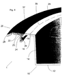
- the support 10 and frame 20 are connected by a hinge, although more than one hinge may be present. In the embodiment illustrated, the support 10 and frame 20 are not connected by any hinge.
- the frame 20 may be provided with a tab 42 which can be grasped for separating the frame 20 from the support 10.
- the frame 20 may be bent through 180° thereby to remove the flexible cover 30 from the support 10 whilst the flexible cover 30 remains attached to the frame 20.
- container assembly 1 with frame 20 engaged with support 10 is placed in a container-like counter support present in a suitable packaging machine.
- the product to be packaged is loaded into the container assembly 1 through the central opening defined by frame and through an open mouth of support 10. This can be done either manually or by means of a tray loading apparatus.
- a flexible cover 30 e.g. a thermoplastic film is then positioned over container assembly 1 and the product in the support 10.
- the flexible cover 30 can be in the form of a continuous web or can be supplied in the form of separate individual die- cut lids of a suitable size and shape.
- the atmosphere in the support 10 can be modified either by simply flushing container assembly 1 with the product loaded therein with a suitable gas or gas mixture or by firstly evacuating it and then back-filling with a suitable gas or gas mixture.
- the flexible cover 30 is then sealed over container assembly 1.
- flexible cover 30 is preferably chosen to have a low permeability to gases in order to maintain the atmosphere inside the package unchanged for the whole shelf-life of the product.
- flexible cover 30 forms a first seal 37 with rim 22 of frame 20 and a second seal 35 with the surface of the flange 16 and support 10, as shown in Figure 1 .
- both seals 37 and 35 extend around the whole perimeter of rim 22 of frame 20 and of the flange 16, respectively.
- a peelable seal refers to a seal which is strong enough to guarantee the hermeticity of the package during its life-cycle but which can be easily opened by tearing apart by hand the two materials that were joined by the seal.
- Peelable seals can be obtained, for instance, by sealing together layers of poorly compatible materials or by forming at least one of the layers of the materials joined by the seal with a blend of immiscible or partly immiscible materials.
- Said layer can be either a heat-sealable surface layer or a layer adjacent to the heat-sealable surface layer and characterized by low cohesive strength. Similar blends are often referred to as “peelable blends”.
- the force required to tear apart the two layers is usually referred to in terms of "peel force”.
- a method of measuring the peel force is described in ASTM F-88-00. Acceptable peel force values for peelable seals usually range from 1,900 g/25 mm to 700 g/25 mm.
- the force required to peel flexible cover 30 from the container assembly at seal 37 can be comparable to, or preferably higher than the force required to peel flexible cover 30 from the container assembly 1 at seal 35.
- seal 37 is a permanent seal, that is a seal that can not be opened without causing the physical destruction of at least one of the materials joined by the seal.
- Several methods can be employed to form a permanent seal 37 and a peelable seal 35 between flexible cover 30 and container assembly 1.
- the flexible cover 30 may be made of a material such as a modified ethylene vinyl acetate resin or copolymer or a modified ethylene acrylate resin or copolymer, for example. Such materials are available from Du Pont under the trademark Appeel (RTM).
- the flange 16 could be embossed so that, regardless of the compatibility between the sealing surface of flexible cover 30 and the material of container assembly 1, the seal in the roughened surface could be easily openable.
- This packaging method can be performed on currently available tray lidding machines, either automatic or manual, commercially supplied by, e.g., Ross Industries, Inc., Multivac, Inc. or Mondini S.p.A. with only minor modifications. Specific examples of suitable models include the Multivac@ T550 or the Mondini Evolutation Super.
- sealing of the thermoplastic film onto the sealing surface of the support is carried out by means of a sealing frame, which forms a continuous seal around the perimeter of the sealing surface of the support. Sealing can be accomplished by any method known in the art, for instance by hot-bar, impulse, RF etc.
- a sealing frame 70 can be formed by two separate concentric frames: one for sealing flexible cover 30 onto rim 22 of frame 20 and one for sealing the flexible cover 30 onto the flange 16 of the support 10.
- the flexible cover 30 may be cut to the desired size at any time, prior to, during or after it is sealed to container assembly 1.
- Such a means is illustrated in Figure 2 and comprises one or more (breakable) members 40 which extend between the frame 20 and the support 10 thereby to attach the frame 20 to the support 10.
- the members extend over gap 29.
- the member 40 is dimensioned such that it is breakable with a lower force than the frame 20 and support 10 (e.g. it is a breakable member) without damaging the flexible cover 30 or support 10 so that by breaking the at least one member 40 the frame 20 can be moved from its position surrounding the support 10.
- the members 40 When a user wishes to gain access to the product placed in the support 10, the members 40 are broken so that the frame 20 can then be bent backwards (or the members 40 are broken during bending backwards of the frame 20) and the flexible cover 30 peeled off from the support 20 (by breaking seal 35) by movement of the frame 20. Because of the configuration of the frame 20 and support 10, even if the seals 35, 37 are of the same strength (or seal 37 is weaker than seal 35), seal 35 will break in preference to seal 37. When the user wishes to reclose the container assembly 1, the frame 20 with the flexible cover 30 still adhered can be pushed back over the flange 16 of the support 10.
- the presence of the flexible cover 30 prevents the frame 20 from falling further downwards and the mechanical interlock formed by the projection 26 and the flange 16 prevents the flexible cover 30 from easily being lifted off from the support 10, for example by a gust of wind or during handling by the end user.
- the container assembly 1 has, in one embodiment, at least four members in the case where the frame is not hinged to the support 10. If the frame 20 is hinged to the support 10, and open along three sides, then in one embodiment a minimum of two members 40 are present. The function of the members 40 is to keep the frame 20 in position on the support 10 during pack closing.
- the frame 20 may be made of a material which is less stiff than the material of the support 10.
- the frame 20 is more flexible and the tray 10 more rigid.
- the frame 20 may be bent through 180° thereby facilitating removal of the flexible cover 30 from the flange 16.
- the flexural modulus of the frame may range from 90 to 700 MPa, preferably from 100 to 500 MPa and most preferably from 150 to 400 MPa. This compares to a range of 900 to 3500 MPa flexural modulus for the support 10.
- the materials of the frame 20 and support 10 are compatible (e.g.
- the support 10 and frame 20 could be made from the same type of material (for example polyethylene) of different grades (e.g. having different densities).
- the frame could be made of low density polyethylene and support 10 of high density polyethylene.
- Different grades of polyethylene include one or more of the following: 1) medium density polyethylene (“MDPE”), for example having a density of from 0.926 to 0.94 g/cm3; 2) linear medium density polyethylene (“LMDPE”), for example having a density of from 0.926 to 0.94 g/cm3; 3) linear low density polyethylene (“LLDPE”), for example having a density of from 0.915 to 0.930 g/cm3; and 4) very-low or ultra-low density polyethylene (“VLDPE” and "ULDPE”), for example having density below 0.915 g/cm3.
- MDPE medium density polyethylene
- LLDPE linear medium density polyethylene
- LLDPE linear low density polyethylene
- VLDPE very-low or ultra-low density polyethylene
- ULDPE ultra-low density polyethylene
- the support 10 has a thickness of around 600-700 ⁇ m, but may be up to 1 mm or more.
- the members 40 may have a smaller thicknesses, for example down to 0.3 mm. A range of from 0.3-1.5 mm is possible and a desired range is 0.3-1 mm.
- the member 40 is made of the same material as the support 10 because that material is more rigid. However, the member 40 could also be made of the more flexible material coming from the frame 20.
- the frame has a typical thickness of the range of 0.5-1.5 mm, preferably 0.5-1 mm. Different sections of the frame 20 may have different thicknesses.
- the container of Figures 1 and 2 can be manufactured in a single mould as is described below with reference to Figure 3 . It is possible to inject the frame 20 and the support 10 in a single mould using different materials for the frame 20 and support 10 (bi-component injection moulding).
- the container assembly 1 is optimised in order to allow breakage of the members 40 between the frame 20 and the support 10 when opened by the final customer and reclosability after extraction of part of the product.
- this is achieved by injection moulding both the support 10 and the frame 20 in the same mould 100.
- This can be achieved because there is no overlap between the frame 20 and the support 10. That is, contrary to what is disclosed in WO 2005/039997 , the frame 20 does not sit on top of the flange 16 of the support 10. This allows materials which would otherwise stick to each other to be injected at the same time or injected shortly one after the other into the same mould 100 because of the presence of gap 29 between the frame 20 and the flange 16. If there were no gap 29 (for example if the frame 20 sat on top of the support 10), the two materials when they are injected would adhere to one another, unless the two materials are incompatible. However, providing incompatible materials reduces the choice of materials available for use and might deleteriously increase manufacturing costs.
- a single mould 100 is provided.
- a first cavity 110 in the mould defines the desired shape of the support 10.
- a first material may be injected into the first cavity 110 through a first inlet 111.
- a second cavity 120 is defined in the mould.
- the second cavity 120 has the desired shape of the frame 20.
- the second material can be injected into the second cavity 120 through a second inlet 121.
- material is injected into the first cavity 110 at the same time that the second material is injected into the second cavity 120.
- the two materials may be different so that the timing and pressure of injection may need to be controlled in order to ensure that all or at least the majority of the frame 20 comprises the second material and all or majority of the support 10 comprises the first material.
- the first cavity 110 and second cavity 120 are adjacent so that the frame 20 and support 10 are moulded in place with the frame 10 extending around the side walls 14 of the support 10 as in the assembled state illustrated in Figure 1 .
- This has the advantage that no further steps need to be taken after the container assembly 1 is removed from the mould 100 (for example placing of the frame 20 onto the support 10).
- the frame 20 is attached to the support 10 through at least one member 40.
- each corner of the package There may be two members 40 at each corner of the package, as illustrated.
- the frame 20 is not hinged to the support 10
- the gap 29 is present between the frame 20 and the flange 16.
- the first cavity 110 may be in fluid communication with the second cavity 120.
- One location would be at a hinge between the support 10 and the frame 20.
- Other locations are at the members 40.
- These locations where there is fluid communication may be blocked by a moveable member 125 of the mould 100. This allows moulding of the support 10 and frame 20 one after the other (i.e. not at the same time but without opening the mould 100 between moulding the frame and container). That is, one of the support 10 and frame 20 are injected first whilst the moveable member 125 blocks fluid communication between the first and second cavities 110, 120.
- the moveable member 125 is then moved so that fluid communication exists between the first and second cavities 110, 120, one of which is already filled with material.
- the other of the first and second cavities 110, 120 are then injected with material. Because the first and second materials are compatible they will seal together at the locations where the moveable member 125 has been removed. Thereby it becomes possible to form a container assembly according to Figures 1 and 2 in which the support 10 and frame 20 are made of different materials but are still connected together.
- Figure 4 illustrates a further embodiment which is the same as the embodiment illustrated in Figures 1 and 2 except as described below.
- a projection 25 of the frame engages with (e.g. lies on) an outward and downward extending part 18 of the flange 16 thereby to prevent the frame from falling downwards in the absence of the film 30.
- This embodiment is likely to be without a hinge between the support 10 and frame 20.
- the first and second cavities 110, 120 are provided in fluid communication with one another. Bi-component injection moulding or injection of a first material in the first cavity and a second material in the second cavity one shortly after the other (or vice versa) is possible (with or without a moveable member 125) provided that the materials used for the frame 20 and support 10 are incompatible. Incompatible means materials which do not seal to one another when bi-component injection moulded or injected shortly one after another (e.g. in the method of the invention).
- one of the support 10 and frame 20 is provided in its completed form and the other of the frame 20 and support 10 are then over injected onto one of the frame 20 or support 10 which is initially provided.
- a support 10 is provided, a mould is provided which defines the frame 20 incompletely.
- the definition of the frame 20 is completed by positioning the already formed support 10 in the correct position on the mould thereby completing the definition of the frame 20.
- the material forming the frame 20 can then be injected into the mould and the frame 20 is formed in place on the support 10.
- the container assembly disclosed in WO2005/039997 may also be produced by both of the above alternative ways of manufacturing the container assembly 1 of Figure 4 .
- Figures 5 and 6 illustrate the manufacture of a container assembly according to WO2005/039997 using an over injection method. The same method may be used to manufacture the container assembly of Figure 4 .
- the difference between the container assembly of WO2005/039997 and that of Figure 4 is that the flange 16 of the WO2005/039997 support 10 is stepped to have two levels.
- An inner portion of the frame 20 lies on top of the lower part of the flange 16.
- the top surface of the flange 16 (which is an innermost part of the flange 16) is substantially coplanar with a top surface of the frame 20.
- the flexible cover 30 is sealed to the frame 20 and the support 10 in substantially the same plane.
- the frame 20 has a flange which abuts with the outward and downward extending part 18 of the flange 16 of the support 10.
- a projection similar to the projection 26 of the Figure 4 embodiment engages the frame 20 with the flange 16.
- the support 10 is first manufactured and the frame 20 then over injected onto the support 10.
- the frame 20 being manufactured first and support 10 being over injected onto the frame 20.
- the mould 225 may be made of more than one part 230, 240 at least one of which may be moveable.
- a member 250 may be provided to engage with and move the support 10 into place.
- the member 250 may also support the support 10 during injection of the second material such that the support 10 does not deform.
- the member 250 may alternatively or additionally clamp the support 10 in place relative to the mould 225.
- part 240 of mould 225 may be movable to allow the support 10 to be engaged with the first part 230 of the mould 225 by vertical (as illustrated) movement alone. Once the support 10 is in place, horizontal movement of the second part 240 of the mould 225 can close the cavity 120 and form it into its desired shape. Once the support 10 is in place and the cavity closed, over injection of second material into the cavity 210 through inlet 121 completes the process. The frame may then be moved from the mould 225 attached in place to the support 10. In this way the container assembly can be manufactured in the assembled condition and a further assembly step is not required.
- Example materials include any polyethylenes (with the exception of HDPE which is too rigid) onto a polyester such as a polylactic acid (PLA), a polybutylene terephthalate (PBT), or a polyethylene terephthalate (PET) such as mono amorphous polyethylene terephthalate, or rubber modified polypropylene onto a polyester such as a polylactic acid (PLA), a polybutylene terephthalate (PBT), or a polyethylene terephthalate (PET) such as mono amorphous polyethylene terephthalate, or any polyethylene (with the exception of HDPE which is too rigid) onto a polypropylene support.
- the support 10 may include a polystyrene. The option with rubber modified polypropylene is preferred because rubber modified polypropylene shrinks less after moulding than PE.
- the container assembly 1 may be injected and formed without any physical link (e.g. no members 40) by injecting the frame 20 (or support 10) already clipped onto the support 10 (or tray 20).
Landscapes
- Engineering & Computer Science (AREA)
- Mechanical Engineering (AREA)
- Manufacturing & Machinery (AREA)
- Packages (AREA)
Priority Applications (3)
| Application Number | Priority Date | Filing Date | Title |
|---|---|---|---|
| EP09252565A EP2319675A1 (fr) | 2009-11-06 | 2009-11-06 | Procédé de fabrication d'un ensemble récipient et ensemble récipient |
| US13/508,132 US8778250B2 (en) | 2009-11-06 | 2010-11-02 | Method of manufacturing a container assembly and a container assembly |
| PCT/EP2010/006673 WO2011054493A1 (fr) | 2009-11-06 | 2010-11-02 | Procede de production d'ensemble recipient et ensemble recipient |
Applications Claiming Priority (1)
| Application Number | Priority Date | Filing Date | Title |
|---|---|---|---|
| EP09252565A EP2319675A1 (fr) | 2009-11-06 | 2009-11-06 | Procédé de fabrication d'un ensemble récipient et ensemble récipient |
Publications (1)
| Publication Number | Publication Date |
|---|---|
| EP2319675A1 true EP2319675A1 (fr) | 2011-05-11 |
Family
ID=42060509
Family Applications (1)
| Application Number | Title | Priority Date | Filing Date |
|---|---|---|---|
| EP09252565A Withdrawn EP2319675A1 (fr) | 2009-11-06 | 2009-11-06 | Procédé de fabrication d'un ensemble récipient et ensemble récipient |
Country Status (3)
| Country | Link |
|---|---|
| US (1) | US8778250B2 (fr) |
| EP (1) | EP2319675A1 (fr) |
| WO (1) | WO2011054493A1 (fr) |
Cited By (5)
| Publication number | Priority date | Publication date | Assignee | Title |
|---|---|---|---|---|
| NL1038469C2 (nl) * | 2010-12-22 | 2012-06-25 | Naber Beheer B V | Werkwijze voor het vervaardigen van een verpakking. |
| WO2017009340A1 (fr) * | 2015-07-15 | 2017-01-19 | Medinoxx Gmbh | Récipients et pack d'un certain nombre de récipients |
| WO2022144579A1 (fr) * | 2020-12-30 | 2022-07-07 | Universidade Do Minho | Emballage polymère injecté pour un produit sensible ou fragile et procédé associé |
| WO2022218576A1 (fr) | 2021-04-15 | 2022-10-20 | Anmed Gmbh | Distributeur de médicament |
| EP4417538A1 (fr) * | 2023-02-16 | 2024-08-21 | Spies Kunststoffe GmbH | Procédé de fabrication d'un couvercle d'emballage et couvercle d'emballage fabriqué selon ce procédé |
Families Citing this family (9)
| Publication number | Priority date | Publication date | Assignee | Title |
|---|---|---|---|---|
| US7947236B2 (en) * | 1999-12-03 | 2011-05-24 | Becton, Dickinson And Company | Device for separating components of a fluid sample |
| WO2015000775A1 (fr) | 2013-07-01 | 2015-01-08 | Nestec S.A. | Capsule pour la préparation d'une boisson telle que du café et autres |
| WO2015059022A1 (fr) * | 2013-10-22 | 2015-04-30 | Nestec S.A. | Capsule de préparation d'une boisson telle que du café et analogue |
| MX384110B (es) | 2014-10-10 | 2025-03-14 | Cryovac Inc | Aparato y proceso para el envasado de un producto. |
| JP6906855B2 (ja) * | 2016-09-01 | 2021-07-21 | 東罐興業株式会社 | 容器 |
| JP7069832B2 (ja) * | 2018-02-28 | 2022-05-18 | 大日本印刷株式会社 | 容器とそれを用いた蓋付容器 |
| CA3168889A1 (fr) * | 2020-02-14 | 2021-08-19 | Selig Sealing Products, Inc. | Element de thermoscellage |
| KR102884993B1 (ko) | 2020-05-29 | 2025-11-12 | 셀리그 실링 프로덕츠, 아이엔씨. | 토출 라이너 |
| JP7695697B2 (ja) * | 2021-07-05 | 2025-06-19 | Nasco株式会社 | 樹脂成形容器及び樹脂成形容器の製造方法 |
Citations (6)
| Publication number | Priority date | Publication date | Assignee | Title |
|---|---|---|---|---|
| US4079567A (en) * | 1976-03-04 | 1978-03-21 | Scott Paper Company | Method for making moisture impervious packaging systems |
| EP0073356A1 (fr) * | 1981-09-01 | 1983-03-09 | STAHLGRUBER Otto Gruber GmbH & Co. | Procédé pour la production d'un tube d'une matière synthétique avec un bonnet de fermeture appartenant au tube |
| FR2618411A1 (fr) | 1987-07-24 | 1989-01-27 | Valoine Sarl Charcuterie | Recipient pour emballage de denrees alimentaires, ferme par opercule arrachable et reutilisable comme couvercle |
| WO1991001213A1 (fr) * | 1989-07-14 | 1991-02-07 | Jes Tougaard Gram | Procede et appareil de fabrication d'un objet assemble |
| DE19706734A1 (de) * | 1997-02-20 | 1998-08-27 | Opel Adam Ag | Entlüftungsvorrichtung und Verfahren zu ihrer Herstellung |
| WO2005039997A1 (fr) | 2003-10-22 | 2005-05-06 | Cryovac, Inc. | Ensemble recipient rigide refermable |
Family Cites Families (18)
| Publication number | Priority date | Publication date | Assignee | Title |
|---|---|---|---|---|
| JPS5527253A (en) | 1978-08-18 | 1980-02-27 | Fuji Photo Film Co Ltd | Heat sensitizing recording sheet |
| US4440311A (en) | 1980-08-25 | 1984-04-03 | H. P. Hood Inc. | Sealed moistureproof container |
| SE453820B (sv) | 1983-03-22 | 1988-03-07 | Haustrup Plastic As | Aterforslutbar behallare |
| US4975066A (en) | 1989-06-27 | 1990-12-04 | Amp Incorporated | Coaxial contact element |
| US5705112A (en) * | 1989-07-14 | 1998-01-06 | Gram; Jes Tougaard | Procedure for the production of an assembled object |
| US4971220A (en) | 1989-12-11 | 1990-11-20 | Kimberly-Clark Corporation | Container with "stay open" lid |
| SE9003353L (sv) | 1990-10-19 | 1992-04-20 | Cerbo Ab | Foerpackning samt foerfarande foer dess foerslutning |
| JP2593402Y2 (ja) * | 1992-08-19 | 1999-04-12 | 株式会社吉野工業所 | 合成樹脂製容器 |
| US5634567A (en) | 1994-01-21 | 1997-06-03 | Polystar Packaging, Inc. | Heat bondable container closure |
| US6112928A (en) | 1995-07-28 | 2000-09-05 | Box Ease International | Foldable self-standing container with method of manufacture and bulk dispenser |
| US5846582A (en) | 1995-09-21 | 1998-12-08 | Cryovac, Inc. | Vacuum skin package for shingled food slices |
| NL1011462C2 (nl) | 1999-03-05 | 2000-09-06 | Willemsen Michael Gerard | Verstevigd deksel. |
| EP1127809A3 (fr) | 2000-02-24 | 2002-03-13 | Alcan Technology & Management AG | Emballage avec couvercle ouvrable |
| FR2827841B1 (fr) | 2001-07-27 | 2003-12-26 | Europlastiques Sa | Couvercle destine a fermer le contenant d'un emballage ainsi qu'un emballage incorporant un tel couvercle |
| GB2382569A (en) | 2001-11-30 | 2003-06-04 | Yew Tree Consultants Ltd | A closure fitment for sealing a foodstuffs container |
| US20030152669A1 (en) | 2002-01-18 | 2003-08-14 | Parimal Vadhar | Self venting peelable microwaveable vacuum skin package |
| SE524248C2 (sv) | 2002-11-25 | 2004-07-13 | Jonny Eklund | Förpackning med barriärfilm samt metod för att tillverka en sådan förpackning |
| EP1714907A1 (fr) | 2005-04-20 | 2006-10-25 | Cryovac, Inc. | Emballage refermable pour produits alimentaires |
-
2009
- 2009-11-06 EP EP09252565A patent/EP2319675A1/fr not_active Withdrawn
-
2010
- 2010-11-02 US US13/508,132 patent/US8778250B2/en not_active Expired - Fee Related
- 2010-11-02 WO PCT/EP2010/006673 patent/WO2011054493A1/fr not_active Ceased
Patent Citations (7)
| Publication number | Priority date | Publication date | Assignee | Title |
|---|---|---|---|---|
| US4079567A (en) * | 1976-03-04 | 1978-03-21 | Scott Paper Company | Method for making moisture impervious packaging systems |
| EP0073356A1 (fr) * | 1981-09-01 | 1983-03-09 | STAHLGRUBER Otto Gruber GmbH & Co. | Procédé pour la production d'un tube d'une matière synthétique avec un bonnet de fermeture appartenant au tube |
| FR2618411A1 (fr) | 1987-07-24 | 1989-01-27 | Valoine Sarl Charcuterie | Recipient pour emballage de denrees alimentaires, ferme par opercule arrachable et reutilisable comme couvercle |
| WO1991001213A1 (fr) * | 1989-07-14 | 1991-02-07 | Jes Tougaard Gram | Procede et appareil de fabrication d'un objet assemble |
| DE19706734A1 (de) * | 1997-02-20 | 1998-08-27 | Opel Adam Ag | Entlüftungsvorrichtung und Verfahren zu ihrer Herstellung |
| WO2005039997A1 (fr) | 2003-10-22 | 2005-05-06 | Cryovac, Inc. | Ensemble recipient rigide refermable |
| US20070272688A1 (en) * | 2003-10-22 | 2007-11-29 | Eugenio Longo | Reclosable Rigid Container Assembly |
Cited By (11)
| Publication number | Priority date | Publication date | Assignee | Title |
|---|---|---|---|---|
| NL1038469C2 (nl) * | 2010-12-22 | 2012-06-25 | Naber Beheer B V | Werkwijze voor het vervaardigen van een verpakking. |
| WO2012087114A1 (fr) * | 2010-12-22 | 2012-06-28 | Naber Beheer B.V. | Procédé pour fabriquer un boîtier |
| US9067347B2 (en) | 2010-12-22 | 2015-06-30 | Naber Beheer B.V. | Method for manufacturing a package |
| WO2017009340A1 (fr) * | 2015-07-15 | 2017-01-19 | Medinoxx Gmbh | Récipients et pack d'un certain nombre de récipients |
| AT517369B1 (de) * | 2015-07-15 | 2019-07-15 | Medinoxx Gmbh | Behälter und Verband aus einer Anzahl von Behältern |
| US10421575B2 (en) | 2015-07-15 | 2019-09-24 | Medinoxx Gmbh | Container and linkage consisting of a number of containers |
| WO2022144579A1 (fr) * | 2020-12-30 | 2022-07-07 | Universidade Do Minho | Emballage polymère injecté pour un produit sensible ou fragile et procédé associé |
| WO2022218576A1 (fr) | 2021-04-15 | 2022-10-20 | Anmed Gmbh | Distributeur de médicament |
| DE102021109534A1 (de) | 2021-04-15 | 2022-10-20 | Anmed Gmbh | Medikamentenspender |
| DE102021109534B4 (de) | 2021-04-15 | 2024-07-25 | Anmed Gmbh | Medikamentenspender |
| EP4417538A1 (fr) * | 2023-02-16 | 2024-08-21 | Spies Kunststoffe GmbH | Procédé de fabrication d'un couvercle d'emballage et couvercle d'emballage fabriqué selon ce procédé |
Also Published As
| Publication number | Publication date |
|---|---|
| US20120279973A1 (en) | 2012-11-08 |
| WO2011054493A1 (fr) | 2011-05-12 |
| US8778250B2 (en) | 2014-07-15 |
Similar Documents
| Publication | Publication Date | Title |
|---|---|---|
| US8778250B2 (en) | Method of manufacturing a container assembly and a container assembly | |
| US8770427B2 (en) | Reclosable rigid container assembly | |
| EP2105387B2 (fr) | Conditionnement pour matériau en poudre | |
| CN102958814B (zh) | 可再关闭容器 | |
| US20190298110A1 (en) | Container construction for powdered material | |
| WO2017006149A1 (fr) | Emballage alimentaire contenant un sac intérieur | |
| WO1991007330A1 (fr) | Recipient hermetique et procede de fabrication de ce recipient | |
| US20090014455A1 (en) | Reclosable food package | |
| PL203286B1 (pl) | Zespół otwierający kartonowego pojemnika, zwłaszcza dla produktów ciekłych oraz przykrywka tego zespołu otwierającego | |
| EP1714907A1 (fr) | Emballage refermable pour produits alimentaires | |
| EP3870514B1 (fr) | Récipient en carton recyclable | |
| EP2794418B1 (fr) | Capuchon de fermeture avec un joint multi-couches pour réceptacles | |
| EP1939109A2 (fr) | Emballage pour recevoir un produit alimentaire et procédé de fabrication d'un emballage de ce type | |
| EP3781487B1 (fr) | Boîtier à structure de couvercle séparable | |
| EP4729437A1 (fr) | Couvercle de coup scellable et refermable | |
| JP2023501427A (ja) | 容器本体および内部シール部材を含む梱包容器 |
Legal Events
| Date | Code | Title | Description |
|---|---|---|---|
| PUAI | Public reference made under article 153(3) epc to a published international application that has entered the european phase |
Free format text: ORIGINAL CODE: 0009012 |
|
| AK | Designated contracting states |
Kind code of ref document: A1 Designated state(s): AT BE BG CH CY CZ DE DK EE ES FI FR GB GR HR HU IE IS IT LI LT LU LV MC MK MT NL NO PL PT RO SE SI SK SM TR |
|
| AX | Request for extension of the european patent |
Extension state: AL BA RS |
|
| 17P | Request for examination filed |
Effective date: 20111102 |
|
| 17Q | First examination report despatched |
Effective date: 20130503 |
|
| STAA | Information on the status of an ep patent application or granted ep patent |
Free format text: STATUS: EXAMINATION IS IN PROGRESS |
|
| TPAC | Observations filed by third parties |
Free format text: ORIGINAL CODE: EPIDOSNTIPA |
|
| STAA | Information on the status of an ep patent application or granted ep patent |
Free format text: STATUS: THE APPLICATION IS DEEMED TO BE WITHDRAWN |
|
| 18D | Application deemed to be withdrawn |
Effective date: 20180905 |