EP2319766B1 - Système et procédé d'emballage vertical - Google Patents
Système et procédé d'emballage vertical Download PDFInfo
- Publication number
- EP2319766B1 EP2319766B1 EP08805378.0A EP08805378A EP2319766B1 EP 2319766 B1 EP2319766 B1 EP 2319766B1 EP 08805378 A EP08805378 A EP 08805378A EP 2319766 B1 EP2319766 B1 EP 2319766B1
- Authority
- EP
- European Patent Office
- Prior art keywords
- seal
- film
- transverse
- tube
- opening
- Prior art date
- Legal status (The legal status is an assumption and is not a legal conclusion. Google has not performed a legal analysis and makes no representation as to the accuracy of the status listed.)
- Not-in-force
Links
Images




Classifications
-
- B—PERFORMING OPERATIONS; TRANSPORTING
- B65—CONVEYING; PACKING; STORING; HANDLING THIN OR FILAMENTARY MATERIAL
- B65B—MACHINES, APPARATUS OR DEVICES FOR, OR METHODS OF, PACKAGING ARTICLES OR MATERIALS; UNPACKING
- B65B9/00—Enclosing successive articles, or quantities of material, e.g. liquids or semiliquids, in flat, folded, or tubular webs of flexible sheet material; Subdividing filled flexible tubes to form packages
- B65B9/10—Enclosing successive articles, or quantities of material, in preformed tubular webs, or in webs formed into tubes around filling nozzles, e.g. extruded tubular webs
- B65B9/20—Enclosing successive articles, or quantities of material, in preformed tubular webs, or in webs formed into tubes around filling nozzles, e.g. extruded tubular webs the webs being formed into tubes in situ around the filling nozzles
- B65B9/2014—Tube advancing means
- B65B9/2028—Rollers or belts
-
- B—PERFORMING OPERATIONS; TRANSPORTING
- B29—WORKING OF PLASTICS; WORKING OF SUBSTANCES IN A PLASTIC STATE IN GENERAL
- B29C—SHAPING OR JOINING OF PLASTICS; SHAPING OF MATERIAL IN A PLASTIC STATE, NOT OTHERWISE PROVIDED FOR; AFTER-TREATMENT OF THE SHAPED PRODUCTS, e.g. REPAIRING
- B29C65/00—Joining or sealing of preformed parts, e.g. welding of plastics materials; Apparatus therefor
- B29C65/02—Joining or sealing of preformed parts, e.g. welding of plastics materials; Apparatus therefor by heating, with or without pressure
- B29C65/08—Joining or sealing of preformed parts, e.g. welding of plastics materials; Apparatus therefor by heating, with or without pressure using ultrasonic vibrations
-
- B—PERFORMING OPERATIONS; TRANSPORTING
- B29—WORKING OF PLASTICS; WORKING OF SUBSTANCES IN A PLASTIC STATE IN GENERAL
- B29C—SHAPING OR JOINING OF PLASTICS; SHAPING OF MATERIAL IN A PLASTIC STATE, NOT OTHERWISE PROVIDED FOR; AFTER-TREATMENT OF THE SHAPED PRODUCTS, e.g. REPAIRING
- B29C65/00—Joining or sealing of preformed parts, e.g. welding of plastics materials; Apparatus therefor
- B29C65/02—Joining or sealing of preformed parts, e.g. welding of plastics materials; Apparatus therefor by heating, with or without pressure
- B29C65/18—Joining or sealing of preformed parts, e.g. welding of plastics materials; Apparatus therefor by heating, with or without pressure using heated tools
-
- B—PERFORMING OPERATIONS; TRANSPORTING
- B29—WORKING OF PLASTICS; WORKING OF SUBSTANCES IN A PLASTIC STATE IN GENERAL
- B29C—SHAPING OR JOINING OF PLASTICS; SHAPING OF MATERIAL IN A PLASTIC STATE, NOT OTHERWISE PROVIDED FOR; AFTER-TREATMENT OF THE SHAPED PRODUCTS, e.g. REPAIRING
- B29C66/00—General aspects of processes or apparatus for joining preformed parts
- B29C66/001—Joining in special atmospheres
- B29C66/0012—Joining in special atmospheres characterised by the type of environment
- B29C66/0014—Gaseous environments
- B29C66/00145—Vacuum, e.g. partial vacuum
-
- B—PERFORMING OPERATIONS; TRANSPORTING
- B29—WORKING OF PLASTICS; WORKING OF SUBSTANCES IN A PLASTIC STATE IN GENERAL
- B29C—SHAPING OR JOINING OF PLASTICS; SHAPING OF MATERIAL IN A PLASTIC STATE, NOT OTHERWISE PROVIDED FOR; AFTER-TREATMENT OF THE SHAPED PRODUCTS, e.g. REPAIRING
- B29C66/00—General aspects of processes or apparatus for joining preformed parts
- B29C66/01—General aspects dealing with the joint area or with the area to be joined
- B29C66/05—Particular design of joint configurations
- B29C66/10—Particular design of joint configurations particular design of the joint cross-sections
- B29C66/11—Joint cross-sections comprising a single joint-segment, i.e. one of the parts to be joined comprising a single joint-segment in the joint cross-section
- B29C66/112—Single lapped joints
- B29C66/1122—Single lap to lap joints, i.e. overlap joints
-
- B—PERFORMING OPERATIONS; TRANSPORTING
- B29—WORKING OF PLASTICS; WORKING OF SUBSTANCES IN A PLASTIC STATE IN GENERAL
- B29C—SHAPING OR JOINING OF PLASTICS; SHAPING OF MATERIAL IN A PLASTIC STATE, NOT OTHERWISE PROVIDED FOR; AFTER-TREATMENT OF THE SHAPED PRODUCTS, e.g. REPAIRING
- B29C66/00—General aspects of processes or apparatus for joining preformed parts
- B29C66/01—General aspects dealing with the joint area or with the area to be joined
- B29C66/05—Particular design of joint configurations
- B29C66/20—Particular design of joint configurations particular design of the joint lines, e.g. of the weld lines
- B29C66/24—Particular design of joint configurations particular design of the joint lines, e.g. of the weld lines said joint lines being closed or non-straight
- B29C66/244—Particular design of joint configurations particular design of the joint lines, e.g. of the weld lines said joint lines being closed or non-straight said joint lines being non-straight, e.g. forming non-closed contours
- B29C66/2442—Particular design of joint configurations particular design of the joint lines, e.g. of the weld lines said joint lines being closed or non-straight said joint lines being non-straight, e.g. forming non-closed contours in the form of a single arc of circle
-
- B—PERFORMING OPERATIONS; TRANSPORTING
- B29—WORKING OF PLASTICS; WORKING OF SUBSTANCES IN A PLASTIC STATE IN GENERAL
- B29C—SHAPING OR JOINING OF PLASTICS; SHAPING OF MATERIAL IN A PLASTIC STATE, NOT OTHERWISE PROVIDED FOR; AFTER-TREATMENT OF THE SHAPED PRODUCTS, e.g. REPAIRING
- B29C66/00—General aspects of processes or apparatus for joining preformed parts
- B29C66/01—General aspects dealing with the joint area or with the area to be joined
- B29C66/344—Stretching or tensioning the joint area during joining
-
- B—PERFORMING OPERATIONS; TRANSPORTING
- B29—WORKING OF PLASTICS; WORKING OF SUBSTANCES IN A PLASTIC STATE IN GENERAL
- B29C—SHAPING OR JOINING OF PLASTICS; SHAPING OF MATERIAL IN A PLASTIC STATE, NOT OTHERWISE PROVIDED FOR; AFTER-TREATMENT OF THE SHAPED PRODUCTS, e.g. REPAIRING
- B29C66/00—General aspects of processes or apparatus for joining preformed parts
- B29C66/01—General aspects dealing with the joint area or with the area to be joined
- B29C66/345—Progressively making the joint, e.g. starting from the middle
- B29C66/3452—Making complete joints by combining partial joints
-
- B—PERFORMING OPERATIONS; TRANSPORTING
- B29—WORKING OF PLASTICS; WORKING OF SUBSTANCES IN A PLASTIC STATE IN GENERAL
- B29C—SHAPING OR JOINING OF PLASTICS; SHAPING OF MATERIAL IN A PLASTIC STATE, NOT OTHERWISE PROVIDED FOR; AFTER-TREATMENT OF THE SHAPED PRODUCTS, e.g. REPAIRING
- B29C66/00—General aspects of processes or apparatus for joining preformed parts
- B29C66/01—General aspects dealing with the joint area or with the area to be joined
- B29C66/348—Avoiding melting or weakening of the zone directly next to the joint area, e.g. by cooling
-
- B—PERFORMING OPERATIONS; TRANSPORTING
- B29—WORKING OF PLASTICS; WORKING OF SUBSTANCES IN A PLASTIC STATE IN GENERAL
- B29C—SHAPING OR JOINING OF PLASTICS; SHAPING OF MATERIAL IN A PLASTIC STATE, NOT OTHERWISE PROVIDED FOR; AFTER-TREATMENT OF THE SHAPED PRODUCTS, e.g. REPAIRING
- B29C66/00—General aspects of processes or apparatus for joining preformed parts
- B29C66/40—General aspects of joining substantially flat articles, e.g. plates, sheets or web-like materials; Making flat seams in tubular or hollow articles; Joining single elements to substantially flat surfaces
- B29C66/41—Joining substantially flat articles ; Making flat seams in tubular or hollow articles
- B29C66/43—Joining a relatively small portion of the surface of said articles
- B29C66/431—Joining the articles to themselves
- B29C66/4312—Joining the articles to themselves for making flat seams in tubular or hollow articles, e.g. transversal seams
-
- B—PERFORMING OPERATIONS; TRANSPORTING
- B29—WORKING OF PLASTICS; WORKING OF SUBSTANCES IN A PLASTIC STATE IN GENERAL
- B29C—SHAPING OR JOINING OF PLASTICS; SHAPING OF MATERIAL IN A PLASTIC STATE, NOT OTHERWISE PROVIDED FOR; AFTER-TREATMENT OF THE SHAPED PRODUCTS, e.g. REPAIRING
- B29C66/00—General aspects of processes or apparatus for joining preformed parts
- B29C66/40—General aspects of joining substantially flat articles, e.g. plates, sheets or web-like materials; Making flat seams in tubular or hollow articles; Joining single elements to substantially flat surfaces
- B29C66/41—Joining substantially flat articles ; Making flat seams in tubular or hollow articles
- B29C66/43—Joining a relatively small portion of the surface of said articles
- B29C66/432—Joining a relatively small portion of the surface of said articles for making tubular articles or closed loops, e.g. by joining several sheets ; for making hollow articles or hollow preforms
- B29C66/4322—Joining a relatively small portion of the surface of said articles for making tubular articles or closed loops, e.g. by joining several sheets ; for making hollow articles or hollow preforms by joining a single sheet to itself
-
- B—PERFORMING OPERATIONS; TRANSPORTING
- B29—WORKING OF PLASTICS; WORKING OF SUBSTANCES IN A PLASTIC STATE IN GENERAL
- B29C—SHAPING OR JOINING OF PLASTICS; SHAPING OF MATERIAL IN A PLASTIC STATE, NOT OTHERWISE PROVIDED FOR; AFTER-TREATMENT OF THE SHAPED PRODUCTS, e.g. REPAIRING
- B29C66/00—General aspects of processes or apparatus for joining preformed parts
- B29C66/80—General aspects of machine operations or constructions and parts thereof
- B29C66/81—General aspects of the pressing elements, i.e. the elements applying pressure on the parts to be joined in the area to be joined, e.g. the welding jaws or clamps
- B29C66/814—General aspects of the pressing elements, i.e. the elements applying pressure on the parts to be joined in the area to be joined, e.g. the welding jaws or clamps characterised by the design of the pressing elements, e.g. of the welding jaws or clamps
- B29C66/8141—General aspects of the pressing elements, i.e. the elements applying pressure on the parts to be joined in the area to be joined, e.g. the welding jaws or clamps characterised by the design of the pressing elements, e.g. of the welding jaws or clamps characterised by the surface geometry of the part of the pressing elements, e.g. welding jaws or clamps, coming into contact with the parts to be joined
- B29C66/81431—General aspects of the pressing elements, i.e. the elements applying pressure on the parts to be joined in the area to be joined, e.g. the welding jaws or clamps characterised by the design of the pressing elements, e.g. of the welding jaws or clamps characterised by the surface geometry of the part of the pressing elements, e.g. welding jaws or clamps, coming into contact with the parts to be joined comprising a single cavity, e.g. a groove
-
- B—PERFORMING OPERATIONS; TRANSPORTING
- B29—WORKING OF PLASTICS; WORKING OF SUBSTANCES IN A PLASTIC STATE IN GENERAL
- B29C—SHAPING OR JOINING OF PLASTICS; SHAPING OF MATERIAL IN A PLASTIC STATE, NOT OTHERWISE PROVIDED FOR; AFTER-TREATMENT OF THE SHAPED PRODUCTS, e.g. REPAIRING
- B29C66/00—General aspects of processes or apparatus for joining preformed parts
- B29C66/80—General aspects of machine operations or constructions and parts thereof
- B29C66/82—Pressure application arrangements, e.g. transmission or actuating mechanisms for joining tools or clamps
- B29C66/824—Actuating mechanisms
- B29C66/8242—Pneumatic or hydraulic drives
-
- B—PERFORMING OPERATIONS; TRANSPORTING
- B29—WORKING OF PLASTICS; WORKING OF SUBSTANCES IN A PLASTIC STATE IN GENERAL
- B29C—SHAPING OR JOINING OF PLASTICS; SHAPING OF MATERIAL IN A PLASTIC STATE, NOT OTHERWISE PROVIDED FOR; AFTER-TREATMENT OF THE SHAPED PRODUCTS, e.g. REPAIRING
- B29C66/00—General aspects of processes or apparatus for joining preformed parts
- B29C66/80—General aspects of machine operations or constructions and parts thereof
- B29C66/83—General aspects of machine operations or constructions and parts thereof characterised by the movement of the joining or pressing tools
- B29C66/832—Reciprocating joining or pressing tools
- B29C66/8322—Joining or pressing tools reciprocating along one axis
-
- B—PERFORMING OPERATIONS; TRANSPORTING
- B29—WORKING OF PLASTICS; WORKING OF SUBSTANCES IN A PLASTIC STATE IN GENERAL
- B29C—SHAPING OR JOINING OF PLASTICS; SHAPING OF MATERIAL IN A PLASTIC STATE, NOT OTHERWISE PROVIDED FOR; AFTER-TREATMENT OF THE SHAPED PRODUCTS, e.g. REPAIRING
- B29C66/00—General aspects of processes or apparatus for joining preformed parts
- B29C66/80—General aspects of machine operations or constructions and parts thereof
- B29C66/83—General aspects of machine operations or constructions and parts thereof characterised by the movement of the joining or pressing tools
- B29C66/832—Reciprocating joining or pressing tools
- B29C66/8322—Joining or pressing tools reciprocating along one axis
- B29C66/83221—Joining or pressing tools reciprocating along one axis cooperating reciprocating tools, each tool reciprocating along one axis
-
- B—PERFORMING OPERATIONS; TRANSPORTING
- B29—WORKING OF PLASTICS; WORKING OF SUBSTANCES IN A PLASTIC STATE IN GENERAL
- B29C—SHAPING OR JOINING OF PLASTICS; SHAPING OF MATERIAL IN A PLASTIC STATE, NOT OTHERWISE PROVIDED FOR; AFTER-TREATMENT OF THE SHAPED PRODUCTS, e.g. REPAIRING
- B29C66/00—General aspects of processes or apparatus for joining preformed parts
- B29C66/80—General aspects of machine operations or constructions and parts thereof
- B29C66/84—Specific machine types or machines suitable for specific applications
- B29C66/849—Packaging machines
-
- B—PERFORMING OPERATIONS; TRANSPORTING
- B65—CONVEYING; PACKING; STORING; HANDLING THIN OR FILAMENTARY MATERIAL
- B65B—MACHINES, APPARATUS OR DEVICES FOR, OR METHODS OF, PACKAGING ARTICLES OR MATERIALS; UNPACKING
- B65B31/00—Packaging articles or materials under special atmospheric or gaseous conditions; Adding propellants to aerosol containers
- B65B31/02—Filling, closing, or filling and closing, containers or wrappers in chambers maintained under vacuum or superatmospheric pressure or containing a special atmosphere, e.g. of inert gas
- B65B31/024—Filling, closing, or filling and closing, containers or wrappers in chambers maintained under vacuum or superatmospheric pressure or containing a special atmosphere, e.g. of inert gas specially adapted for wrappers or bags
-
- B—PERFORMING OPERATIONS; TRANSPORTING
- B65—CONVEYING; PACKING; STORING; HANDLING THIN OR FILAMENTARY MATERIAL
- B65B—MACHINES, APPARATUS OR DEVICES FOR, OR METHODS OF, PACKAGING ARTICLES OR MATERIALS; UNPACKING
- B65B51/00—Devices for, or methods of, sealing or securing package folds or closures; Devices for gathering or twisting wrappers, or necks of bags
- B65B51/10—Applying or generating heat or pressure or combinations thereof
- B65B51/26—Devices specially adapted for producing transverse or longitudinal seams in webs or tubes
- B65B51/30—Devices, e.g. jaws, for applying pressure and heat, e.g. for subdividing filled tubes
- B65B51/303—Devices, e.g. jaws, for applying pressure and heat, e.g. for subdividing filled tubes reciprocating along only one axis
-
- B—PERFORMING OPERATIONS; TRANSPORTING
- B65—CONVEYING; PACKING; STORING; HANDLING THIN OR FILAMENTARY MATERIAL
- B65B—MACHINES, APPARATUS OR DEVICES FOR, OR METHODS OF, PACKAGING ARTICLES OR MATERIALS; UNPACKING
- B65B9/00—Enclosing successive articles, or quantities of material, e.g. liquids or semiliquids, in flat, folded, or tubular webs of flexible sheet material; Subdividing filled flexible tubes to form packages
- B65B9/10—Enclosing successive articles, or quantities of material, in preformed tubular webs, or in webs formed into tubes around filling nozzles, e.g. extruded tubular webs
- B65B9/20—Enclosing successive articles, or quantities of material, in preformed tubular webs, or in webs formed into tubes around filling nozzles, e.g. extruded tubular webs the webs being formed into tubes in situ around the filling nozzles
- B65B9/213—Enclosing successive articles, or quantities of material, in preformed tubular webs, or in webs formed into tubes around filling nozzles, e.g. extruded tubular webs the webs being formed into tubes in situ around the filling nozzles the web having intermittent motion
-
- B—PERFORMING OPERATIONS; TRANSPORTING
- B29—WORKING OF PLASTICS; WORKING OF SUBSTANCES IN A PLASTIC STATE IN GENERAL
- B29C—SHAPING OR JOINING OF PLASTICS; SHAPING OF MATERIAL IN A PLASTIC STATE, NOT OTHERWISE PROVIDED FOR; AFTER-TREATMENT OF THE SHAPED PRODUCTS, e.g. REPAIRING
- B29C2793/00—Shaping techniques involving a cutting or machining operation
- B29C2793/009—Shaping techniques involving a cutting or machining operation after shaping
-
- B—PERFORMING OPERATIONS; TRANSPORTING
- B29—WORKING OF PLASTICS; WORKING OF SUBSTANCES IN A PLASTIC STATE IN GENERAL
- B29C—SHAPING OR JOINING OF PLASTICS; SHAPING OF MATERIAL IN A PLASTIC STATE, NOT OTHERWISE PROVIDED FOR; AFTER-TREATMENT OF THE SHAPED PRODUCTS, e.g. REPAIRING
- B29C53/00—Shaping by bending, folding, twisting, straightening or flattening; Apparatus therefor
- B29C53/36—Bending and joining, e.g. for making hollow articles
- B29C53/38—Bending and joining, e.g. for making hollow articles by bending sheets or strips at right angles to the longitudinal axis of the article being formed and joining the edges
- B29C53/48—Bending and joining, e.g. for making hollow articles by bending sheets or strips at right angles to the longitudinal axis of the article being formed and joining the edges for articles of indefinite length, i.e. bending a strip progressively
- B29C53/50—Bending and joining, e.g. for making hollow articles by bending sheets or strips at right angles to the longitudinal axis of the article being formed and joining the edges for articles of indefinite length, i.e. bending a strip progressively using internal forming surfaces, e.g. mandrels
Definitions
- the invention is encompassed in the field of systems for the vertical packaging of products, for example, products comprising liquid.
- Film is used to start in these systems which is longitudinally sealed to obtain a film tube, which is divided into individual containers by means of transverse seals. A cut can be made in the tube in correspondence with the transverse seal to separate one container from the next.
- WO-A-03/086869 describes a machine in which a film is passed over the periphery of a forming tube.
- Conveyor belts drive the sheet of film downwards, while a sealing head forms a longitudinal seal, thus forming a film tube.
- a sealing and cutting head forms the transverse seal of the tube to constitute the base of the container and to in turn cut a previously formed lower container, such that it can be separated from the film tube.
- the upper container is filled through a central hole of the forming tube, and the upper opening of said upper container is subsequently closed by means of the sealing and cutting head.
- the longitudinal and transverse seals are formed by means of applying pressure and heat (using, for example, in the case of the transverse seals, cutting jaws with heated wires), and the elements can be controlled with pneumatic systems, with cam and motor-based systems, with servomotors, etc.
- Patent document DE 25 19 631 A1 discloses a vertical form fill seal device wherein the pouches are placed in a vacuum chamber to extract the air from the pouch, according to the preamble of claim 1.
- these systems for packaging can be useful for packaging many products, for example, for packaging bulk products (packaging seeds, nuts and dried fruits, etc.), they can present problems for packaging liquid products or products comprising liquid, for example, food products which are conserved in a liquid such as oil, etc.
- a problem is due to the fact that the liquid or the product can splash the inner surfaces of the film tube, which makes it difficult or prevents the correct transverse seal through heat sealing by means of applying pressure and heat in a conventional manner (for example, by means of cutting jaws with heated wires), because in order for said sealing systems to work satisfactorily, the film surfaces that are to be joined together should be clean (i.e., free of liquid and/or product splashes), and not excessively long in order to be able to apply sufficient pressure. Otherwise, the risk of defects in the transverse seal increases.
- horizontal feed techniques For packaging many products, including products comprising liquids, horizontal feed techniques have conventionally been used (for example, packaging by thermoforming, heat sealing, flow-pack, etc.), which can be very fast (because unlike what occurs in vertical systems, the product displacement speed in systems for horizontal packaging does not depend on gravity), but they are very expensive and/or require a lot of room. So for many applications, horizontal systems are not a suitable or optimal solution.
- a first aspect of the invention relates to a machine or system for the vertical packaging of products, comprising:
- the first transverse film-sealing means are configured to form an upper closure seal with an opening
- the vacuum chamber comprises second sealing means configured to seal the opening once the air has been extracted from inside the portion of the film tube through said opening in the vacuum chamber.
- the transverse film-sealing means can comprise ultrasonic sealing means having opposite sealing surfaces configured to come into contact with the film tube and form the transverse seal.
- These opposite surfaces for the transverse seal can be made up of an anvil and a sonotrode with two sealing faces, an upper face and a lower face separated by a transverse notch along the sonotrode to form the upper closure seal and the lower closure seal respectively.
- the anvil can be made up of an upper anvil configured to face the upper face of the sonotrode and a lower anvil configured to face the lower face of the sonotrode.
- the operation of the sealing means can be done by conventional means, preferably by a servomotor, which compresses the film against the anvils and the sonotrode.
- a blade is arranged between the upper anvil and the lower anvil which, upon preferably being operated by a conventional pneumatic actuator once the transverse seal has been finished by ultrasounds, presses the film against the notch of the sonotrode and makes a cut, separating the film tube with a transverse lower closure seal at its base from the container filled with product with a transverse upper closure seal, the base of which was sealed in the previous step.
- the lower anvil can comprise a void configured such that the sealing surfaces do not contact one another along said void when forming the transverse seal, forming the mentioned opening in the upper closure seal.
- This void can be of the order of 25 mm, leaving a small opening of the same length in the upper closure seal of the portion of film tube once the seal is formed by ultrasounds. This opening enables the later extraction of the air from inside the container.
- the second sealing means can comprise a jaw configured to form a seal circumscribing the opening of the upper closure seal and overlapping with the upper closure seal, hermetically closing the portion of film tube once the air has been extracted in the vacuum chamber.
- the jaw can have an approximately semicircular configuration, with a diameter greater than the length of the opening.
- two continuous parallel welds are formed by ultrasound which define the base of the next container and the upper transverse closure of the recently formed container, thus preventing the formation of the void (for example by milling) in the lower anvil.
- punching means which are configured to form the mentioned opening in the upper closure seal can be used. It is also possible for the punching means to make a hole in the film before forming the upper closure seal, the mentioned hole preferably being formed in the area around the upper transverse closure, where the extraction of the air from inside the container is enabled.
- ultrasonic welding allows overcoming, at least to a certain extent, the problems caused by liquid and/or product splashes inside surface of the film tube.
- Ultrasonic welding is also suitable for welding the film through drops and spots of liquid because the vibrations displace the liquid, moving it away from the sealing zone.
- the invention thus allows the vertical packaging, by gravity, of liquid and/or oily products, sauces and mixed products (for example, of solid products immersed in liquid or accompanied by liquid, such as, for example, cheese in oil, tuna in oil, bonito tuna in oil, etc.) with maximum reliability despite the possible liquid and/or product splashes on the inner face of the film.
- the problems which the hot surfaces of conventional transverse sealing means (for example, heated by heated wires) can represent are further avoided because it is difficult to apply enough pressure in long sealing lengths of the order of 400 mm to break up or separate the liquid and/or the product deposited in the welding zone, and the corresponding problems of the risk of deterioration of the packaging are also avoided.
- this system of the invention is furthermore not very demanding in terms of the cleaning conditions in the production environment.
- the longitudinal film-sealing means and the transverse film-sealing means can be configured such that the longitudinal seal is at one end of the transverse seal. It is thus achieved that there are never more than two layers of film between the sonotrode and the anvil of the ultrasonic welding system because in said non-exclusive embodiment, an aluminized film is used, the characteristics of which, unlike other films such as, for example, BOPP, etc., make ultrasonic sealing of conventional containers with four central layers and two longitudinal layers difficult.
- the longitudinal and transverse seals are formed such that the longitudinal seal will be in the central part of the transverse seal.
- up to four layers of film on one hand, the two layers to be joined together, and on the other, the two layers that were part of the longitudinal seal
- welding overlapping layers is not a problem.
- the longitudinal film-sealing means of the present invention can be configured to form the longitudinal seal such that two zones of one and the same face or surface of the film are joined together.
- the longitudinal film-sealing means can be configured such that said two zones of the same surface of the film are joined together close to respective longitudinal edges of the film in order to create a longitudinal weld in correspondence with said longitudinal edges without any zone having more than two overlapping layers of film.
- the system can additionally comprise stretching means configured to transversely stretch the film tube in two opposite directions such that the film tube is substantially flat in a direction parallel to the surfaces for the transverse seal.
- stretching means can be fixed or pneumatically activated.
- said stretching means can comprise a clamp and an expander (pneumatically operated, for example) which are configured to act synchronously and stretch the film tube in correspondence with the sealing direction in substantially horizontal opposite directions, such that the film tube is substantially flat and crease-free in a direction parallel to the surfaces for the transverse seal.
- the stretching means can be arranged under the forming tube in diametrically opposed positions facing one another.
- the clamp can comprise at least one grip configured to seize the film along the longitudinal seal and stretch it in the horizontal direction.
- the expander (for example, joined to the inside of the forming tube by means of a rotating shaft) can be made up of a stretching rod protruding from under the forming tube at the end of which a hold-down plate is arranged, configured to contact the inner surface of the film at approximately the height of the clamp, and a pull rod acting as a lever configured to move the stretching rod in the opposite direction as the clamp when it is vertically operated by an actuator arranged above the forming tube.
- Using this type of stretching means can avoid creases and can establish a substantially flat surface for the transverse seal, which serves to reduce the risk of defects in the weld.
- the stretching means can be made up of two arms facing one another and configured to stretch the tube in opposite directions, comprising at least two pairs of clamps in each arm.
- One clamp is located higher than the sealing surfaces and one clamp lower than said sealing surfaces when the forming tube is vertically arranged, i.e., in the typical operating position of systems of this type.
- the system can comprise compacting and positioning means of the portion of film tube, and they can comprise two opposite plates (arranged inside the vacuum chamber in a position lower than the surfaces for the transverse seal) configured to exert pressure on the film tube and compact the product poured into the portion of the film tube.
- Said compactor has preferably pneumatic actuators enabling the relative movement between the two facing plates to compact the product before sealing, and once the transverse seal is formed and the portion of the film tube cut, it enables its holding and downward vertical displacement towards the inside of the vacuum chamber, positioning the portion of film tube inside the vacuum chamber such that the opening of the upper closure seal (through where the air is extracted) is opposite the second sealing means.
- the vacuum chamber has a cylinder which hermetically closes said chamber once the portion of film tube is positioned therein, and it also comprises a suction pump to extract the air from inside the chamber, equaling the pressure inside the portion of film tube to that of the inside of the vacuum chamber, until reaching a pre-established pressure, said pre-established pressure being lower than atmospheric pressure.
- the second sealing means located inside the vacuum chamber have a cylinder which, in a preferred embodiment, compress a jaw against the film and against an anvil at the indicated pressure in order to seal the opening of the upper closure seal once the air has been extracted from inside the portion of film tube.
- said second sealing means are made up of conventional heated wires which heat and weld the different layers of film, and it is characterized by having a jaw with a semicircular shape, with a radius of the order of 50 mm to exert greater pressure during the sealing process, and if needed, to break up or separate the product which may be in the sealing zone. Said radius assures that the opening of the upper closure seal (through which the air is extracted from the portion of film tube) is hermetically closed because the weld of the second sealing means circumscribes the opening and overlaps with the upper closure seal of the ultrasonic welding.
- the system can be configured to feed the film and to form the transverse seal synchronously while feeding products through the forming tube such that each product to be packaged is housed in a bag defined by the film tube with a base defined by a transverse seal of the film tube.
- the system can further be configured to feed the film after having received a product to be packaged on said sealed base and before forming a new transverse seal of the film tube, such that said transverse seal is formed above the product, determining the lower closure seal of a new base on which the next product to be packaged can be deposited.
- Another aspect of the invention relates to a method for the vertical packaging of products comprising the steps of:
- the method for packaging comprises the additional phases of:
- the longitudinal seal of the film can be formed such that the longitudinal seal is at one end of the transverse seal
- the method can, for example, comprise the following steps which are performed after the product enters a portion of the film tube through the forming tube and before a transverse upper closure seal is formed to partially close said portion of the film tube above the product:
- the method can comprise for example, the following steps:
- the second seal to seal the opening of the upper closure seal can be formed by means of second sealing means comprising a jaw having an approximately semicircular configuration with a diameter greater than the length of the opening, circumscribing the opening and overlapping with the upper closure weld, hermetically closing the portion of the film tube.
- the longitudinal seal of the film and the transverse seal of the film can be formed such that the longitudinal seal is at one end of the transverse seal, such that there is no zone in the transverse seal having more than two overlapping layers of film.
- the film can be fed and the transverse seal can be formed synchronously while feeding products through the forming tube such that each product to be packaged is housed in a portion of the film tube with a base defined by the lower closure seal.
- the film can be fed after having received a product to be packaged on said lower closure seal before the upper closure seal.
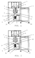
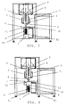
- Figures 1-8 show several moments of the operation of a system according to a preferred embodiment of the invention.
- the system comprises forming elements (2) where the film, which can come from film-feeding means (not depicted), such as for example a reel of film, passes to be applied on the forming tube (1), and then it is later driven downwards, i.e., towards the outlet end (11) of the forming tube, by means of a drive system (3) with its corresponding drive belts, for example in the same manner as in WO-A-03/086869 .
- longitudinal film-sealing means (4) which can be of any type (for example, based on conventional heated wires) and which are configured to longitudinally seal the film by means of a longitudinal seal (100) (see Figure 9 ), whereby forming a film tube (102) enveloping at least part of the forming tube (1).
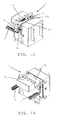
- the transverse film-sealing means (5) are configured to form successive transverse seals (101, 104) of the film tube (102) (see Figures 10 and 11 ) in a position subsequent to the outlet end (11) of the forming tube (1), i.e., under the outlet end (11).
- These transverse sealing means (5) comprise ultrasonic sealing means having opposite sealing surfaces (51, 52) made up of an anvil (51) and a sonotrode (52).
- the sonotrode (52) in turn has two sealing faces, an upper face and a lower face separated by a transverse notch along the sonotrode (52), which form two parallel weld lines upon compressing the film against the anvil (51).
- the anvil (51) is in turn made up of an upper anvil (511) facing the upper face of the sonotrode and a lower anvil (512) facing the lower face of the sonotrode as can be seen in Figure 12 .
- the lower anvil (512) of the present invention is characterized in that it has a void (513) of the order of 25 mm in length formed, for example, by means of milling which, upon forming the transverse weld (104) of the portion of film tube (10), forms a small opening (103) in the upper closure seal (104) due to the fact that the lower face of the sonotrode does not come into contact with the lower anvil (512) along said void (513).
- This opening (103) enables the subsequent extraction of the air from inside the container.
- a blade (not depicted) which cuts the film longitudinally between the two welds (101, 104), separating the film tube (102) with a longitudinal seal (100) and a lower closure seal (101) at its base, a portion (10) of film tube (102) containing the product (8) by means of a longitudinal seal (100), a transverse upper closure seal (104) which has an opening (103), and a transverse lower closure seal (101) at its base formed in a previous process, is arranged between the lower anvil (512) and the upper anvil (511), as is conventional.
- the transverse film-sealing means (5) can conventionally be activated from an electric signal generator with the suitable frequency (for example, of the order of 15-40 kHz), a converter which converts the electric signal into a mechanical signal and a booster.
- an electric signal generator with the suitable frequency (for example, of the order of 15-40 kHz)
- a converter which converts the electric signal into a mechanical signal
- booster a booster
- the longitudinal film-sealing means (4) and the transverse film-sealing means (5) are configured such that the longitudinal seal (100) is at one end of the transverse seal (101, 104).
- the longitudinal seal is formed such that two zones of one and the same surface of the film are joined together and such that these two zones are joined together close to respective longitudinal edges of the film.
- a longitudinal weld (100) is thus created in correspondence with the longitudinal edges, and there is no zone in the transverse seals (101, 104) having more than two overlapping layers of film, thus achieving a reliable transverse closure by means of ultrasonic welding both in aluminized films and in conventional films.
- stretching means (6) which are illustrated in greater detail in Figure 12 (see also Figures 15-17 ), have been provided and they comprise a clamp (61) and an expander (62) acting synchronously and configured to stretch the film tube (102) in correspondence with the sealing surfaces (51, 52) of the transverse sealing means (5) in substantially horizontal opposite directions such that the film tube (102) is substantially flat and crease-free in a direction parallel to the surfaces (51, 52) for the transverse seal.
- the clamp (61) has at least one grip (611) which seizes the film along the overlap of the longitudinal seal (100) and stretches it in the horizontal direction.
- the expander (62) is in turn joined to the inside of the forming tube (1) by means of a rotating shaft, not depicted, and comprises a stretching rod (621) protruding from under the forming tube (1), a hold-down plate (622) at its end which enters into contact with the inner surface of the film approximately at the height of the clamp (61), and a pull rod (623) acting as a lever and moving the stretching rod (621) and the hold-down plate (622) in the opposite direction as the clamp (61) when it is vertically operated by a pneumatic actuator (not depicted) arranged above the forming tube (1).
- the system for packaging additionally comprises compacting and positioning means (9) which, as shown in Figures 1-8 , comprise a compactor in a position lower than the surfaces (51, 52) for the transverse seal formed by two opposite plates (91, 92) configured to exert pressure on the film tube (102) and compact the product (8) once poured.
- compacting and positioning means 9 which, as shown in Figures 1-8 , comprise a compactor in a position lower than the surfaces (51, 52) for the transverse seal formed by two opposite plates (91, 92) configured to exert pressure on the film tube (102) and compact the product (8) once poured.
- said positioning means (9) are arranged inside the vacuum chamber (7) and comprise pneumatic actuators (93) to compact the product and pneumatic actuators (94) to vertically displace the container ( Figure 4 ) in the downward direction and introduce it inside a vacuum chamber (7), positioning said container (10) inside the vacuum chamber (7) such that the opening (103) is located exactly in the weld site of the second sealing means (77).
- the vacuum chamber (7) comprises pneumatic actuators (71) which hermetically close said chamber and a suction pump (not depicted) which extracts the air from therein until reaching a predetermined pressure. Accordingly, the air from inside the container (10) is also extracted through the opening (103), an at least partial vacuum being formed which can serve to improve conservation of the product and avoid the occurrence of creases in the surface of the container, which facilitates the work of the second sealing means (77) because the pressures inside the container (10) and inside the vacuum chamber (7) are equal at all times.
- the second sealing means (77) are then activated (as shown in Figure 7 ) by pneumatic actuators (771) which push the heat-welding jaw (772) against the film and against the anvil (773) to seal the opening (103) of the container.
- Said jaw (772) has a semicircular shape with a diameter greater than the length of the opening (103), of the order of 50 mm, and it is applied such that it circumscribes said opening (103) and overlaps with the transverse weld (104), hermetically closing the container (10) by means of a weld (105).
- the system is configured to feed the film and to form the transverse seal synchronously while feeding products through the forming tube (1), such that each product -or part of the product- to be packaged is housed in a bag defined by the film tube with a base defined by a transverse seal of the film tube.
- a product (8) to be packaged has been received on the lower closure seal (101)
- the film is fed and a new transverse seal (101, 104) is formed above the product, determining a new lower closure seal (101) at the base on which the next product to be packaged can be deposited and an upper closure seal (104) with an opening (103) in the portion of film tube (10) with product (8) therein.
- the system can work according to the following method or sequential steps:
- the film is conventionally fed and applied on the tube, a longitudinal seal or weld (100) being formed, establishing a film tube (102).
- the product (8) is fed through the forming tube (1) and a transverse seal is formed comprising the lower closure seal (101) and the upper closure seal (104) with an opening (103).
- transverse seals (101, 104) are formed with ultrasonic transverse sealing means (5) such that each portion (10) of film tube (102) is partially closed by the longitudinal seal (100) and by two transverse seals (101, 104) containing a small opening (103) through which the extraction of the air from inside the container (10) is enabled, as seen in Figures 9, 10 and 11 .
- the product (8) is introduced through the forming tube (1), as can be observed in Figure 1 .
- the transverse sealing means (5) and the stretching means (6) are in their retracted position, as are the compacting and positioning means (9), the second sealing means (77) and the vacuum chamber (7), which is open.
- the two opposite plates (91, 92) of the compacting and positioning means (9) approach one another compact and/or reorganize/reconfigure the product (8).
- the film tube (102) is also stretched through the stretching means (6), pressing the film tube (102) in opposite directions to eliminating the creases which may make the transverse sealing difficult and establishing a substantially flat surface which reduces the risk of defects in the weld.
- the surfaces of the anvil (51) and of the sonotrode (52) then approach one another and come into contact with the film tube (102) to form the transverse seal (101, 104) in the corresponding zone, leaving an opening (103) in the upper closure seal (104) of the portion (10) of the film tube (102) and forming the base (101) of the film tube (102) which will be filled with product (8) in a later process.
- the container (10) is then conventionally separated from the rest of the film tube (102) by cutting.
- the compacting and positioning means (9) then introduce the container (10) inside the vacuum chamber (7) such that the opening (103) is located exactly in the weld site of the second sealing means (77) ( Figure 4 ). Then the vacuum chamber (7) (see Figure 5 ) is hermetically closed and the air is extracted from inside the chamber (7) and from the container (10) (see Figure 6 ).
- the second sealing means (77) form a second weld (105) which closes the opening (103) and leaves the container (10) hermetically closed, as shown in Figure 7 .
- the invention is not limited to the specific embodiments that have been described, but it also encompasses, for example, the variants which can be carried out by a person skilled in the art (for example, in terms of the choice of materials, dimensions, components, configuration, etc.), within what is inferred from the claims.
Landscapes
- Engineering & Computer Science (AREA)
- Mechanical Engineering (AREA)
- Health & Medical Sciences (AREA)
- Toxicology (AREA)
- Chemical & Material Sciences (AREA)
- Dispersion Chemistry (AREA)
- Physics & Mathematics (AREA)
- Fluid Mechanics (AREA)
- Containers And Plastic Fillers For Packaging (AREA)
Claims (18)
- Système d'emballage vertical de produits, qui comprend :un tube de mise en forme (1) ;un moyen d'alimentation en film (2, 3) configuré pour appliquer un film que ledit tube de mise en forme (1), de sorte que ledit film entoure au moins une partie dudit tube de mise en forme et que ledit film soit déplacé le long d'au moins une partie dudit tube de mise en forme, vers une extrémité d'évacuation (11) dudit tube de mise en forme ;un moyen de scellage par film longitudinal (4) configuré pour sceller longitudinalement ledit film à l'aide d'un joint longitudinal (100), et pour former un tube de film (102) qui enveloppe au moins une partie dudit tube de mise en forme (1) ;un premier moyen de scellage par film transversal (5) configuré pour former un joint transversal dudit tube de film (102) à un emplacement situé après ladite extrémité d'évacuation (11) dudit tube de mise en forme (1), lesdits joints transversaux comprenant un joint de fermeture supérieur (104) et un joint de fermeture inférieur (101) ;un moyen de découpe configuré pour effectuer une découpe transversale entre ledit joint de fermeture supérieur (104) et ledit joint de fermeture inférieur (101) afin de séparer une partie (10) dudit tube de film (102) dès que ledit joint transversal a été formé ;une chambre de vide (7) configurée pour contenir ladite partie (10) dudit tube de film (102) et pour extraire l'air contenu dans ladite partie (10) jusqu'à ce qu'un vide partiel soit produit à une pression prédéterminée à l'intérieur de ladite partie (10) ;caractérisé en ce queledit premier moyen de scellage par film transversal (5) est configuré pour former un joint de fermeture supérieur (104) avec une ouverture (103), et en ce que ladite chambre de vide (7) comprend un second moyen de scellage (77) configuré pour fermer ladite ouverture (103) dès que l'air a été extrait de ladite partie (10) par le biais de ladite ouverture (103) dans ladite chambre de vide (7).
- Système selon la revendication 1, dans lequel ledit premier moyen de scellage par film transversal (5) comprend un moyen de scellage par ultrasons qui possède des surfaces de scellage opposées (51, 52) configurées pour entrer en contact avec ledit tube de film (102) et pour former ledit joint transversal, lesdites surfaces de scellage (51, 52) étant composées d'une enclume (51) et d'une sonotrode (52), ladite sonotrode comprenant une face supérieure et une face inférieure séparées par une encoche transversale afin de former ledit joint de fermeture supérieur (104) et ledit joint de fermeture inférieur (101), respectivement, ladite enclume (51) étant composée d'une enclume supérieure (511) configurée pour être tournée vers ladite face supérieure de ladite sonotrode, et d'une enclume inférieure (512) configurée pour être tournée vers ladite face inférieure de ladite sonotrode.
- Système selon la revendication 2, dans lequel ladite enclume inférieure (512) comprend un vide (513) configuré de sorte que lesdites surfaces de scellage (51, 52) ne se touchent pas le long dudit vide (513) lors de la formation dudit joint transversal, ladite ouverture (103) étant formée dans ledit joint de fermeture supérieur (104).
- Système selon la revendication 2, dans lequel ledit premier moyen de scellage par film transversal (5) comprend un moyen de poinçonnage configuré pour former ladite ouverture (103) dans ledit joint de fermeture supérieur (104).
- Système selon la revendication 1, caractérisé en ce que ledit second moyen de scellage (77) comprend une mâchoire (772) configurée pour former un joint (105) qui entoure ladite ouverture (103) et qui chevauche ledit joint de fermeture supérieur (104), en fermant hermétiquement ladite partie (10) dès que l'air a été extrait dans ladite chambre de vide (7).
- Système selon la revendication 5, caractérisé en ce que ladite mâchoire (772) possède une configuration approximativement semi-circulaire, avec un diamètre supérieur à la longueur de ladite ouverture (103).
- Système selon la revendication 1, caractérisé en ce qu'il comprend en outre un moyen de compactage et de positionnement (9) qui comprend deux plaques opposées (91, 92) placées à l'intérieur de ladite chambre de vide (7), lesdites plaques opposées (91, 92) étant configurées pour exercer une pression et compacter un produit (8) versé dans ladite partie (10) dudit tube de film (102), et pour introduire et positionner ladite partie (10) dans ladite chambre de vide (7), de sorte que ladite ouverture (103) dudit joint de fermeture supérieur (104) soit opposée audit second moyen de scellage (77).
- Système selon la revendication 1, caractérisé en ce qu'il comprend en outre un moyen d'étirement qui comprend une pince (61) et un extenseur (62) qui sont configurés pour agir de manière synchrone et pour étirer ledit tube de film (102) en correspondance avec lesdites surfaces de scellage (51, 52) dans des directions opposées sensiblement horizontales, de sorte que ledit tube de film (102) soit sensiblement plat et sans pli dans une direction parallèle auxdites surfaces (51, 52) pour ledit joint transversal.
- Système selon la revendication 8, caractérisé en ce que ladite pince (61) comprend au moins une préhension (611) configurée pour saisir ledit film le long dudit joint longitudinal (100), en ce que ledit extenseur (62) comprend une tige d'étirement (621) qui sort du dessous dudit tube de mise en forme (1), en ce que ledit extenseur comprend, à l'une de ses extrémités, une plaque de maintien (622) configurée pour toucher la surface intérieure dudit film à hauteur de ladite pince (61), et en ce que ledit extenseur (62) comprend une tige de traction (623) configurée pour déplacer ladite tige d'étirement (621) et ladite plaque de maintien (622) dans la direction opposée à ladite pince (61).
- Système selon l'une quelconque des revendications précédentes, caractérisé en ce que ledit moyen de scellage par film longitudinal (4) et ledit premier moyen de scellage par film transversal (5) sont configurés de sorte que ledit joint longitudinal (100) se trouve à une extrémité dudit joint transversal (101, 104), de sorte qu'il n'existe aucune zone dans ledit joint transversal (101, 102) qui possède plus de deux couches de film qui se chevauchent.
- Procédé d'emballage vertical de produits, qui comprend :l'application d'un film sur un tube de mise en forme (1) et la formation d'un tube de film (102) à partir dudit film à l'aide d'un joint longitudinal (100) ;l'approvisionnement séquentiel en produit (8) par le biais dudit tube de mise en forme (1) et la formation d'un joint transversal qui comprend un joint de fermeture inférieur (101) et un joint de fermeture supérieur (104) ;la réalisation d'une découpe transversale entre ledit joint de fermeture supérieur (104) et ledit joint de fermeture inférieur (101) afin de séparer une partie (10) dudit tube de film (102) avec ledit produit (8) à l'intérieur ;caractérisé en ce qu'il comprend les étapes supplémentaires qui consistent à :former une ouverture (103) dans ledit joint de fermeture supérieur (104) ;extraire l'air contenu dans ladite partie (10) dudit tube de film (102) par le biais de ladite ouverture (103) ;former un second joint (105) afin de sceller ladite ouverture (103).
- Procédé selon la revendication 11, caractérisé en ce qu'il comprend en outre l'étape qui consiste à étirer ledit tube de film (102) en correspondance avec lesdites surfaces de scellage (51, 52) avant de former ledit joint transversal avec lesdites surfaces de scellage (51, 52).
- Procédé selon la revendication 12, caractérisé en ce que ladite étape d'étirement dudit tube de film est exécutée en étirant ledit tube de film avec au moins une pince (61) et un extenseur (62) qui sont configurés pour agir de manière synchrone dans des directions opposées et sensiblement horizontales de sorte que ledit tube de film (102) soit sensiblement plat et sans pli dans une direction parallèle auxdites surfaces (51, 52) pour ledit joint transversal.
- Procédé selon la revendication 12, caractérisé en ce qu'il comprend en outre l'étape qui consiste à compacter ledit produit avec un moyen de compactage et de positionnement (9) avant de former ledit joint transversal avec lesdites surfaces de scellage (51, 52), et l'étape qui consiste à introduire et à positionner ladite partie (10) dudit tube de film (102) à l'intérieur d'une chambre de vide (7) dès que ledit joint transversal a été formé et que ladite découpe qui sépare ladite partie (10) dudit tube de film (102) a été créée, de sorte que ladite ouverture (103) soit opposée audit second moyen de scellage (77) configuré pour former ledit second joint (105) à l'intérieur de ladite chambre de vide (7).
- Procédé selon la revendication 14, caractérisé en ce que ledit second moyen de scellage (77) forme un second joint (105) à l'aide d'une mâchoire (772) qui possède une configuration approximativement semi-circulaire avec un diamètre supérieur à la longueur de ladite ouverture (103), qui entoure ladite ouverture (103) et qui chevauche ledit joint de fermeture supérieur (104), en fermant hermétiquement ladite partie (10) dudit tube de film (102).
- Procédé selon les revendications 11 à 15, caractérisé en ce que ledit joint longitudinal dudit film et ledit joint transversal dudit film sont formés de sorte que ledit joint longitudinal se trouve à une extrémité dudit joint transversal afin qu'il n'existe aucune zone au sein dudit joint transversal qui possède plus de deux couches de film qui se chevauchent.
- Procédé selon l'une quelconque des revendications 11 à 16, caractérisé en ce que ledit approvisionnement en film et ladite formation de joint transversal sont effectués de manière synchrone en fournissant lesdits produits (8) par le biais dudit tube de mise en forme (1) de sorte que chaque produit à emballer soit contenu dans une partie (10) dudit tube de film (102) avec une base définie par ledit joint de fermeture inférieur (101).
- Procédé selon la revendication 17, caractérisé en ce que ledit film est fourni après qu'un produit (8) à emballer ait été reçu sur ledit joint de fermeture inférieur (101), avant ledit joint de fermeture supérieur (104).
Applications Claiming Priority (1)
| Application Number | Priority Date | Filing Date | Title |
|---|---|---|---|
| PCT/ES2008/000556 WO2010018239A1 (fr) | 2008-08-08 | 2008-08-08 | Système et procédé d'emballage vertical |
Publications (3)
| Publication Number | Publication Date |
|---|---|
| EP2319766A1 EP2319766A1 (fr) | 2011-05-11 |
| EP2319766A4 EP2319766A4 (fr) | 2013-10-16 |
| EP2319766B1 true EP2319766B1 (fr) | 2014-04-09 |
Family
ID=41668724
Family Applications (1)
| Application Number | Title | Priority Date | Filing Date |
|---|---|---|---|
| EP08805378.0A Not-in-force EP2319766B1 (fr) | 2008-08-08 | 2008-08-08 | Système et procédé d'emballage vertical |
Country Status (3)
| Country | Link |
|---|---|
| EP (1) | EP2319766B1 (fr) |
| ES (1) | ES2462666T3 (fr) |
| WO (1) | WO2010018239A1 (fr) |
Families Citing this family (9)
| Publication number | Priority date | Publication date | Assignee | Title |
|---|---|---|---|---|
| IT1403574B1 (it) * | 2011-01-20 | 2013-10-31 | Rossi | " metodo e apparato per il confezionamento di pacchi sottovuoto " |
| DE102012004852A1 (de) * | 2011-03-17 | 2012-09-20 | Tna Australia Pty Ltd. | Former für eine Verpackungsmaschine |
| ITGE20110058A1 (it) * | 2011-05-26 | 2012-11-27 | Gianluigi Rossi | " dispositivo di saldatura dei pacchi con azionamento a doppia leva per macchine impacchettatrici " . |
| ITGE20110137A1 (it) * | 2011-11-24 | 2013-05-25 | Gianluigi Rossi | Macchina impacchettatrice sottovuoto con camera per il vuoto estraibile |
| ITGE20120016A1 (it) * | 2012-02-03 | 2013-08-04 | Gianluigi Rossi | " camera da vuoto per macchine impacchettatrici sottovuoto " |
| ITGE20120052A1 (it) * | 2012-05-17 | 2013-11-18 | Gianluigi Rossi | "dispositivo di saldatura di pacchi per macchine impacchettatrici" |
| ITVR20120242A1 (it) * | 2012-12-11 | 2014-06-12 | Vuormar Packaging S R L | Macchina e metodo di confezionamento sotto-vuoto, in particolare per il confezionamento di prodotti voluminosi e pesanti |
| ES2576694T3 (es) | 2014-02-14 | 2016-07-08 | Ulma Packaging Technological Center, S.Coop. | Método y máquina para el envasado al vacío de un producto |
| FR3019083B1 (fr) * | 2014-04-01 | 2016-12-30 | Sonimat | Dispositif de soudure par ultrasons |
Family Cites Families (8)
| Publication number | Priority date | Publication date | Assignee | Title |
|---|---|---|---|---|
| US3488915A (en) * | 1966-09-15 | 1970-01-13 | Fmc Corp | Package filling and sealing systems |
| DE2519631A1 (de) * | 1975-05-02 | 1976-11-11 | Bosch Gmbh Robert | Vorrichtung zum herstellen evakuierter packungen |
| JP3560919B2 (ja) * | 2001-02-06 | 2004-09-02 | オリヒロエンジニアリング株式会社 | 包装袋の製造方法および縦型製袋充填機 |
| US6675558B2 (en) * | 2001-04-18 | 2004-01-13 | Kraft Foods Holdings, Inc. | Method for manufacturing flexible packages having slide closures |
| WO2003026969A1 (fr) * | 2001-09-25 | 2003-04-03 | Xero Limited | Emballage de materiaux particulaires |
| US6718739B2 (en) | 2002-04-05 | 2004-04-13 | Frito-Lay North America, Inc. | Tube pack bag making |
| JP2004067177A (ja) * | 2002-08-07 | 2004-03-04 | Toyo Jidoki Co Ltd | 超音波シール装置を用いた袋の真空包装方法及び超音波シール装置を備えた真空包装機 |
| US7018099B2 (en) * | 2003-05-21 | 2006-03-28 | Cryovac, Inc. | Contoured pouch having a zigzag shape |
-
2008
- 2008-08-08 EP EP08805378.0A patent/EP2319766B1/fr not_active Not-in-force
- 2008-08-08 WO PCT/ES2008/000556 patent/WO2010018239A1/fr not_active Ceased
- 2008-08-08 ES ES08805378.0T patent/ES2462666T3/es active Active
Also Published As
| Publication number | Publication date |
|---|---|
| WO2010018239A1 (fr) | 2010-02-18 |
| ES2462666T3 (es) | 2014-05-26 |
| EP2319766A4 (fr) | 2013-10-16 |
| EP2319766A1 (fr) | 2011-05-11 |
Similar Documents
| Publication | Publication Date | Title |
|---|---|---|
| EP2319766B1 (fr) | Système et procédé d'emballage vertical | |
| US4656818A (en) | Packaging machine | |
| KR101969738B1 (ko) | 특히 음식 제품의 진공 패키징을 위한 장치 | |
| EP3000584B1 (fr) | Élément de scellage destiné au thermoscellage d'un matériau d'emballage pour produire des emballages scellés | |
| CN105705309B (zh) | 用于在用于包装灌装食品的片材包装材料上形成开口装置的设备和方法 | |
| US3423902A (en) | Production and filling of plastic containers | |
| CZ279925B6 (cs) | Tvarovací zařízení pro balicí stroje | |
| JPH06298210A (ja) | 板状包装材料ウエブから液体を充填した平行六面体の包装容器を形成する装置 | |
| EP1241100B1 (fr) | Procédé et dispositif de scellement transversal par ultrasons des parois d'un matériau d'emballage rempli d'un produit alimentaire fluide | |
| US20110269611A1 (en) | Tubular bagging method | |
| EP1733968A1 (fr) | Machine d'ensachage en particulier pour des produits granulaires et/ou pulvérulents | |
| KR101772741B1 (ko) | 초음파 용접 방법에 의해 얇은 합성수지 박막으로 튜브형 백을 제조하는 방법 및 장치 | |
| EP2998103B1 (fr) | Unité et procédé permettant d'appliquer des dispositifs d'ouverture préformés sur une bande d'un matériau d'emballage | |
| KR950002975B1 (ko) | 포장체의 제조방법과 그의 제조장치 | |
| US7815428B2 (en) | Apparatuses and processes for packaging products | |
| WO2010100751A1 (fr) | Machine d'emballage individuel | |
| AU2018267290B2 (en) | Apparatus and method for manufacturing beverage pods | |
| EP1188542B1 (fr) | Procédé et dispositif pour former un récipient à partir d'un rouleau de matière en bande | |
| EP0890516B1 (fr) | Proçédé et dispositif de thermoscellage pour la fabrication de récipients d'emballage | |
| WO2008107495A1 (fr) | Système et procédé d'emballage vertical | |
| EP4028245B1 (fr) | Unité d'étirage pour pincer et étirer un film tubulaire, enveloppeuse en continu, et procédé de pincement et d'étirage d'un film tubulaire | |
| KR102767891B1 (ko) | 포장장치 및 포장장치를 이용한 포장지 제조방법 | |
| WO2006018637A1 (fr) | Méthode et dispositif à utiliser pour l’emballage automatisé de produits | |
| JPH0236443B2 (fr) | ||
| CN114531867B (zh) | 改进的密封装置 |
Legal Events
| Date | Code | Title | Description |
|---|---|---|---|
| PUAI | Public reference made under article 153(3) epc to a published international application that has entered the european phase |
Free format text: ORIGINAL CODE: 0009012 |
|
| 17P | Request for examination filed |
Effective date: 20110221 |
|
| AK | Designated contracting states |
Kind code of ref document: A1 Designated state(s): AT BE BG CH CY CZ DE DK EE ES FI FR GB GR HR HU IE IS IT LI LT LU LV MC MT NL NO PL PT RO SE SI SK TR |
|
| AX | Request for extension of the european patent |
Extension state: AL BA MK RS |
|
| DAX | Request for extension of the european patent (deleted) | ||
| A4 | Supplementary search report drawn up and despatched |
Effective date: 20130912 |
|
| RIC1 | Information provided on ipc code assigned before grant |
Ipc: B65B 31/02 20060101ALI20130906BHEP Ipc: B65B 9/20 20120101AFI20130906BHEP |
|
| GRAP | Despatch of communication of intention to grant a patent |
Free format text: ORIGINAL CODE: EPIDOSNIGR1 |
|
| INTG | Intention to grant announced |
Effective date: 20140124 |
|
| GRAS | Grant fee paid |
Free format text: ORIGINAL CODE: EPIDOSNIGR3 |
|
| GRAA | (expected) grant |
Free format text: ORIGINAL CODE: 0009210 |
|
| AK | Designated contracting states |
Kind code of ref document: B1 Designated state(s): AT BE BG CH CY CZ DE DK EE ES FI FR GB GR HR HU IE IS IT LI LT LU LV MC MT NL NO PL PT RO SE SI SK TR |
|
| REG | Reference to a national code |
Ref country code: GB Ref legal event code: FG4D |
|
| REG | Reference to a national code |
Ref country code: CH Ref legal event code: EP Ref country code: AT Ref legal event code: REF Ref document number: 661211 Country of ref document: AT Kind code of ref document: T Effective date: 20140415 |
|
| REG | Reference to a national code |
Ref country code: IE Ref legal event code: FG4D |
|
| REG | Reference to a national code |
Ref country code: DE Ref legal event code: R096 Ref document number: 602008031433 Country of ref document: DE Effective date: 20140522 |
|
| REG | Reference to a national code |
Ref country code: ES Ref legal event code: FG2A Ref document number: 2462666 Country of ref document: ES Kind code of ref document: T3 Effective date: 20140526 |
|
| REG | Reference to a national code |
Ref country code: AT Ref legal event code: MK05 Ref document number: 661211 Country of ref document: AT Kind code of ref document: T Effective date: 20140409 |
|
| REG | Reference to a national code |
Ref country code: NL Ref legal event code: VDEP Effective date: 20140409 |
|
| REG | Reference to a national code |
Ref country code: LT Ref legal event code: MG4D |
|
| PG25 | Lapsed in a contracting state [announced via postgrant information from national office to epo] |
Ref country code: LT Free format text: LAPSE BECAUSE OF FAILURE TO SUBMIT A TRANSLATION OF THE DESCRIPTION OR TO PAY THE FEE WITHIN THE PRESCRIBED TIME-LIMIT Effective date: 20140409 Ref country code: FI Free format text: LAPSE BECAUSE OF FAILURE TO SUBMIT A TRANSLATION OF THE DESCRIPTION OR TO PAY THE FEE WITHIN THE PRESCRIBED TIME-LIMIT Effective date: 20140409 Ref country code: NO Free format text: LAPSE BECAUSE OF FAILURE TO SUBMIT A TRANSLATION OF THE DESCRIPTION OR TO PAY THE FEE WITHIN THE PRESCRIBED TIME-LIMIT Effective date: 20140709 Ref country code: BG Free format text: LAPSE BECAUSE OF FAILURE TO SUBMIT A TRANSLATION OF THE DESCRIPTION OR TO PAY THE FEE WITHIN THE PRESCRIBED TIME-LIMIT Effective date: 20140709 Ref country code: IS Free format text: LAPSE BECAUSE OF FAILURE TO SUBMIT A TRANSLATION OF THE DESCRIPTION OR TO PAY THE FEE WITHIN THE PRESCRIBED TIME-LIMIT Effective date: 20140809 Ref country code: NL Free format text: LAPSE BECAUSE OF FAILURE TO SUBMIT A TRANSLATION OF THE DESCRIPTION OR TO PAY THE FEE WITHIN THE PRESCRIBED TIME-LIMIT Effective date: 20140409 |
|
| PG25 | Lapsed in a contracting state [announced via postgrant information from national office to epo] |
Ref country code: AT Free format text: LAPSE BECAUSE OF FAILURE TO SUBMIT A TRANSLATION OF THE DESCRIPTION OR TO PAY THE FEE WITHIN THE PRESCRIBED TIME-LIMIT Effective date: 20140409 Ref country code: HR Free format text: LAPSE BECAUSE OF FAILURE TO SUBMIT A TRANSLATION OF THE DESCRIPTION OR TO PAY THE FEE WITHIN THE PRESCRIBED TIME-LIMIT Effective date: 20140409 Ref country code: PL Free format text: LAPSE BECAUSE OF FAILURE TO SUBMIT A TRANSLATION OF THE DESCRIPTION OR TO PAY THE FEE WITHIN THE PRESCRIBED TIME-LIMIT Effective date: 20140409 Ref country code: LV Free format text: LAPSE BECAUSE OF FAILURE TO SUBMIT A TRANSLATION OF THE DESCRIPTION OR TO PAY THE FEE WITHIN THE PRESCRIBED TIME-LIMIT Effective date: 20140409 Ref country code: SE Free format text: LAPSE BECAUSE OF FAILURE TO SUBMIT A TRANSLATION OF THE DESCRIPTION OR TO PAY THE FEE WITHIN THE PRESCRIBED TIME-LIMIT Effective date: 20140409 |
|
| PG25 | Lapsed in a contracting state [announced via postgrant information from national office to epo] |
Ref country code: PT Free format text: LAPSE BECAUSE OF FAILURE TO SUBMIT A TRANSLATION OF THE DESCRIPTION OR TO PAY THE FEE WITHIN THE PRESCRIBED TIME-LIMIT Effective date: 20140811 |
|
| REG | Reference to a national code |
Ref country code: DE Ref legal event code: R097 Ref document number: 602008031433 Country of ref document: DE |
|
| PG25 | Lapsed in a contracting state [announced via postgrant information from national office to epo] |
Ref country code: DK Free format text: LAPSE BECAUSE OF FAILURE TO SUBMIT A TRANSLATION OF THE DESCRIPTION OR TO PAY THE FEE WITHIN THE PRESCRIBED TIME-LIMIT Effective date: 20140409 Ref country code: RO Free format text: LAPSE BECAUSE OF FAILURE TO SUBMIT A TRANSLATION OF THE DESCRIPTION OR TO PAY THE FEE WITHIN THE PRESCRIBED TIME-LIMIT Effective date: 20140409 Ref country code: EE Free format text: LAPSE BECAUSE OF FAILURE TO SUBMIT A TRANSLATION OF THE DESCRIPTION OR TO PAY THE FEE WITHIN THE PRESCRIBED TIME-LIMIT Effective date: 20140409 Ref country code: BE Free format text: LAPSE BECAUSE OF FAILURE TO SUBMIT A TRANSLATION OF THE DESCRIPTION OR TO PAY THE FEE WITHIN THE PRESCRIBED TIME-LIMIT Effective date: 20140409 Ref country code: CZ Free format text: LAPSE BECAUSE OF FAILURE TO SUBMIT A TRANSLATION OF THE DESCRIPTION OR TO PAY THE FEE WITHIN THE PRESCRIBED TIME-LIMIT Effective date: 20140409 Ref country code: SK Free format text: LAPSE BECAUSE OF FAILURE TO SUBMIT A TRANSLATION OF THE DESCRIPTION OR TO PAY THE FEE WITHIN THE PRESCRIBED TIME-LIMIT Effective date: 20140409 |
|
| PLBE | No opposition filed within time limit |
Free format text: ORIGINAL CODE: 0009261 |
|
| STAA | Information on the status of an ep patent application or granted ep patent |
Free format text: STATUS: NO OPPOSITION FILED WITHIN TIME LIMIT |
|
| 26N | No opposition filed |
Effective date: 20150112 |
|
| PG25 | Lapsed in a contracting state [announced via postgrant information from national office to epo] |
Ref country code: LU Free format text: LAPSE BECAUSE OF FAILURE TO SUBMIT A TRANSLATION OF THE DESCRIPTION OR TO PAY THE FEE WITHIN THE PRESCRIBED TIME-LIMIT Effective date: 20140808 Ref country code: MC Free format text: LAPSE BECAUSE OF FAILURE TO SUBMIT A TRANSLATION OF THE DESCRIPTION OR TO PAY THE FEE WITHIN THE PRESCRIBED TIME-LIMIT Effective date: 20140409 Ref country code: IT Free format text: LAPSE BECAUSE OF FAILURE TO SUBMIT A TRANSLATION OF THE DESCRIPTION OR TO PAY THE FEE WITHIN THE PRESCRIBED TIME-LIMIT Effective date: 20140409 |
|
| REG | Reference to a national code |
Ref country code: CH Ref legal event code: PL |
|
| REG | Reference to a national code |
Ref country code: DE Ref legal event code: R097 Ref document number: 602008031433 Country of ref document: DE Effective date: 20150112 |
|
| PG25 | Lapsed in a contracting state [announced via postgrant information from national office to epo] |
Ref country code: LI Free format text: LAPSE BECAUSE OF NON-PAYMENT OF DUE FEES Effective date: 20140831 Ref country code: CH Free format text: LAPSE BECAUSE OF NON-PAYMENT OF DUE FEES Effective date: 20140831 |
|
| REG | Reference to a national code |
Ref country code: IE Ref legal event code: MM4A |
|
| PG25 | Lapsed in a contracting state [announced via postgrant information from national office to epo] |
Ref country code: SI Free format text: LAPSE BECAUSE OF FAILURE TO SUBMIT A TRANSLATION OF THE DESCRIPTION OR TO PAY THE FEE WITHIN THE PRESCRIBED TIME-LIMIT Effective date: 20140409 |
|
| PG25 | Lapsed in a contracting state [announced via postgrant information from national office to epo] |
Ref country code: IE Free format text: LAPSE BECAUSE OF NON-PAYMENT OF DUE FEES Effective date: 20140808 |
|
| PG25 | Lapsed in a contracting state [announced via postgrant information from national office to epo] |
Ref country code: GR Free format text: LAPSE BECAUSE OF FAILURE TO SUBMIT A TRANSLATION OF THE DESCRIPTION OR TO PAY THE FEE WITHIN THE PRESCRIBED TIME-LIMIT Effective date: 20140409 Ref country code: MT Free format text: LAPSE BECAUSE OF FAILURE TO SUBMIT A TRANSLATION OF THE DESCRIPTION OR TO PAY THE FEE WITHIN THE PRESCRIBED TIME-LIMIT Effective date: 20140409 Ref country code: CY Free format text: LAPSE BECAUSE OF FAILURE TO SUBMIT A TRANSLATION OF THE DESCRIPTION OR TO PAY THE FEE WITHIN THE PRESCRIBED TIME-LIMIT Effective date: 20140409 |
|
| PG25 | Lapsed in a contracting state [announced via postgrant information from national office to epo] |
Ref country code: TR Free format text: LAPSE BECAUSE OF FAILURE TO SUBMIT A TRANSLATION OF THE DESCRIPTION OR TO PAY THE FEE WITHIN THE PRESCRIBED TIME-LIMIT Effective date: 20140409 Ref country code: HU Free format text: LAPSE BECAUSE OF FAILURE TO SUBMIT A TRANSLATION OF THE DESCRIPTION OR TO PAY THE FEE WITHIN THE PRESCRIBED TIME-LIMIT; INVALID AB INITIO Effective date: 20080808 |
|
| REG | Reference to a national code |
Ref country code: FR Ref legal event code: PLFP Year of fee payment: 9 |
|
| REG | Reference to a national code |
Ref country code: FR Ref legal event code: PLFP Year of fee payment: 10 |
|
| PGFP | Annual fee paid to national office [announced via postgrant information from national office to epo] |
Ref country code: FR Payment date: 20170825 Year of fee payment: 10 Ref country code: ES Payment date: 20170918 Year of fee payment: 10 Ref country code: DE Payment date: 20170829 Year of fee payment: 10 Ref country code: GB Payment date: 20170829 Year of fee payment: 10 |
|
| REG | Reference to a national code |
Ref country code: DE Ref legal event code: R119 Ref document number: 602008031433 Country of ref document: DE |
|
| GBPC | Gb: european patent ceased through non-payment of renewal fee |
Effective date: 20180808 |
|
| PG25 | Lapsed in a contracting state [announced via postgrant information from national office to epo] |
Ref country code: DE Free format text: LAPSE BECAUSE OF NON-PAYMENT OF DUE FEES Effective date: 20190301 |
|
| PG25 | Lapsed in a contracting state [announced via postgrant information from national office to epo] |
Ref country code: FR Free format text: LAPSE BECAUSE OF NON-PAYMENT OF DUE FEES Effective date: 20180831 |
|
| REG | Reference to a national code |
Ref country code: ES Ref legal event code: FD2A Effective date: 20190918 |
|
| PG25 | Lapsed in a contracting state [announced via postgrant information from national office to epo] |
Ref country code: GB Free format text: LAPSE BECAUSE OF NON-PAYMENT OF DUE FEES Effective date: 20180808 Ref country code: ES Free format text: LAPSE BECAUSE OF NON-PAYMENT OF DUE FEES Effective date: 20180809 |