EP2319952B1 - Procédé et système pour déposer plusieurs matériaux sur un substrat - Google Patents
Procédé et système pour déposer plusieurs matériaux sur un substrat Download PDFInfo
- Publication number
- EP2319952B1 EP2319952B1 EP10188681.0A EP10188681A EP2319952B1 EP 2319952 B1 EP2319952 B1 EP 2319952B1 EP 10188681 A EP10188681 A EP 10188681A EP 2319952 B1 EP2319952 B1 EP 2319952B1
- Authority
- EP
- European Patent Office
- Prior art keywords
- materials
- recesses
- substrate
- deposition
- sublimation
- Prior art date
- Legal status (The legal status is an assumption and is not a legal conclusion. Google has not performed a legal analysis and makes no representation as to the accuracy of the status listed.)
- Active
Links
Images


Classifications
-
- C—CHEMISTRY; METALLURGY
- C23—COATING METALLIC MATERIAL; COATING MATERIAL WITH METALLIC MATERIAL; CHEMICAL SURFACE TREATMENT; DIFFUSION TREATMENT OF METALLIC MATERIAL; COATING BY VACUUM EVAPORATION, BY SPUTTERING, BY ION IMPLANTATION OR BY CHEMICAL VAPOUR DEPOSITION, IN GENERAL; INHIBITING CORROSION OF METALLIC MATERIAL OR INCRUSTATION IN GENERAL
- C23C—COATING METALLIC MATERIAL; COATING MATERIAL WITH METALLIC MATERIAL; SURFACE TREATMENT OF METALLIC MATERIAL BY DIFFUSION INTO THE SURFACE, BY CHEMICAL CONVERSION OR SUBSTITUTION; COATING BY VACUUM EVAPORATION, BY SPUTTERING, BY ION IMPLANTATION OR BY CHEMICAL VAPOUR DEPOSITION, IN GENERAL
- C23C14/00—Coating by vacuum evaporation, by sputtering or by ion implantation of the coating forming material
- C23C14/22—Coating by vacuum evaporation, by sputtering or by ion implantation of the coating forming material characterised by the process of coating
- C23C14/24—Vacuum evaporation
- C23C14/243—Crucibles for source material
-
- C—CHEMISTRY; METALLURGY
- C23—COATING METALLIC MATERIAL; COATING MATERIAL WITH METALLIC MATERIAL; CHEMICAL SURFACE TREATMENT; DIFFUSION TREATMENT OF METALLIC MATERIAL; COATING BY VACUUM EVAPORATION, BY SPUTTERING, BY ION IMPLANTATION OR BY CHEMICAL VAPOUR DEPOSITION, IN GENERAL; INHIBITING CORROSION OF METALLIC MATERIAL OR INCRUSTATION IN GENERAL
- C23C—COATING METALLIC MATERIAL; COATING MATERIAL WITH METALLIC MATERIAL; SURFACE TREATMENT OF METALLIC MATERIAL BY DIFFUSION INTO THE SURFACE, BY CHEMICAL CONVERSION OR SUBSTITUTION; COATING BY VACUUM EVAPORATION, BY SPUTTERING, BY ION IMPLANTATION OR BY CHEMICAL VAPOUR DEPOSITION, IN GENERAL
- C23C14/00—Coating by vacuum evaporation, by sputtering or by ion implantation of the coating forming material
- C23C14/22—Coating by vacuum evaporation, by sputtering or by ion implantation of the coating forming material characterised by the process of coating
- C23C14/228—Gas flow assisted PVD deposition
-
- C—CHEMISTRY; METALLURGY
- C23—COATING METALLIC MATERIAL; COATING MATERIAL WITH METALLIC MATERIAL; CHEMICAL SURFACE TREATMENT; DIFFUSION TREATMENT OF METALLIC MATERIAL; COATING BY VACUUM EVAPORATION, BY SPUTTERING, BY ION IMPLANTATION OR BY CHEMICAL VAPOUR DEPOSITION, IN GENERAL; INHIBITING CORROSION OF METALLIC MATERIAL OR INCRUSTATION IN GENERAL
- C23C—COATING METALLIC MATERIAL; COATING MATERIAL WITH METALLIC MATERIAL; SURFACE TREATMENT OF METALLIC MATERIAL BY DIFFUSION INTO THE SURFACE, BY CHEMICAL CONVERSION OR SUBSTITUTION; COATING BY VACUUM EVAPORATION, BY SPUTTERING, BY ION IMPLANTATION OR BY CHEMICAL VAPOUR DEPOSITION, IN GENERAL
- C23C14/00—Coating by vacuum evaporation, by sputtering or by ion implantation of the coating forming material
- C23C14/22—Coating by vacuum evaporation, by sputtering or by ion implantation of the coating forming material characterised by the process of coating
- C23C14/24—Vacuum evaporation
- C23C14/26—Vacuum evaporation by resistance or inductive heating of the source
Definitions
- This invention relates generally to methods and systems for depositing multiple materials on a substrate. More particularly, this invention relates to methods and systems for deposition of multiple materials on a substrate using co-sublimation processes for solar or photovoltaic cells.
- Photovoltaic systems are used for converting solar energy into electrical energy. Power production by photovoltaic systems may offer a number of advantages over conventional systems, including low operating costs, high reliability, modularity, low construction costs, and environmental benefits.
- the thin film solar cells have the potential to lower costs since such cells require significantly smaller amounts of semiconductor materials relative to conventional photovoltaic modules to produce a comparable amount of power.
- some thin film solar cells employ cadmium telluride (CdTe) films because CdTe has a direct bandgap of 1.5eV and can improve solar conversion efficiency of such solar cells.
- CdTe cadmium telluride
- dopants may be introduced in the CdTe films.
- conventional processes such as conventional close spaced sublimation (CSS) and vapor transport (VTM) processes are not suited to codepositing CdTe with other materials, due to the different melting points and vapor pressures of the materials.
- One process that has been shown to co-deposit CdTe with other materials is co-evaporation.
- co-evaporation processes are inherently time-consuming and may not be suitable for co-deposition of CdTe and certain other materials for photovoltaic applications.
- US 2004/040504 discloses an evaporation apparatus for film formation.
- US 2009/173279 relates to a vacuum vapor deposition apparatus.
- FIG. 1 illustrates a schematic diagram of a deposition system 10 configured to deposit two or more different materials on a substrate 100.
- the materials may be deposited on the substrate 100 for formation of solar or photovoltaic cells.
- the deposition system 10 may be used for manufacturing other devices.
- the substrate 100 comprises a glass layer (not shown) with a transparent conducting oxide (TCO) layer deposited on the glass layer.
- TCO transparent conducting oxide
- the glass layer include borosilicate glass, low-alkaline glass, soda-lime glass, low-iron galss, and similar materials.
- the TCO layer include tin oxide and indium tin oxide.
- the substrate 100 may comprise a polymer layer with a metal layer deposited on the polymer layer.
- the polymer layer may comprise polyimide and the metal layer may comprise molybdenum.
- the substrate 100 may comprise other suitable materials, for example, a stainless steel layer with a molybdenum layer deposited on the stainless steel layer.
- the system 10 comprises a susceptor 11 defining a plurality of recesses 12.
- the recesses 12 extend down from an upper surface 110 of the susceptor 11 and are spatially separated from each other for accommodating a first material 13 and a second material 14.
- the first and second materials 13, 14 are disposed alternately on the susceptor 11.
- the susceptor 11 may be formed of thermally conductive materials.
- thermal conductive materials include graphite, tungsten, silicon carbide (SiC) coated graphite, and high temperature metals and alloys, such as stainless steel and alloy steel.
- the first and second materials 13, 14 may comprise cadmium telluride (CdTe), tellurium (Te), zinc tellurium (ZnTe), arsenic (As), cadmium chloride (CdCl 2 ), cadmium sulfide (CdS), other materials containing dopants to CdTe, and combinations thereof.
- Non-limiting examples of the dopants may include silver (Ag), copper (Cu), gold (Au), bismuth (Bi), antimony (Sb), arsenic (As), phosphor (P), and nitrogen (N).
- the first material 13 comprises cadmium telluride (CdTe) and is different from the second material 14.
- FIGS. 1-11 are merely illustrative.
- the same numerals in FIGS. 1-11 may indicate similar elements.
- more than one susceptor 11 may be employed and/or more than two materials may be accommodated into the respective recesses 12 for deposition on the substrate 100.
- each of the recesses 12 may be in the form of cell, so that, as illustrated in FIG. 2 , a plurality of spatially separated cells 12 may be arranged as a matrix on the susceptor 11 so as to form two or more cell columns.
- each cell may have a rectangular or a cylindrical shape, and the cells in the same column may be used to receive the same material.
- each of the recesses 12 may be in the form of trench, so that, as illustrated in FIG. 3 , a plurality of trenches 12 may be distributed on the susceptor 11 to accommodate the respective first and second materials, which may be disposed alternately.
- each trench may have a rectangular or an arc shaped cross-section.
- the system 10 further comprises one or more heaters, such as a resistive heater 21 shown in FIG. 5 for heating the susceptor 11.
- a resistive heater 21 shown in FIG. 5 for heating the susceptor 11.
- other suitable heaters including, without limitation, halogen lamps and radio frequency heaters, which may be easily implemented by one skilled in the art.
- the one or more heaters heat the susceptor 11, so that the first and second materials 13, 14 in the respective recesses 12 are heated to a certain temperature to sublimate simultaneously. Then, the two sublimated gases mix together during transmission towards the substrate 100 so as to deposit on the substrate 100 in the form of film, which is referred to as a co-sublimation process.
- first and second materials 13, 14 in the recesses 12 may be heated to the same temperature. In other examples, the first material 13 and the second material 14 may be heated to different temperatures.
- the substrate 100 may be stationary relative to the susceptor(s) 11. Alternatively, the substrate 100 may move relative to the susceptor(s) 11. The substrate 100 may be preheated to a lower temperature than the respective heated temperatures of the first and second materials 13, 14.
- the geometry may differ for the respective recesses 12 for receiving the two materials.
- the recesses 12 having larger depths receive more thermal energy than the recesses with shallower depths, due to the thermal gradient. In this manner, the first and second materials are heated to different temperatures.
- the thermal conductivity for a subset of the recesses may be enhanced relative to that of the other recesses.
- the system 10 may employ one or more materials disposed on periphery of and/or into the respective recesses 12 so as to react to, for example absorb more thermal energy from the one or more heaters.
- one or more heat absorbing materials such as titanium, may be disposed around the recesses 12 accommodating the first material 13, so that the first material 13 is heated to a higher temperature than the second material 14 for sublimation.
- the system 10 further employs a plurality of lids 15 disposed on respective ones of the recesses 12 for accommodating the second material 14.
- Each lid 15 defines an opening 16 that is in fluid communication with the recess 12.
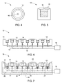
- FIGS. 4 and 5 illustrate a top view and a cross sectional view of one recess with one lid disposed thereon.
- the recess 12 has a cylindrical shape and the opening 16 is in fluid communication with the recess 12, so that, during the sublimation process, the dimension of the opening 16 may be adjusted via moving the lid 15 so as to adjust the sublimated vapor pressure of the second material 14.
- the lids 15 may or may not be disposed on the first material recesses 12.
- the system 10 may employ one or more thermal monitoring devices to monitor the temperatures of the recesses 12.
- a plurality of first and second thermocouples 17 and 18 extend into the susceptor 11 and are disposed below the recesses 12 to detect the temperatures thereon so as to monitor the temperatures of the first and second materials 13, 14.
- the recesses 12 for accommodating the first and second materials may be heated to the same temperature.
- the recesses 12 accommodating the first material and/or the second material are heated to different temperatures.
- first and second thermocouples 17 and 18 may be connected to a monitoring device 19 to monitor the temperature of each recess 12. In other examples, two or more monitoring devices may be used. Additionally, in some examples, the monitoring device(s) may be operatively connected to heater(s) to provide feedback for thermal control.
- thermal insulation may be disposed on the susceptor 11.
- one or more thermal insulation layers may be provided to better thermally isolate respective ones of the recesses from neighboring recesses.
- FIG. 7 is a schematic diagram of the system 10 employing a plurality of thermal insulation layers 20.
- the system 10 comprises a plurality of recesses 12 defined on a susceptor 11 for accommodating the first and second materials 13, 14.
- the thermal insulation layers 20 are disposed at two ends of the susceptor 11 and between every two adjacent recesses 12 for thermal insulation.
- Non-limiting examples of the thermal insulation include polystyrene, polyurethane, polystyrene foam, and ceramic materials.
- the thermal insulation layer 20 is further disposed on a bottom surface (not labeled) of the susceptor 11 to reduce thermal convection via the bottom surface of the susceptor 11. In other examples, thermal insulation is not employed on the bottom surface of the susceptor 11.
- the system 10 further comprises a plurality of lids 15 disposed on the recesses 12 for accommodating the second material 14 and a resistive heater 21 for heating the respective recesses 12.
- one or more lids 15 may or may not be disposed on the one or more recesses 12 for accommodating the first material 13.
- the resistive heater 21 comprises a coil 23.
- the coil 23 is disposed around each of the recesses 12.
- the system 10 further comprises a power source 22 provided for the coil 23 and configured to pass an electrical current through the coil 23 to heat the recesses 12.
- the coil 23 has more turns on the recesses 12 receiving the first material 13 than those on the recesses 12 receiving the second material 14. In this manner, the first material 13 and the second material 14 are heated separately and the first material 13 may be heated to a higher temperature than the second material 14.
- the example system 10 shown in FIG. 7 also employs a plurality of first and second thermocouples 17 and 18 configured to monitor the temperatures of the first and second materials 13, 14 respectively.
- one or more monitoring devices 19 may also be operatively connected to the first and second thermocouples 17 and 18, and may further be operatively connected to the heater 21 to provide feedback for thermal control.
- FIG. 8 is a schematic diagram of the system 10 having a plurality of spatially separated susceptors.
- the system 10 comprises a plurality of spatially separated susceptors 11 for accommodating the first and second materials, and a deposition device 24 defining a sublimation zone 25 with a lower opening 26.
- the spatially separated susceptors 11 are disposed within the sublimation zone 25.
- a substrate 100 is disposed below the deposition device 24.
- the system 10 may comprise one or more heaters for heating the susceptors 11.
- the heater(s) may be disposed outside the deposition device 24. In other examples, the heater(s) may be disposed within the sublimation zone 25, and/or within an upper wall 50 and/or sidewalls 51 of the deposition device 23 for heating the susceptors 11.
- the first and second materials 13, 14 sublime at a certain temperature. Since the temperature of the deposition device 24 is higher than the temperatures to which the first and second materials 13, 14 are heated, the sublimated gases of the first and second materials 13, 14 are not deposited on the inner surfaces of the deposition device 24 and are transmitted in a downward direction for deposition on the substrate 100, as indicated by the dashed arrows.
- the system 10 further comprises a diffusion element 28 for diffusion and thus more uniform distribution of the sublimated gases on the substrate 100.
- a diffusion element 28 for diffusion and thus more uniform distribution of the sublimated gases on the substrate 100.
- more than one diffusion element 28 may be employed.
- the temperature of the diffusion element(s) 28 may also be higher than the temperatures to which the first and second materials are heated, so that the sublimated gases are deposited on the substrate 100 and not on diffusion element(s) 28.
- the substrate 100 is disposed below the deposition device 24. More than two spatially separated susceptors 11 are employed and each susceptor 11 defines a recess 12. In other examples, the substrate 100 may also be disposed within the sublimation zone 25 and between the upper wall 50 and the susceptors 11.
- the system 10 may employ two susceptors, and each susceptor 11 may define more than one recess 12.
- the system 10 may also employ a deposition device to accommodate the susceptor(s) 11, which may be similar to the deposition device 24 shown in FIG. 8 , but may define an upper opening, so that the substrate 100 is disposed above the susceptor(s) 11 for deposition.
- a deposition device to accommodate the susceptor(s) 11, which may be similar to the deposition device 24 shown in FIG. 8 , but may define an upper opening, so that the substrate 100 is disposed above the susceptor(s) 11 for deposition.
- One or more diffusion elements similar to the diffusion element 28 shown in FIG. 8 may also be disposed between the substrate 100 and the susceptor(s) 11.
- sublimation and deposition processes may be performed in a variety of environments, for example, in an ambient environment or in the presence of a gas, such as oxygen, hydrogen, nitrogen, chlorine, an inert gas, and combinations thereof.
- a gas such as oxygen, hydrogen, nitrogen, chlorine, an inert gas, and combinations thereof.
- inert gases include argon and helium.
- FIG. 9 is a schematic diagram of another configuration of the system 10.
- the system 10 comprises a deposition device 30 defining a sublimation zone 31 and two susceptors 11 both disposed within first and second sublimation zones 52, 53 of the sublimation zone 31.
- the sublimation device 30 further defines an inlet 32, an inlet passage 34, an outlet 33, and an outlet passage 35 in fluid communication with the sublimation zone 31.
- a substrate 100 faces the outlet 33.
- the system 10 further comprises a carrier gas source (not shown) and one or more heaters (not shown).
- the carrier gas source is configured to supply a carrier gas into the sublimation zone 31 through the inlet 32 and the inlet passage 34.
- the one or more heaters are configured to heat and sublimate the first and second materials 13, 14, and may be disposed outside of the sublimation device 30, around the susceptors 11 and/or within one or more walls (not labeled) defining the sublimation zone 31.
- the one or more heaters heat the susceptors 11 to sublimate the first and second materials 13, 14.
- the first and second materials are heated to different temperatures for sublimation.
- the carrier gas source supplies a carrier gas 36 into the sublimation zone 31 to carry the sublimated gases out of the sublimation zone 31 through the outlet passage 35 and the outlet 32.
- the first and the second materials are continuously deposited on the substrate 100 while the substrate 100 moves along a direction 37, which is opposite to the direction 38 of the depleted carrier gas.
- the outlet passage 35 While moving toward the outlet 33, the sublimated gases are mixed in the outlet passage 35, which thus acts as a mixing zone, and thereby improves the quality of the deposition on the substrate 100.
- the outlet passage 35 may not be employed.
- the carrier gas 36 may be saturated with the sublimated gases of the first and second materials 13, 14 to facilitate deposition on the substrate 100.
- the substrate 100 may move in the same direction as the depleted carrier gas or may be stationary.
- temperatures of the sublimation device 30 and the substrate 100 may be higher and lower than the heated temperatures of the first and second materials 13, 14, respectively, to facilitate deposition of the first and second materials on the substrate 100.
- the carrier gas may first carry the sublimated gas of the material that sublimes at a lower temperature.
- the carrier gas then carries the sublimated gas of the material that sublimes at a higher temperature.
- the carrier gas first carries the sublimated gas of the second material and then carries the sublimated gas of the first material if the second material sublimes at a lower temperature than the first material.
- the carrier gas may pass by all of the susceptors accommodating the second materials, and then pass by all of the susceptors accommodating the first material.
- the system 10 may or may not comprise one or more lids 15 disposed on respective ones of the one or two susceptors 11.
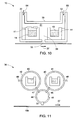
- FIG. 10 is a schematic diagram of illustrating a configuration of the system 10 with two inlets 31.
- the arrangement in FIG. 10 is similar to the arrangement shown in FIG. 9 .
- the two arrangements differ in that the system 10 illustrated in FIG. 10 comprises two inlets 32, and an outlet 33 is disposed between the two susceptors 11.
- first and second carrier gases 54, 55 pass into the sublimation zone 31 from the inlets 32 to carry the respective sublimated gases of the first and second materials. Then, the sublimated gases are mixed in a mixing zone 39 defined between the two susceptors 11 and pass out of the sublimation zone 31 for deposition on the moving substrate 100.
- first and second carrier gases 54, 55 may be the same or different gases.
- Non-limiting examples of the first and second carrier gases include inert gases, such as argon and helium.
- the mixing zone and the sublimation zone 31 overlap spatially.
- the first and second sublimation zones also spatially overlap.
- the mixing zone may be spatially separated from the sublimation zone 31.
- the first and second sublimation zones may also be spatially separated from each other.
- a deposition device 30 comprises a first deposition element 40 defining a first sublimation zone 41, a second deposition element 42 defining a second sublimation zone 43, and a mixing element 44 defining a mixing zone 45.
- First and second passageways 46, 47 provide fluid connections between the mixing zone and the respective first and second sublimation zones 41, 43.
- a first inlet 48 and a second inlet 49 are disposed on the first and second elements 40, 42 to be in fluid communication with the respective sublimation zones 41, 43, through which first and second carrier gases pass into the sublimation zones 41, 43 to carry the respective sublimated gases.
- first sublimation zone 41, the second sublimation zone 43 and the mixing zone 45 are spatially separated from each other. Accordingly, in operation, the first and second materials are sublimated in the respective sublimation zone 41, 43. Then, first and second carrier gases (not shown) carry the respective sublimated gases into the mixing zone 45 through the respective passageways 48, 49 for mixing. Subsequently, the mixed sublimated gases pass out of the mixing zone from an outlet 33 for deposition on the moving substrate 100.
- the substrate 100 may be stationary.
- the first and second carrier gases may also be saturated with the sublimated gases of the first and second materials 13, 14 to facilitate subsequent deposition on the substrate 100.
- more than two deposition elements and/or more than two susceptors may be employed.
- One or more lids may or may not be employed on respective ones of the susceptors to adjust the pressures of the one or more sublimated gases.
- the vapor pressure of the one or more sublimated gases in the mixing zone 45 may be adjusted by changing the gas flow resistivity of one or more of the passageways 48, 49.
Landscapes
- Chemical & Material Sciences (AREA)
- Chemical Kinetics & Catalysis (AREA)
- Engineering & Computer Science (AREA)
- Materials Engineering (AREA)
- Mechanical Engineering (AREA)
- Metallurgy (AREA)
- Organic Chemistry (AREA)
- Physical Vapour Deposition (AREA)
- Chemical Vapour Deposition (AREA)
Claims (7)
- Système (10) de dépôt de deux matières ou plus sur un substrat (100), le système (10) comprenant :un ou plusieurs suscepteurs (11) configurés pour définir deux évidements (12) ou plus pour loger au moins une première matière (13) et une seconde matière (14) différente de la première matière (13) respectivement ; etun ou plusieurs éléments chauffants destinés à chauffer la première matière (13) et la seconde matière (14) pour les sublimer en vue d'un dépôt sur le substrat (100) ; caractérisé en ce que :chacun des un ou plusieurs éléments chauffants comprend un élément chauffant résistif (21), dans lequel l'élément chauffant résistif (21) comprend une bobine (23) disposée autour d'un ou plusieurs des évidements (12), dans lequel le système (10) comprend en outre une source d'alimentation (22) configurée pour faire passer un courant électrique à travers la bobine (23) pour chauffer une ou plusieurs des première et seconde matières (13, 14), et dans lequel la bobine (23) disposée autour de l'évidement (12) logeant la première matière (13) comporte davantage de spires que la bobine (23) disposée autour de l'évidement (12) logeant la seconde matière (14).
- Système selon la revendication 1, dans lequel chacun des un ou plusieurs suscepteurs (11) définit les deux évidements (12) ou plus.
- Système selon l'une quelconque des revendications précédentes, dans lequel la première matière (13) et la seconde matière (14) sont chauffées séparément à des températures différentes.
- Système selon l'une quelconque des revendications précédentes, comprenant en outre un ou plusieurs couvercles (15) disposés de façon mobile sur des évidements respectifs parmi les évidements (12) et configurés pour ajuster la pression de vapeur d'une ou plusieurs des première et seconde matières évaporées.
- Procédé de dépôt de deux matières ou plus sur un substrat (100) faisant appel au système (10) de l'une quelconque des revendications précédentes, le procédé comprenant :la fourniture d'un ou plusieurs suscepteurs (11) configurés pour définir deux évidements (12) ou plus pour loger une première matière (13) et une seconde matière (14) différente de la première matière (13) respectivement ; etle fait de chauffer la première matière (13) et la seconde matière (14) pour une sublimation de la première matière (13) et de la seconde matière (14) en vue d'un dépôt sur le substrat (100).
- Procédé selon la revendication 5, comprenant en outre le dépôt en alternance de la première matière (13) et de la seconde matière (14) sur les évidements respectifs (12), et dans lequel chacun des un ou plusieurs suscepteurs (11) définit les deux évidements (12) ou plus.
- Procédé selon la revendication 5 ou la revendication 6, dans lequel la première matière (13) et la seconde matière (14) sont chauffées séparément à des températures différentes.
Applications Claiming Priority (1)
| Application Number | Priority Date | Filing Date | Title |
|---|---|---|---|
| US12/608,455 US20110104398A1 (en) | 2009-10-29 | 2009-10-29 | Method and system for depositing multiple materials on a substrate |
Publications (2)
| Publication Number | Publication Date |
|---|---|
| EP2319952A1 EP2319952A1 (fr) | 2011-05-11 |
| EP2319952B1 true EP2319952B1 (fr) | 2014-12-03 |
Family
ID=43566679
Family Applications (1)
| Application Number | Title | Priority Date | Filing Date |
|---|---|---|---|
| EP10188681.0A Active EP2319952B1 (fr) | 2009-10-29 | 2010-10-25 | Procédé et système pour déposer plusieurs matériaux sur un substrat |
Country Status (4)
| Country | Link |
|---|---|
| US (1) | US20110104398A1 (fr) |
| EP (1) | EP2319952B1 (fr) |
| CN (1) | CN102051599B (fr) |
| AU (1) | AU2010235906A1 (fr) |
Families Citing this family (9)
| Publication number | Priority date | Publication date | Assignee | Title |
|---|---|---|---|---|
| KR20130010730A (ko) * | 2011-07-19 | 2013-01-29 | 삼성디스플레이 주식회사 | 증착 소스 및 이를 구비한 증착 장치 |
| US8778081B2 (en) * | 2012-01-04 | 2014-07-15 | Colorado State University Research Foundation | Process and hardware for deposition of complex thin-film alloys over large areas |
| KR102007697B1 (ko) * | 2013-02-28 | 2019-08-06 | 삼성에스디아이 주식회사 | 이차전지용 전극 제조 장치 |
| CN104213078A (zh) * | 2013-05-30 | 2014-12-17 | 海洋王照明科技股份有限公司 | 一种低浓度掺杂的蒸发设备 |
| CN104178734B (zh) * | 2014-07-21 | 2016-06-15 | 京东方科技集团股份有限公司 | 蒸发镀膜装置 |
| CN105132868B (zh) * | 2015-09-25 | 2019-09-27 | 京东方科技集团股份有限公司 | 蒸发源及其制作方法、蒸镀方法 |
| TWI606132B (zh) * | 2016-01-27 | 2017-11-21 | 國立清華大學 | 有機發光元件之有機層的製作方法 |
| US20180166300A1 (en) * | 2016-12-13 | 2018-06-14 | Lam Research Ag | Point-of-use mixing systems and methods for controlling temperatures of liquids dispensed at a substrate |
| CN110021715B (zh) * | 2018-01-09 | 2021-12-28 | 鸿富锦精密工业(深圳)有限公司 | 蒸镀源及有机发光二极管显示面板的制造方法 |
Family Cites Families (24)
| Publication number | Priority date | Publication date | Assignee | Title |
|---|---|---|---|---|
| US2724663A (en) * | 1952-10-23 | 1955-11-22 | Bell Telephone Labor Inc | Plural metal vapor coating |
| US3858548A (en) * | 1972-08-16 | 1975-01-07 | Corning Glass Works | Vapor transport film deposition apparatus |
| JPS53110973A (en) * | 1977-03-10 | 1978-09-28 | Futaba Denshi Kogyo Kk | Method and apparatus for manufacturing compounds |
| JPS59156996A (ja) * | 1983-02-23 | 1984-09-06 | Koito Mfg Co Ltd | 化合物結晶膜の製造方法とその装置 |
| KR930007853B1 (ko) * | 1986-12-10 | 1993-08-20 | 후지 세이끼 가부시기 가이샤 | 진공 증발장치 |
| DE4132882C2 (de) * | 1991-10-03 | 1996-05-09 | Antec Angewandte Neue Technolo | Verfahren zur Herstellung von pn CdTe/CdS-Dünnschichtsolarzellen |
| US5336324A (en) * | 1991-12-04 | 1994-08-09 | Emcore Corporation | Apparatus for depositing a coating on a substrate |
| US5366764A (en) * | 1992-06-15 | 1994-11-22 | Sunthankar Mandar B | Environmentally safe methods and apparatus for depositing and/or reclaiming a metal or semi-conductor material using sublimation |
| US5253266A (en) * | 1992-07-20 | 1993-10-12 | Intevac, Inc. | MBE effusion source with asymmetrical heaters |
| JP3779373B2 (ja) * | 1996-04-22 | 2006-05-24 | 株式会社ムサシノエンジニアリング | 真空蒸着装置 |
| US5994642A (en) * | 1996-05-28 | 1999-11-30 | Matsushita Battery Industrial Co., Ltd. | Method for preparing CdTe film and solar cell using the same |
| ATE374263T1 (de) * | 1999-03-29 | 2007-10-15 | Antec Solar Energy Ag | Vorrichtung und verfahren zur beschichtung von substraten durch aufdampfen mittels eines pvd- verfahrens |
| US6237529B1 (en) * | 2000-03-03 | 2001-05-29 | Eastman Kodak Company | Source for thermal physical vapor deposition of organic electroluminescent layers |
| US7194197B1 (en) * | 2000-03-16 | 2007-03-20 | Global Solar Energy, Inc. | Nozzle-based, vapor-phase, plume delivery structure for use in production of thin-film deposition layer |
| US6423565B1 (en) * | 2000-05-30 | 2002-07-23 | Kurt L. Barth | Apparatus and processes for the massproduction of photovotaic modules |
| CN101397649B (zh) * | 2001-02-01 | 2011-12-28 | 株式会社半导体能源研究所 | 能够将有机化合物沉积在衬底上的装置 |
| US20040040504A1 (en) * | 2002-08-01 | 2004-03-04 | Semiconductor Energy Laboratory Co., Ltd. | Manufacturing apparatus |
| JP2004095330A (ja) * | 2002-08-30 | 2004-03-25 | Tohoku Pioneer Corp | 電子部品を覆う保護膜の形成方法および保護膜を備えた電子機器 |
| JP4015064B2 (ja) * | 2003-05-28 | 2007-11-28 | トッキ株式会社 | 蒸着装置 |
| US20050175770A1 (en) * | 2004-02-10 | 2005-08-11 | Eastman Kodak Company | Fabricating an electrode for use in organic electronic devices |
| JP2006057173A (ja) * | 2004-08-24 | 2006-03-02 | Tohoku Pioneer Corp | 成膜源、真空成膜装置、有機elパネルの製造方法 |
| JP2006225757A (ja) * | 2005-01-21 | 2006-08-31 | Mitsubishi Heavy Ind Ltd | 真空蒸着装置 |
| JP2008297610A (ja) * | 2007-05-31 | 2008-12-11 | Fujifilm Corp | 真空蒸着方法 |
| US20090162535A1 (en) * | 2007-12-21 | 2009-06-25 | Jean-Pierre Tahon | Method of forming a phosphor or scintillator material and vapor deposition apparatus used therefor |
-
2009
- 2009-10-29 US US12/608,455 patent/US20110104398A1/en not_active Abandoned
-
2010
- 2010-10-19 AU AU2010235906A patent/AU2010235906A1/en not_active Abandoned
- 2010-10-25 EP EP10188681.0A patent/EP2319952B1/fr active Active
- 2010-10-29 CN CN201010538504.0A patent/CN102051599B/zh active Active
Also Published As
| Publication number | Publication date |
|---|---|
| AU2010235906A1 (en) | 2011-05-19 |
| EP2319952A1 (fr) | 2011-05-11 |
| CN102051599A (zh) | 2011-05-11 |
| US20110104398A1 (en) | 2011-05-05 |
| CN102051599B (zh) | 2015-04-29 |
Similar Documents
| Publication | Publication Date | Title |
|---|---|---|
| EP2319952B1 (fr) | Procédé et système pour déposer plusieurs matériaux sur un substrat | |
| US7585547B2 (en) | Method and apparatus to form thin layers of materials on a base | |
| EP1938360B1 (fr) | Procede et appareil permettant de convertir des couches de precurseurs en absorbeurs photovoltaiques | |
| CN101061588B (zh) | 在箔衬底上太阳能电池的形成 | |
| US20080175993A1 (en) | Reel-to-reel reaction of a precursor film to form solar cell absorber | |
| US9196768B2 (en) | Method and apparatus for depositing copper—indium—gallium selenide (CuInGaSe2-CIGS) thin films and other materials on a substrate | |
| US8323408B2 (en) | Methods and apparatus to provide group VIA materials to reactors for group IBIIIAVIA film formation | |
| EP2805358B1 (fr) | Systèmes de formation de cellules photovoltaïques sur substrats flexibles | |
| US20140331931A1 (en) | Method and system for inline chemical vapor deposition | |
| WO2011065999A1 (fr) | Source de déposition linéaire | |
| CN103460405A (zh) | 一种在卷对卷过程中制备薄膜型太阳能电池吸收层的组合式反应器 | |
| EP2507402A1 (fr) | Source de déposition linéaire | |
| WO2018114379A1 (fr) | Système de dépôt en phase vapeur de rouleau à rouleau | |
| US20120073502A1 (en) | Heater with liquid heating element | |
| WO2023282988A1 (fr) | Diffuseur à couple étroit pour revêtement de bande de dépôt physique en phase vapeur | |
| WO2011065998A1 (fr) | Source de déposition linéaire | |
| KR101403479B1 (ko) | 화합물 반도체의 제조장치 및 이를 이용한 화합물 반도체의 제조방법 | |
| EP3559306B1 (fr) | Source linéaire destinée au dépôt en phase vapeur dotée d'au moins trois éléments chauffants électriques | |
| US8778082B2 (en) | Point source assembly for thin film deposition devices and thin film deposition devices employing the same | |
| US20120234314A1 (en) | Roll-to-roll reactor for processing flexible continuous workpiece | |
| KR101416442B1 (ko) | 온도 균일화 장치 및 이를 구비한 반도체 제조 장치 | |
| JP2012049356A (ja) | 光電変換装置の製造装置および光電変換装置の製造方法 |
Legal Events
| Date | Code | Title | Description |
|---|---|---|---|
| PUAI | Public reference made under article 153(3) epc to a published international application that has entered the european phase |
Free format text: ORIGINAL CODE: 0009012 |
|
| AK | Designated contracting states |
Kind code of ref document: A1 Designated state(s): AL AT BE BG CH CY CZ DE DK EE ES FI FR GB GR HR HU IE IS IT LI LT LU LV MC MK MT NL NO PL PT RO RS SE SI SK SM TR |
|
| AX | Request for extension of the european patent |
Extension state: BA ME |
|
| 17P | Request for examination filed |
Effective date: 20111111 |
|
| RAP1 | Party data changed (applicant data changed or rights of an application transferred) |
Owner name: FIRST SOLAR MALAYSIA SDN.BHD |
|
| GRAP | Despatch of communication of intention to grant a patent |
Free format text: ORIGINAL CODE: EPIDOSNIGR1 |
|
| RIC1 | Information provided on ipc code assigned before grant |
Ipc: C23C 14/26 20060101ALI20140521BHEP Ipc: C23C 14/22 20060101ALI20140521BHEP Ipc: C23C 14/24 20060101AFI20140521BHEP |
|
| INTG | Intention to grant announced |
Effective date: 20140611 |
|
| GRAS | Grant fee paid |
Free format text: ORIGINAL CODE: EPIDOSNIGR3 |
|
| GRAA | (expected) grant |
Free format text: ORIGINAL CODE: 0009210 |
|
| AK | Designated contracting states |
Kind code of ref document: B1 Designated state(s): AL AT BE BG CH CY CZ DE DK EE ES FI FR GB GR HR HU IE IS IT LI LT LU LV MC MK MT NL NO PL PT RO RS SE SI SK SM TR |
|
| REG | Reference to a national code |
Ref country code: GB Ref legal event code: FG4D |
|
| REG | Reference to a national code |
Ref country code: AT Ref legal event code: REF Ref document number: 699432 Country of ref document: AT Kind code of ref document: T Effective date: 20141215 Ref country code: CH Ref legal event code: EP |
|
| REG | Reference to a national code |
Ref country code: IE Ref legal event code: FG4D |
|
| REG | Reference to a national code |
Ref country code: DE Ref legal event code: R096 Ref document number: 602010020666 Country of ref document: DE Effective date: 20150115 |
|
| REG | Reference to a national code |
Ref country code: NL Ref legal event code: VDEP Effective date: 20141203 |
|
| REG | Reference to a national code |
Ref country code: AT Ref legal event code: MK05 Ref document number: 699432 Country of ref document: AT Kind code of ref document: T Effective date: 20141203 |
|
| PG25 | Lapsed in a contracting state [announced via postgrant information from national office to epo] |
Ref country code: NO Free format text: LAPSE BECAUSE OF FAILURE TO SUBMIT A TRANSLATION OF THE DESCRIPTION OR TO PAY THE FEE WITHIN THE PRESCRIBED TIME-LIMIT Effective date: 20150303 Ref country code: NL Free format text: LAPSE BECAUSE OF FAILURE TO SUBMIT A TRANSLATION OF THE DESCRIPTION OR TO PAY THE FEE WITHIN THE PRESCRIBED TIME-LIMIT Effective date: 20141203 Ref country code: ES Free format text: LAPSE BECAUSE OF FAILURE TO SUBMIT A TRANSLATION OF THE DESCRIPTION OR TO PAY THE FEE WITHIN THE PRESCRIBED TIME-LIMIT Effective date: 20141203 Ref country code: LT Free format text: LAPSE BECAUSE OF FAILURE TO SUBMIT A TRANSLATION OF THE DESCRIPTION OR TO PAY THE FEE WITHIN THE PRESCRIBED TIME-LIMIT Effective date: 20141203 Ref country code: FI Free format text: LAPSE BECAUSE OF FAILURE TO SUBMIT A TRANSLATION OF THE DESCRIPTION OR TO PAY THE FEE WITHIN THE PRESCRIBED TIME-LIMIT Effective date: 20141203 |
|
| REG | Reference to a national code |
Ref country code: LT Ref legal event code: MG4D |
|
| PG25 | Lapsed in a contracting state [announced via postgrant information from national office to epo] |
Ref country code: CY Free format text: LAPSE BECAUSE OF FAILURE TO SUBMIT A TRANSLATION OF THE DESCRIPTION OR TO PAY THE FEE WITHIN THE PRESCRIBED TIME-LIMIT Effective date: 20141203 Ref country code: SE Free format text: LAPSE BECAUSE OF FAILURE TO SUBMIT A TRANSLATION OF THE DESCRIPTION OR TO PAY THE FEE WITHIN THE PRESCRIBED TIME-LIMIT Effective date: 20141203 Ref country code: HR Free format text: LAPSE BECAUSE OF FAILURE TO SUBMIT A TRANSLATION OF THE DESCRIPTION OR TO PAY THE FEE WITHIN THE PRESCRIBED TIME-LIMIT Effective date: 20141203 Ref country code: RS Free format text: LAPSE BECAUSE OF FAILURE TO SUBMIT A TRANSLATION OF THE DESCRIPTION OR TO PAY THE FEE WITHIN THE PRESCRIBED TIME-LIMIT Effective date: 20141203 Ref country code: GR Free format text: LAPSE BECAUSE OF FAILURE TO SUBMIT A TRANSLATION OF THE DESCRIPTION OR TO PAY THE FEE WITHIN THE PRESCRIBED TIME-LIMIT Effective date: 20150304 Ref country code: LV Free format text: LAPSE BECAUSE OF FAILURE TO SUBMIT A TRANSLATION OF THE DESCRIPTION OR TO PAY THE FEE WITHIN THE PRESCRIBED TIME-LIMIT Effective date: 20141203 Ref country code: AT Free format text: LAPSE BECAUSE OF FAILURE TO SUBMIT A TRANSLATION OF THE DESCRIPTION OR TO PAY THE FEE WITHIN THE PRESCRIBED TIME-LIMIT Effective date: 20141203 |
|
| PG25 | Lapsed in a contracting state [announced via postgrant information from national office to epo] |
Ref country code: RO Free format text: LAPSE BECAUSE OF FAILURE TO SUBMIT A TRANSLATION OF THE DESCRIPTION OR TO PAY THE FEE WITHIN THE PRESCRIBED TIME-LIMIT Effective date: 20141203 Ref country code: EE Free format text: LAPSE BECAUSE OF FAILURE TO SUBMIT A TRANSLATION OF THE DESCRIPTION OR TO PAY THE FEE WITHIN THE PRESCRIBED TIME-LIMIT Effective date: 20141203 Ref country code: SK Free format text: LAPSE BECAUSE OF FAILURE TO SUBMIT A TRANSLATION OF THE DESCRIPTION OR TO PAY THE FEE WITHIN THE PRESCRIBED TIME-LIMIT Effective date: 20141203 Ref country code: CZ Free format text: LAPSE BECAUSE OF FAILURE TO SUBMIT A TRANSLATION OF THE DESCRIPTION OR TO PAY THE FEE WITHIN THE PRESCRIBED TIME-LIMIT Effective date: 20141203 Ref country code: PT Free format text: LAPSE BECAUSE OF FAILURE TO SUBMIT A TRANSLATION OF THE DESCRIPTION OR TO PAY THE FEE WITHIN THE PRESCRIBED TIME-LIMIT Effective date: 20150403 |
|
| PG25 | Lapsed in a contracting state [announced via postgrant information from national office to epo] |
Ref country code: PL Free format text: LAPSE BECAUSE OF FAILURE TO SUBMIT A TRANSLATION OF THE DESCRIPTION OR TO PAY THE FEE WITHIN THE PRESCRIBED TIME-LIMIT Effective date: 20141203 Ref country code: IS Free format text: LAPSE BECAUSE OF FAILURE TO SUBMIT A TRANSLATION OF THE DESCRIPTION OR TO PAY THE FEE WITHIN THE PRESCRIBED TIME-LIMIT Effective date: 20150403 |
|
| REG | Reference to a national code |
Ref country code: DE Ref legal event code: R097 Ref document number: 602010020666 Country of ref document: DE |
|
| PLBE | No opposition filed within time limit |
Free format text: ORIGINAL CODE: 0009261 |
|
| STAA | Information on the status of an ep patent application or granted ep patent |
Free format text: STATUS: NO OPPOSITION FILED WITHIN TIME LIMIT |
|
| PG25 | Lapsed in a contracting state [announced via postgrant information from national office to epo] |
Ref country code: DK Free format text: LAPSE BECAUSE OF FAILURE TO SUBMIT A TRANSLATION OF THE DESCRIPTION OR TO PAY THE FEE WITHIN THE PRESCRIBED TIME-LIMIT Effective date: 20141203 |
|
| 26N | No opposition filed |
Effective date: 20150904 |
|
| PG25 | Lapsed in a contracting state [announced via postgrant information from national office to epo] |
Ref country code: IT Free format text: LAPSE BECAUSE OF FAILURE TO SUBMIT A TRANSLATION OF THE DESCRIPTION OR TO PAY THE FEE WITHIN THE PRESCRIBED TIME-LIMIT Effective date: 20141203 |
|
| PG25 | Lapsed in a contracting state [announced via postgrant information from national office to epo] |
Ref country code: SI Free format text: LAPSE BECAUSE OF FAILURE TO SUBMIT A TRANSLATION OF THE DESCRIPTION OR TO PAY THE FEE WITHIN THE PRESCRIBED TIME-LIMIT Effective date: 20141203 |
|
| PG25 | Lapsed in a contracting state [announced via postgrant information from national office to epo] |
Ref country code: BE Free format text: LAPSE BECAUSE OF FAILURE TO SUBMIT A TRANSLATION OF THE DESCRIPTION OR TO PAY THE FEE WITHIN THE PRESCRIBED TIME-LIMIT Effective date: 20141203 Ref country code: LU Free format text: LAPSE BECAUSE OF FAILURE TO SUBMIT A TRANSLATION OF THE DESCRIPTION OR TO PAY THE FEE WITHIN THE PRESCRIBED TIME-LIMIT Effective date: 20151025 |
|
| REG | Reference to a national code |
Ref country code: CH Ref legal event code: PL |
|
| GBPC | Gb: european patent ceased through non-payment of renewal fee |
Effective date: 20151025 |
|
| PG25 | Lapsed in a contracting state [announced via postgrant information from national office to epo] |
Ref country code: MC Free format text: LAPSE BECAUSE OF FAILURE TO SUBMIT A TRANSLATION OF THE DESCRIPTION OR TO PAY THE FEE WITHIN THE PRESCRIBED TIME-LIMIT Effective date: 20141203 |
|
| REG | Reference to a national code |
Ref country code: IE Ref legal event code: MM4A |
|
| PG25 | Lapsed in a contracting state [announced via postgrant information from national office to epo] |
Ref country code: CH Free format text: LAPSE BECAUSE OF NON-PAYMENT OF DUE FEES Effective date: 20151031 Ref country code: LI Free format text: LAPSE BECAUSE OF NON-PAYMENT OF DUE FEES Effective date: 20151031 Ref country code: GB Free format text: LAPSE BECAUSE OF NON-PAYMENT OF DUE FEES Effective date: 20151025 |
|
| REG | Reference to a national code |
Ref country code: FR Ref legal event code: ST Effective date: 20160630 |
|
| PG25 | Lapsed in a contracting state [announced via postgrant information from national office to epo] |
Ref country code: FR Free format text: LAPSE BECAUSE OF NON-PAYMENT OF DUE FEES Effective date: 20151102 |
|
| PG25 | Lapsed in a contracting state [announced via postgrant information from national office to epo] |
Ref country code: IE Free format text: LAPSE BECAUSE OF NON-PAYMENT OF DUE FEES Effective date: 20151025 |
|
| PG25 | Lapsed in a contracting state [announced via postgrant information from national office to epo] |
Ref country code: HU Free format text: LAPSE BECAUSE OF FAILURE TO SUBMIT A TRANSLATION OF THE DESCRIPTION OR TO PAY THE FEE WITHIN THE PRESCRIBED TIME-LIMIT; INVALID AB INITIO Effective date: 20101025 Ref country code: BG Free format text: LAPSE BECAUSE OF FAILURE TO SUBMIT A TRANSLATION OF THE DESCRIPTION OR TO PAY THE FEE WITHIN THE PRESCRIBED TIME-LIMIT Effective date: 20141203 Ref country code: SM Free format text: LAPSE BECAUSE OF FAILURE TO SUBMIT A TRANSLATION OF THE DESCRIPTION OR TO PAY THE FEE WITHIN THE PRESCRIBED TIME-LIMIT Effective date: 20141203 |
|
| PG25 | Lapsed in a contracting state [announced via postgrant information from national office to epo] |
Ref country code: TR Free format text: LAPSE BECAUSE OF FAILURE TO SUBMIT A TRANSLATION OF THE DESCRIPTION OR TO PAY THE FEE WITHIN THE PRESCRIBED TIME-LIMIT Effective date: 20141203 Ref country code: MT Free format text: LAPSE BECAUSE OF FAILURE TO SUBMIT A TRANSLATION OF THE DESCRIPTION OR TO PAY THE FEE WITHIN THE PRESCRIBED TIME-LIMIT Effective date: 20141203 |
|
| PG25 | Lapsed in a contracting state [announced via postgrant information from national office to epo] |
Ref country code: MK Free format text: LAPSE BECAUSE OF FAILURE TO SUBMIT A TRANSLATION OF THE DESCRIPTION OR TO PAY THE FEE WITHIN THE PRESCRIBED TIME-LIMIT Effective date: 20141203 |
|
| PG25 | Lapsed in a contracting state [announced via postgrant information from national office to epo] |
Ref country code: AL Free format text: LAPSE BECAUSE OF FAILURE TO SUBMIT A TRANSLATION OF THE DESCRIPTION OR TO PAY THE FEE WITHIN THE PRESCRIBED TIME-LIMIT Effective date: 20141203 |
|
| P01 | Opt-out of the competence of the unified patent court (upc) registered |
Effective date: 20230531 |
|
| PGFP | Annual fee paid to national office [announced via postgrant information from national office to epo] |
Ref country code: DE Payment date: 20251029 Year of fee payment: 16 |
|
| REG | Reference to a national code |
Ref country code: DE Ref legal event code: R082 Ref document number: 602010020666 Country of ref document: DE Representative=s name: HOFFMANN EITLE PATENT- UND RECHTSANWAELTE PART, DE |