EP2320002A1 - Composite wood-glass structural panel and process for producing same - Google Patents
Composite wood-glass structural panel and process for producing same Download PDFInfo
- Publication number
- EP2320002A1 EP2320002A1 EP09727148A EP09727148A EP2320002A1 EP 2320002 A1 EP2320002 A1 EP 2320002A1 EP 09727148 A EP09727148 A EP 09727148A EP 09727148 A EP09727148 A EP 09727148A EP 2320002 A1 EP2320002 A1 EP 2320002A1
- Authority
- EP
- European Patent Office
- Prior art keywords
- timber
- glass
- boards
- structural
- substructure
- Prior art date
- Legal status (The legal status is an assumption and is not a legal conclusion. Google has not performed a legal analysis and makes no representation as to the accuracy of the status listed.)
- Granted
Links
- 239000011521 glass Substances 0.000 title claims abstract description 117
- 239000002131 composite material Substances 0.000 title claims abstract description 22
- 238000000034 method Methods 0.000 title description 12
- 230000008569 process Effects 0.000 title description 10
- 239000000853 adhesive Substances 0.000 claims abstract description 23
- 230000001070 adhesive effect Effects 0.000 claims abstract description 22
- 238000010276 construction Methods 0.000 claims abstract description 22
- 229910000831 Steel Inorganic materials 0.000 claims abstract description 5
- 238000004519 manufacturing process Methods 0.000 claims abstract description 5
- 239000010959 steel Substances 0.000 claims abstract description 5
- 238000009423 ventilation Methods 0.000 claims abstract description 5
- 238000001035 drying Methods 0.000 claims abstract description 4
- 230000006835 compression Effects 0.000 claims description 5
- 238000007906 compression Methods 0.000 claims description 5
- 238000009413 insulation Methods 0.000 claims description 5
- 230000000295 complement effect Effects 0.000 claims description 4
- 239000004575 stone Substances 0.000 claims description 4
- 230000005855 radiation Effects 0.000 claims description 3
- 230000002787 reinforcement Effects 0.000 claims description 3
- 238000012360 testing method Methods 0.000 claims description 3
- 238000003825 pressing Methods 0.000 claims description 2
- 238000005520 cutting process Methods 0.000 claims 1
- 230000009977 dual effect Effects 0.000 claims 1
- 238000001033 granulometry Methods 0.000 claims 1
- 239000000463 material Substances 0.000 abstract description 15
- 230000010354 integration Effects 0.000 abstract description 5
- 238000009417 prefabrication Methods 0.000 abstract description 3
- 239000005340 laminated glass Substances 0.000 description 10
- 238000004026 adhesive bonding Methods 0.000 description 8
- 239000000047 product Substances 0.000 description 8
- 230000008901 benefit Effects 0.000 description 7
- 239000007787 solid Substances 0.000 description 6
- 230000000694 effects Effects 0.000 description 4
- 238000005516 engineering process Methods 0.000 description 4
- 239000003795 chemical substances by application Substances 0.000 description 3
- 238000009826 distribution Methods 0.000 description 3
- 239000003292 glue Substances 0.000 description 3
- 230000009467 reduction Effects 0.000 description 3
- 229910052710 silicon Inorganic materials 0.000 description 3
- 239000010703 silicon Substances 0.000 description 3
- 238000005728 strengthening Methods 0.000 description 3
- CSCPPACGZOOCGX-UHFFFAOYSA-N Acetone Chemical compound CC(C)=O CSCPPACGZOOCGX-UHFFFAOYSA-N 0.000 description 2
- LFQSCWFLJHTTHZ-UHFFFAOYSA-N Ethanol Chemical compound CCO LFQSCWFLJHTTHZ-UHFFFAOYSA-N 0.000 description 2
- 235000008582 Pinus sylvestris Nutrition 0.000 description 2
- 241000218626 Pinus sylvestris Species 0.000 description 2
- XUIMIQQOPSSXEZ-UHFFFAOYSA-N Silicon Chemical compound [Si] XUIMIQQOPSSXEZ-UHFFFAOYSA-N 0.000 description 2
- NIXOWILDQLNWCW-UHFFFAOYSA-N acrylic acid group Chemical group C(C=C)(=O)O NIXOWILDQLNWCW-UHFFFAOYSA-N 0.000 description 2
- 239000002390 adhesive tape Substances 0.000 description 2
- 230000005540 biological transmission Effects 0.000 description 2
- 229910052799 carbon Inorganic materials 0.000 description 2
- 125000002924 primary amino group Chemical group [H]N([H])* 0.000 description 2
- 238000011160 research Methods 0.000 description 2
- 229910001220 stainless steel Inorganic materials 0.000 description 2
- 239000010935 stainless steel Substances 0.000 description 2
- 239000002023 wood Substances 0.000 description 2
- OKTJSMMVPCPJKN-UHFFFAOYSA-N Carbon Chemical compound [C] OKTJSMMVPCPJKN-UHFFFAOYSA-N 0.000 description 1
- 241000252254 Catostomidae Species 0.000 description 1
- 229920000742 Cotton Polymers 0.000 description 1
- 241001639412 Verres Species 0.000 description 1
- 235000010724 Wisteria floribunda Nutrition 0.000 description 1
- 238000005299 abrasion Methods 0.000 description 1
- 230000009471 action Effects 0.000 description 1
- 230000006978 adaptation Effects 0.000 description 1
- 239000004411 aluminium Substances 0.000 description 1
- 229910052782 aluminium Inorganic materials 0.000 description 1
- XAGFODPZIPBFFR-UHFFFAOYSA-N aluminium Chemical compound [Al] XAGFODPZIPBFFR-UHFFFAOYSA-N 0.000 description 1
- 238000005452 bending Methods 0.000 description 1
- 239000006227 byproduct Substances 0.000 description 1
- 230000001268 conjugating effect Effects 0.000 description 1
- 239000000470 constituent Substances 0.000 description 1
- 230000007812 deficiency Effects 0.000 description 1
- 238000013461 design Methods 0.000 description 1
- 238000011161 development Methods 0.000 description 1
- SWXVUIWOUIDPGS-UHFFFAOYSA-N diacetone alcohol Natural products CC(=O)CC(C)(C)O SWXVUIWOUIDPGS-UHFFFAOYSA-N 0.000 description 1
- 235000019441 ethanol Nutrition 0.000 description 1
- 238000002474 experimental method Methods 0.000 description 1
- 239000000835 fiber Substances 0.000 description 1
- 238000010438 heat treatment Methods 0.000 description 1
- 239000002650 laminated plastic Substances 0.000 description 1
- 229910052751 metal Inorganic materials 0.000 description 1
- 239000002184 metal Substances 0.000 description 1
- 230000005012 migration Effects 0.000 description 1
- 238000013508 migration Methods 0.000 description 1
- 238000000465 moulding Methods 0.000 description 1
- 230000035699 permeability Effects 0.000 description 1
- 239000001839 pinus sylvestris Substances 0.000 description 1
- 230000001012 protector Effects 0.000 description 1
- 238000003908 quality control method Methods 0.000 description 1
- 230000004044 response Effects 0.000 description 1
- 230000000284 resting effect Effects 0.000 description 1
- 230000001932 seasonal effect Effects 0.000 description 1
- 241000894007 species Species 0.000 description 1
- 238000003892 spreading Methods 0.000 description 1
- 230000007480 spreading Effects 0.000 description 1
- 238000003860 storage Methods 0.000 description 1
- 239000005341 toughened glass Substances 0.000 description 1
- 230000001131 transforming effect Effects 0.000 description 1
- XLYOFNOQVPJJNP-UHFFFAOYSA-N water Substances O XLYOFNOQVPJJNP-UHFFFAOYSA-N 0.000 description 1
- 238000004078 waterproofing Methods 0.000 description 1
Images


Classifications
-
- E—FIXED CONSTRUCTIONS
- E04—BUILDING
- E04C—STRUCTURAL ELEMENTS; BUILDING MATERIALS
- E04C2/00—Building elements of relatively thin form for the construction of parts of buildings, e.g. sheet materials, slabs, or panels
- E04C2/30—Building elements of relatively thin form for the construction of parts of buildings, e.g. sheet materials, slabs, or panels characterised by the shape or structure
- E04C2/34—Building elements of relatively thin form for the construction of parts of buildings, e.g. sheet materials, slabs, or panels characterised by the shape or structure composed of two or more spaced sheet-like parts
-
- E—FIXED CONSTRUCTIONS
- E04—BUILDING
- E04C—STRUCTURAL ELEMENTS; BUILDING MATERIALS
- E04C2/00—Building elements of relatively thin form for the construction of parts of buildings, e.g. sheet materials, slabs, or panels
- E04C2/30—Building elements of relatively thin form for the construction of parts of buildings, e.g. sheet materials, slabs, or panels characterised by the shape or structure
- E04C2/34—Building elements of relatively thin form for the construction of parts of buildings, e.g. sheet materials, slabs, or panels characterised by the shape or structure composed of two or more spaced sheet-like parts
- E04C2/36—Building elements of relatively thin form for the construction of parts of buildings, e.g. sheet materials, slabs, or panels characterised by the shape or structure composed of two or more spaced sheet-like parts spaced apart by transversely-placed strip material, e.g. honeycomb panels
-
- E—FIXED CONSTRUCTIONS
- E04—BUILDING
- E04C—STRUCTURAL ELEMENTS; BUILDING MATERIALS
- E04C2/00—Building elements of relatively thin form for the construction of parts of buildings, e.g. sheet materials, slabs, or panels
- E04C2/54—Slab-like translucent elements
- E04C2/543—Hollow multi-walled panels with integrated webs
-
- E—FIXED CONSTRUCTIONS
- E04—BUILDING
- E04C—STRUCTURAL ELEMENTS; BUILDING MATERIALS
- E04C2/00—Building elements of relatively thin form for the construction of parts of buildings, e.g. sheet materials, slabs, or panels
- E04C2/30—Building elements of relatively thin form for the construction of parts of buildings, e.g. sheet materials, slabs, or panels characterised by the shape or structure
- E04C2/34—Building elements of relatively thin form for the construction of parts of buildings, e.g. sheet materials, slabs, or panels characterised by the shape or structure composed of two or more spaced sheet-like parts
- E04C2002/3488—Building elements of relatively thin form for the construction of parts of buildings, e.g. sheet materials, slabs, or panels characterised by the shape or structure composed of two or more spaced sheet-like parts spaced apart by frame like structures
Definitions
- Glass which is tempered, laminated, coloured, with thermal and acoustic control, curved, U-profiled (described, for example, in US6546690 ), photovoltaic, prismatic, bonded exterior glass or fastened exterior glass are just some of the types or variants of glass which currently constitute the state of the art of this material.
- Resistant structural glass has mainly been deployed in linear elements as is the case of beams or columns. In the latter glass is tested on its own or in conjunction with other materials.
- Several examples are available such as the studies undertaken by De La Rochefocault and Manisse Olivier (when studying resistant elements in glass and their affixation system and connections - W02006128887 ), by Seele GMBH & CO (when developing a metal-glass composite column for supporting building façade- DE102006044649 ), by Ulrich Knaack (also for the support and self-restraining of glass façades - DE19651444 ) by the Technological University of Delft (when strengthening glass beams with metal), by Michel Palumbo (when strengthening glass beams with carbon fibres and in other complementary safety studies - WO03023162 ), by the Technological University of Graz through Bernard Freytag (with concrete-glass composite beams), by the University of Dortmund in conjunction with RWTH Aachen (with mixed metal-glass beams), or finally EPFL of Laus
- the later has been shown as the only case conjugating glass and timber, but referring to a linear element instead of a surface element, in other words, without the capacity to be constituted autonomously as a construction system.
- the glass only works structurally in residual fashion, bearing in mind that it is not laminated, with the timber ensuring the whole safety margin required for this construction element.
- the connection between timber and glass is achieved by way of a rigid adhesive which immediately transmits the strains to the glass which makes the latter brittle.
- the composite elements allow the best of the characteristics of two different materials to be brought together for a common purpose.
- the timber assumes good bending behaviour, being ductile to compression, whilst the glass presents a very positive result in terms of the compression force.
- a composite structural solution shall manage to incorporate, contextualise and glean the potential of the advantages put forward, which can be observed in the results obtained from the tests of the present invention.
- the bonding system of timber and glass elements uses an acrylic bi-adhesive tape which merely seeks to ensure the positioning between the glass and the timber and which, as it is unnecessary in this context, only allows low loads to be borne. It is thus an adhesive bonding system which simply would not withstand heavy structural situations as occurs with the current invention.
- the sole structural function of timber is the definition of the positioning of the glass, with solely the latter withstanding the transmission of forces in the structure by way of axial forces, with the specific detail that all the parts are different from each other.
- Yoshiaki Amino with the technical support of Jan Hamm, developed a family residence in Fuji in Japan where the outdoor shutters are made up of a wooden frame to which a glass sheet is stuck on the exterior. Contrarily to the usual door and window frame system, the glass pane ends up working as a timber protector, though it does not bestow a structural role on the building, and it is not even clear whether it could do so, with the structural system of the building in question being porticoed in a beam column, thus constituting a traditional system, far removed from the new, contemporary tectonics of wooden construction.
- the "Multifunctional glazing prototype for composite insulating glass unit with integrated solar shading" by Jan Wurm refers to a panel system integrating a shading system. However, its structural use is very limited, resisting at a low load capacity and, as a result of the low thickness, preventing the integration of other functionalities, with the shading itself proving ineffective - this prototype by Jan Wurm also has the basic difference that it is not glass-timber, but rather glass-carbon fibre.
- the Walch Window 04 uses the adhesive bonding system as the central element in the union between the timber and the exterior glass that protects it, slightly similar to that which occurs with the Amino project which has already been mentioned herein. However, the glass does not exercise any structural function.
- the challenge is the fact that the adhesive combines resistance and flexibility in view of the basic differences between glass (fragile) and timber (ductile under compression) which allows an even distribution of forces, the reduction in the fragility of the glass preventing boreholes and occasional tensions on the glass surfaces.
- the characteristics of the new proposed panels allow integrating passive solar systems and bioclimatic, eco-efficient principles. These objectives are only possible by dint of the transparency that the glass affords and the natural lighting it conveys, in the case in point being combined with its structural aspect, transforming the product into a constructible "skin".
- elements with a major thermal storage capacity is interesting, such as concrete, exposed to the south and accumulating energy, subsequently releasing it into the interior of the space as proposed by the "ventilated Trombe wall”
- this is not compatible with prefabricated constructions endowed with light, luminous features such as those desired in the present invention.
- This obstacle is overcome by the inclusion of gabions introduced into the spacing between the timber boards incorporated into the innovative structure of the present invention.
- the present construction solution in addition to the advantages of combining glass-timber in structural fashion, natural lighting and translucidity, it has a range of features which, when combined with each other, set it apart in terms of innovation:
- the composite timber-glass structural panel put forward by the present invention constitutes the basis for a new construction system wherein these constituent materials, by dint of the way in which they are combined, simultaneously assume a functional, aesthetic and structural nature.
- This particular feature places this product in the joint field of engineering and architecture, in the specific field of innovative construction technologies both in new buildings and in the rehabilitation of existing buildings.
- This system is made up of a timber substructure which dictates the size of the panels. It is made up of solid timber boards arranged in parallel, interspersed by timber blocks, which are also solid, and at a constant height. Three blocks are always placed between the two boards: two at the ends and one half way along the span. All these parts are drilled beforehand such that, when aligning each block, two threaded steel bars can be introduced. These bars allow the final affixation and the mechanical adjustment of the timber substructure.
- a glass pane is stuck with around the same length as said substructure.
- the characteristics of the two structural glass panes differ from each other depending on whether they are located in the interior or in the exterior.
- single laminated glass is deployed.
- double-glazing should be used comprising a single laminated glass pane on the interior side and a tempered glass pane on the exterior side.
- the adhesive bonding of glass to timber is carried out in all of the exposed area on the side faces of the timber boards.
- the glass is only placed as from the second board, inclusive.
- This solution requires the placement of small parts arranged transversally between the first and second boards with the main purpose of distributing the loads in an area in which the glass will not have a structural function.
- sliding door and window frames are placed on both sides of the panel whose purpose shall be the possibility of inner ventilation of the panel.
- the standard panel by way of example, has a total size of 3200 mm in length, 1600 mm wide and is 220 mm thick. Worthy of special mention as regards this size is the proportion of 1 ⁇ 2 between length and width which enables the possibility of different combinations. Notwithstanding, and as a way of complementing the range of applications of this system, there are other dimensions as is the case of panels measuring 2600 x 1600 mm, or 1600 x 1600 mm. Other panel thicknesses are also possible.
- the timber substructure - in the specific case, and for cost-effectiveness purposes, of resinous timber such as Scots pine, Pinus Sylvestris - is mainly made up - in the total proportion of eight out of eleven units - of 30 mm thick boards, with the sole exception being the last and the first two boards which incorporate different thicknesses.
- the solid timber boards (1) in a standard situation which is 220 mm wide and 3200 mm long (and with shafts going lengthwise in the part), are arranged in parallel and inter-spaced by way of solid timber blocks (2) at a constant height of 120 mm which constitutes said spacing.
- All these elements are drilled beforehand (with boreholes whose diameter is of 14 mm) such that, when aligning each block, two M12 threaded steel bars (3) can be introduced.
- These bars there being a total of six per panel, allow the final affixation and mechanical adjustment of the timber substructure using a dynamometric wrench which controls the tightening strength for washers and bolts which, introduced at low levels carried out on the exterior faces of the two boards placed at the end of the panel, ensure their alignment vis-a-vis the exterior plane of the timber parts.
- the three timber boards whose thickness varies with regard to the usual 30 mm, are the first, second and last, respectively, measuring 115, 55 and 15 mm. Of the latter, the first two may suffer some variations in thickness - and this may cause the second to maintain the same 30 mm as the majority should the panel be serving as a slab - so as to adjust the adaptation of each panel to the context in which it is used.
- these first two boards in the case of the panel to which they belong, serving as a vertical load-bearing element (structural wall) - having twenty 30 mm grooves throughout the width of the boards with a depth of 15 mm and inter-spaced 120 mm, so as to fit between them a total of twenty small timber boards (4) with dimensions of 125 x 220 x 30 mm, positioned transversally - just like the direction of their shafts - with regard to the two aforementioned boards.
- the main function of these smaller parts is the distribution of loads in an area in which the glass shall not have a structural function as shall be looked at below.
- the panel serves as a load-bearing wall, for there to be a series of grooves with a depth of 50 mm - 120 mm apart and with a width of 30 mm - on its exterior face, so as to receive the slotting of other panels situated perpendicularly to said panel, to wit when serving as a slab.
- each pane of glass shall always have a size which coincides with the working length of the panel (15) on each of its faces - interior and exterior -, which in a standard situation corresponds to 3200 mm.
- the width of said panes of glass may vary between 1515 mm - in the case of a horizontal structural element (slab) - or 1375 mm - should it serve as a load-bearing vertical element (structural wall).
- This operation of the panel as a resistant vertical element ensures the possibility of operating in two different positions: in the first, suitable for Southward orientations, the positioning of the boards is horizontal (16a, 16b and 16c) (with the blocks serving as columns); in the second, particularly designed for Eastward and Westward orientations, the boards are arranged vertically (with the latter serving as columns) (17a and 17b).
- This is precisely the same panel but turned 90°, attesting to part of its multifunctionality which can only be attained based on its structural versatility.
- the two structural glass panes differ from each other by dint of the fact that they are in the interior or in the exterior. In the interior, single laminated glass is deployed - in the trials carried out, glass measuring 6 + 6 mm - with an edge was always tested.
- double-glazing shall be deployed comprising a single laminated glass pane (similar to the interior) on the interior face and a temperate glass pane (13) on the exterior face.
- This solution allows this exterior glass to work both as a structural element - by means of the laminated glass - and as a functional element during thermal and acoustic control and control of humidity which is harmful to timber - by means of the double-glazing solution.
- temperate glass is being used on the exterior face allows a substantial increase in the resistance thereof to mechanical impact and also the assurance of safety as regards the thermal amplitude registered on the exterior face of the glass, something which is particularly relevant with glass of major dimensions.
- the exterior glass shall also foresee on the interior faces between the two panes, and on the precise projection of the adhesive bonding areas, a serigraphic black bar, with a view to protecting the adhesive connection of the ultraviolet radiation and preventing the viewing of any adhesive bonding imperfections.
- An important aspect is the possibility of the exterior laminated glass being photovoltaic, combining the structural function with the active energy function.
- the adhesive bonding of the glass to the timber is carried out in the vast majority of the area exposed on the side faces of the timber boards.
- Its purpose shall be to prevent the adhesive from spreading beyond said board, safeguarding the quality of the final finishing.
- the fact that the tape is bi-adhesive allows bonding to the timber and to the glass in effective fashion.
- the fact that it is spongy ensures that the air can be expelled and allows its crushing until the final adjustment at the height of the glue line.
- the adhesive bonding area thus corresponds to 20 mm x 3200 mm on both sides of each board.
- the exceptions to this rule are only the final board - which is only 15 mm and thus undergoes sticking throughout its width -, the second board - where the sticking is carried out throughout the length of the part, but along a constant width of 40 mm as it is a sensitive load distribution area - and on the first board which, as it is 115 mm thick, the glass is only stuck to it over 30 mm of its thickness face and only when the panel serves as a slab. This is because in situations where the panel serves as a structural wall, the glass is only stuck as from the second board, inclusive.
- This solution in place between the first and second boards - and in the projection of the set of twenty small timber boards with dimensions of 125 x 220 x 30 mm referred to above -, allows sliding door and window frames to be introduced here on both sides of the panel whose purpose shall be the possibility of interior ventilation of the panel.
- These door and window frames which may be made of aluminium, shall allow the inclusion of an interior (6) and exterior (14) window, and form an integral, essential part of the passive solar system which integrates this panel.
- This window opening and closing exercise shall be responsible for controlling the flow and movement in the natural circulation of air via the interior of the air lock to be found at the panel.
- the natural position shall be that of closing the interior spans and opening the exterior ones, allowing the circulation of air so as to refresh the thermal mass which shall be inserted in the panel; in the Winter, the natural position of the spans shall be the opposite which will allow natural heating system inside the habitable space and, simultaneously, protection of the timber parts by way of the waterproofing provided by the exterior glass (12).
- the face shall thus have fenestration at the top and another at its base, allowing the effective operation of the idealized bioclimatic system.
- an effective air lock where said air can circulate fluidly, as well as the existence of an element with enough thermal mass to be assumed as a thermal accumulator.
- there shall be small gabions (11) - comprising, for example, stone from the region where the construction is eventually carried out, and with granolumetry which allows suitable luminic permeability -, prefabricated with a constant size of 120 x 120 x 1450 mm.
- This small space shall be completed by translucid thermal insulation (9) - as with the capillarity of the Okalux system and with thickness of 20 mm - which shall allow optimising the thermal performance of the product, as well as the protection of the interior glass by way of stone abrasion.
- the gabions have a vertical projection of 120 mm, they must be 80 mm away from the interior face of the exterior glass: this interval shall constitute the aforementioned air lock - it should be noted that this 80 mm protuberance by the exterior face of the boards with regard to the exterior face of the gabions is vital so that in the Summer, contrarily to that which occurs in Winter when the Sun is lower in the sky, the timber parts exercise a necessary shading effect on the stones.
- the timber boards In complementary fashion, and so that the air lock is fully operational, the timber boards must be, throughout their length and for a width equivalent to 80 mm on the exterior side, crossed by numerous small holes (10) which are 5 mm in diameter and 25 mm apart from each other, carried out in the workshop on a CNC machine. Said holes shall be proven not to constitute any reduction in the mechanical resistance of the whole, but rather make the necessary circulation of air feasible.
- a metallic, stainless steel mesh shall be affixed onto a metallic guide attached to the upper board of the façade - of the Haver & Boecker type, for example - with standard dimensions of 2970 x 3200 mm. It shall serve the purpose of complementing the shading required by this system in the Summer.
- the latter shall also be prefabricated and capable of incorporating systems for slotting and affixation between each other, insofar as they shall be inserted within the panels, to wit inside the spaces which are to be filled by the gabions. Under normal circumstances, the tubes shall pass inside the gabions adapted to receive them at the course to be found between the 2 nd and 3 rd boards.
- a press shall exert the force suitable for the union between the elements, in such a way that the thickness of the glue line is between 2 and 3 mm.
- the process shall subsequently be repeated for the other glass pane and the other side of the panel, but not without waiting for 72 hours. Self-evidently, when placing the gabions and the thermal insulation inside the panels, this will have to be carried out before bonding the second glass pane which shall always be the exterior glass. After bonding the second glass pane, the panel shall be put away for 2 weeks, fully supported on a horizontal surface until it can be handled. Only then can the sliding frames be assembled at the interior and exterior tops and bases, where applicable.
Landscapes
- Engineering & Computer Science (AREA)
- Architecture (AREA)
- Civil Engineering (AREA)
- Structural Engineering (AREA)
- Laminated Bodies (AREA)
- Securing Of Glass Panes Or The Like (AREA)
- Building Environments (AREA)
- Panels For Use In Building Construction (AREA)
Abstract
Description
- Timber has always been a material traditionally used in construction. In recent years, there has been a major contribution by industrialised systems in timber sector to increase the potential that this material nowadays presents in construction. Objectively, some advantages are worthy of note: sustainability; reduced consumption of fossil energy; weight/resistance ratio; thermal inertia; diversity of species, types and characteristics; diversity of products and by-products.
- Today there are various timber construction systems which are very different from the traditional log house and onsite wood frame methods, or even the panel system. The latter, having been the starting point for the first attempt at implementing a timber construction industrialised system - the General Panel System (1941) - by Konrad Wachsmann and Waler Gropius, was limited as it constituted a closed system, without any features of flexibility, adaptability and combination with other systems. Nowadays, new technologies - mainly CNC digitals - allow the open systems, frequently based on unit series logics, to be an essential, desirable reality in terms of business strategy. These products set out obtaining products endowed with high resistance and typification, and combinable with other construction systems. Some of the following systems can be observed as examples: Homogen80, LenoTec, Bresta, Schuler, Holz100, KLH (according to
DE20217884 ), O'portune, Steico, Wenus, Lignotrend (according toAT9849U EP0560013 ) Ligu, Lignadal, Steko, Wellsteg (panel developed by Affolter Kurt, according toDE19521027 ) or Lignatur. - As the majority of the aforementioned systems constitutes resistant superficial elements, there are self-evidently differences between them, but they can be split into two groups from the very outset: solid (laminar surfaces) or optimised (alveolar surfaces). This invention fits in with the context of the latter. However, none of these systems combines timber or foresees the possibility of its combination with glass, thus not solving the problem of natural lighting and transparency nor, in structural terms, the optimisation of the stiffness and resistance whose potential the glass helps to promote. Neither do the systems described, functionally speaking, include the possibility of introducing passive solar systems which exponentially optimise the system's energy efficiency. These shall be the most important aspects of the glass inclusion potential in a composite system, from which benefits are intended using the new invention.
- At the beginning of the 20th Century, a more open way of designing a house emerged, establishing an interior/exterior spatial relationship at this stage which was completely different from that which had existed up till then, thereby making a new field of conceptual relationships possible which opened up the way to the evolution of glass in architecture.
- Up to that point, it had not been possible to create homogeneous planes of reasonable dimensions. Glass was fragile and had no insulating qualities. However, its main feature, the ability to relate to light by means of brightness, transparency and reflections, has immediately become associated with technology, modernity and progress. Its use in the modern movement was very relevant in architectonic terms.
- From then until today, important innovations have arisen which have completely transformed glass industry and its field of application.
- Glass which is tempered, laminated, coloured, with thermal and acoustic control, curved, U-profiled (described, for example, in
US6546690 ), photovoltaic, prismatic, bonded exterior glass or fastened exterior glass are just some of the types or variants of glass which currently constitute the state of the art of this material. - Today, new possibilities are being looked at, such as cold-moulded laminated glass - developed by F. van Herwijnen, D. Staaks and M. Eekhout - which allows the combination of the best properties of the hot moulding of the laminated glass and plastic.
- However, in the specific context of the present invention, there is a matter of terminology which needs to be clarified and put into context: that which, as a rule, is currently called structural glass (exterior bonded system) and glass fastening system, the solutions nowadays used. However, these solutions are merely self-sustaining and the glass does not have a function of resistance - and actually structural -to other elements, besides itself.
- At present, whole structures solely made up of glass are becoming possible. However, the operation of this structural capacity in the glass is relatively recent, featuring as the main development means of this material - not only on its own, but also in composite systems.
- Resistant structural glass has mainly been deployed in linear elements as is the case of beams or columns. In the latter glass is tested on its own or in conjunction with other materials. Several examples are available such as the studies undertaken by De La Rochefocault and Manisse Olivier (when studying resistant elements in glass and their affixation system and connections -
W02006128887 ), by Seele GMBH & CO (when developing a metal-glass composite column for supporting building façade-DE102006044649 ), by Ulrich Knaack (also for the support and self-restraining of glass façades -DE19651444 ) by the Technological University of Delft (when strengthening glass beams with metal), by Michel Palumbo (when strengthening glass beams with carbon fibres and in other complementary safety studies -WO03023162 - It can thus be stated that a glass product was never truly developed in combination with timber in which both materials worked with the same structural importance. This is essentially because, in the context of timber-glass composite solutions, the problem of glass brittleness was never properly addressed. The timber-glass combination in the manner in which it is carried out in the composite structural panel, both in geometrical terms as well as in terms of the semi-rigid adhesive bond, ensures a higher ductility, safety and autonomy index in terms of prefabrication as it is an autonomous, complete system.
- The composite elements allow the best of the characteristics of two different materials to be brought together for a common purpose. In this case, in structural terms, the timber assumes good bending behaviour, being ductile to compression, whilst the glass presents a very positive result in terms of the compression force. Self-evidently, a composite structural solution shall manage to incorporate, contextualise and glean the potential of the advantages put forward, which can be observed in the results obtained from the tests of the present invention.
- Worthy of special mention is the precision and technology with which both materials can be worked and the fact that both are totally reusable, which also allows their application in composite elements to give rise to consistent solutions in terms of sustainability.
- The main issue in the invention process is that timber and glass were very rarely bonded together in construction, all the less so in the truly structural sense, and never with the combination of characteristics and advantages of the present invention. Hereinafter reference is made to known glass and timber bonding processes as structural elements for construction purposes.
- Timber-glass composite beams have already been referred to at the Hotel Palafitte in Lausanne in Switzerland by Klaus Kreher and Julius Natterer (which, as mentioned, incorporates a different logic at its origin and which was developed in the PhD thesis of the former "Traverhalten und Bemessung von Holz-Glas-Verbundträgern unter Berücksichtigung der Eigenspannungen im Glas").
- At the HDW Info Pavilion, developed by the Wood-Glass studio of the Technological University of Helsinki by A. Lehto and T. Seppänen, the bonding system of timber and glass elements uses an acrylic bi-adhesive tape which merely seeks to ensure the positioning between the glass and the timber and which, as it is unnecessary in this context, only allows low loads to be borne. It is thus an adhesive bonding system which simply would not withstand heavy structural situations as occurs with the current invention. On the other hand, the sole structural function of timber is the definition of the positioning of the glass, with solely the latter withstanding the transmission of forces in the structure by way of axial forces, with the specific detail that all the parts are different from each other. Regardless of whether the system is actually of interest or not, it should be stressed that both materials work in almost independent mode in the same structure, contrarily to that of the present invention where the composite combination exists with the purpose and need for complementary, biunivocal structural operation between the materials involved.
- Yoshiaki Amino, with the technical support of Jan Hamm, developed a family residence in Fuji in Japan where the outdoor shutters are made up of a wooden frame to which a glass sheet is stuck on the exterior. Contrarily to the usual door and window frame system, the glass pane ends up working as a timber protector, though it does not bestow a structural role on the building, and it is not even clear whether it could do so, with the structural system of the building in question being porticoed in a beam column, thus constituting a traditional system, far removed from the new, contemporary tectonics of wooden construction.
- The thesis - "Tragverhalten von Holz und Holzwerkstoffen im statischen Verbund mit Glas" - and the research work by Jan Hamm at the EPFL in Lausanne, not only refers to timber-glass composite beams, but also allows the results of some experiments to be observed using a rectangular glass pane stuck onto two timber battens situated on the two largest sides of the perimeter of the glass surface, the major difference being that a structural application context was not developed for this element, undoubtedly due to the low capacity it shows at this level - lower than 10% of the load capacity obtained using the current invention -, not only on its own plane but in particular on the axis perpendicular to the latter. This makes any usage as a slab impossible, and in the same way the low thickness also prevents usage as a resistant wall, nor for any of the multi-purposes which would otherwise be inherent in the composite structural panel.
- The timber-glass frames of IBois - "Cadres Composites en Bois et Verre" -, from EPFL in Lausanne, carried out by Yves Weinand, are endowed with a structural use of self-restraining a laminar structure deploying these frames, though the effectiveness of the element and its mechanical capacity is yet to be proven, insofar as its geometry is merely two-dimensional and solely applicable vertically and in the alignment of the plane, making it difficult to prevent any buckling effect and, generally speaking, having the same limitations as the previous example. On the other hand, it does not allow the integration of passive solar systems and thermal mass which the new invention promotes.
- The "Multifunctional glazing prototype for composite insulating glass unit with integrated solar shading" by Jan Wurm refers to a panel system integrating a shading system. However, its structural use is very limited, resisting at a low load capacity and, as a result of the low thickness, preventing the integration of other functionalities, with the shading itself proving ineffective - this prototype by Jan Wurm also has the basic difference that it is not glass-timber, but rather glass-carbon fibre.
- Finally, the Walch Window 04 uses the adhesive bonding system as the central element in the union between the timber and the exterior glass that protects it, slightly similar to that which occurs with the Amino project which has already been mentioned herein. However, the glass does not exercise any structural function.
- Recapitulating, it can be concluded that the main challenge in terms of a composite timber-glass solution involves getting the most out of the expressive capacity and structural design of the materials, making up for the apparent natural deficiency of the glass in this regard and channelling the strains to which it is subjected to its compression capacity and avoiding the occasional, concentrated tensions on its surfaces. It is in this regard that the bondings are particularly important and this is why it was one of the main aspects of the research underlying the present invention by way of the adhesive structural bonding, contrarily to the most common mechanical unions which would not solve the problem described above.
- In this case, the challenge is the fact that the adhesive combines resistance and flexibility in view of the basic differences between glass (fragile) and timber (ductile under compression) which allows an even distribution of forces, the reduction in the fragility of the glass preventing boreholes and occasional tensions on the glass surfaces.
- Previous attempts to use wood-glass solutions with a structural function did not allow a simultaneous level of resistant effectiveness of the glass, structural multifunctionality, resistance, safety, durability and thermal and energy efficiency compatible with modern construction requirements.
- In addition, the characteristics of the new proposed panels allow integrating passive solar systems and bioclimatic, eco-efficient principles. These objectives are only possible by dint of the transparency that the glass affords and the natural lighting it conveys, in the case in point being combined with its structural aspect, transforming the product into a constructible "skin".
- The "ventilated Trombe wall", patented by Edward Morse and invented by Felix Trombe, constituted a major reference as far as the introduction of passive solar systems is concerned. Although in terms of energy efficiency, the inclusion of elements with a major thermal storage capacity is interesting, such as concrete, exposed to the south and accumulating energy, subsequently releasing it into the interior of the space as proposed by the "ventilated Trombe wall", this is not compatible with prefabricated constructions endowed with light, luminous features such as those desired in the present invention. This obstacle is overcome by the inclusion of gabions introduced into the spacing between the timber boards incorporated into the innovative structure of the present invention.
- The present construction solution, in addition to the advantages of combining glass-timber in structural fashion, natural lighting and translucidity, it has a range of features which, when combined with each other, set it apart in terms of innovation:
- Multistructurality. Autonomous triaxial structural element (slab position, resistant wall position with vertical battening and resistant wall position with horizontal battening);
- Multifunctionality. Energy optimisation owing to thermal and acoustic efficiency;
- Sustainability. Integration of passive solar systems and bioclimatic principles;
- Shading. Effectiveness of shading in various orientations (East, West and South);
- Self-restraining. The self-restriction of movements perpendicular to the plane is ensured by the integration of timber ribs inside the panel;
- Rehabilitation. Possibility of integrating technical infrastructures in the interior of the panel; Applicability. Safety and system which is easy to assembly and apply;
- Prefabrication. Cost and quality control; Modularity. Metric, modular combination and habitability;
- Adaptability to intelligent systems. Domotics and collection of water from roof.
- Possibility of integrating active solar systems onto the structure of the panel;
- Durability. Protection of wood and adhesive by means of exterior glass element.
- The composite timber-glass structural panel put forward by the present invention constitutes the basis for a new construction system wherein these constituent materials, by dint of the way in which they are combined, simultaneously assume a functional, aesthetic and structural nature. This particular feature places this product in the joint field of engineering and architecture, in the specific field of innovative construction technologies both in new buildings and in the rehabilitation of existing buildings.
- The multifunctional features inherent in this composite element allow its use, always with an effective response to the objective functional and structural requirements, in a wide range of construction and architectonic contexts, either as a slab or as a load-bearing wall and regardless of its orientations.
- This system is made up of a timber substructure which dictates the size of the panels. It is made up of solid timber boards arranged in parallel, interspersed by timber blocks, which are also solid, and at a constant height. Three blocks are always placed between the two boards: two at the ends and one half way along the span. All these parts are drilled beforehand such that, when aligning each block, two threaded steel bars can be introduced. These bars allow the final affixation and the mechanical adjustment of the timber substructure.
- On each of the two sides - interior and exterior - of the timber substructure, and with the structural function of rigidifying, a glass pane is stuck with around the same length as said substructure. The characteristics of the two structural glass panes differ from each other depending on whether they are located in the interior or in the exterior. In the interior, single laminated glass is deployed. On the exterior, double-glazing should be used comprising a single laminated glass pane on the interior side and a tempered glass pane on the exterior side.
- The structural bonding process between the timber substructure and the glass panes constitutes an essential part of this system. Only an adhesive which effectively combines resistance and ductility can allow the combination of these materials. In this context, a semi-rigid adhesive was used - silicon - which, by means of its mechanical characteristics and, simultaneously by dint of its known resistance to atmospheric agents, ensures the desired effect.
- The adhesive bonding of glass to timber is carried out in all of the exposed area on the side faces of the timber boards.
- In situations where the panel serves as a structural wall, the glass is only placed as from the second board, inclusive. This solution requires the placement of small parts arranged transversally between the first and second boards with the main purpose of distributing the loads in an area in which the glass will not have a structural function. When aligning said parts, sliding door and window frames are placed on both sides of the panel whose purpose shall be the possibility of inner ventilation of the panel.
- In order for this ventilation system to work, there must be an air lock as well as an element with enough thermal mass to be regarded as a thermal accumulator. In the latter case, there are small gabions fit between the timber boards. Between the latter and the interior structural glass, translucid thermal insulation shall be placed. The air lock is on the opposite side to the gabions which communicates by way of numerous small boreholes carried out with CNC in the timber boards. The mentioned holes shall be proven not to constitute any reduction in the mechanical resistance of the whole, but rather make the necessary circulation of air feasible.
- On the exterior of the panel a metallic, stainless steel mesh shall be affixed onto a metallic guide attached to the upper board of the façade, complementing the shading required by this system in the Summer.
-
-
Figure 1 represents an exploded axonometric of the timber panel substructure. -
Figure 2 shows the axonometric of the timber substructure [5] of the panel after the assembly process. -
Figure 3 represents an exploded axonometric of the various elements making up the present invention. -
Figure 4 shows the axonometric of the final configuration of the object of the invention [15]. -
Figure 5 illustrates the combination of 3 standard panels [16a] [16b] [16c] in the horizontal position, serving as a slab. -
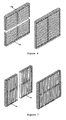
Figure 6 illustrates the combination of 2 standard panels [17a] [17b], arranged symmetrically according to a horizontal axis, in the vertical position, and as a resistant wall, with the boards [1] in the horizontal position. -
Figure 7 illustrates the combination of 2 standard panels [18a] [18b], arranged symmetrically according to a vertical axis, in the vertical position, and as a resistant wall, with the boards [1] in the vertical position. -
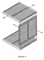
Figure 8 illustrates the standard combination/connection of the construction system, highlighting the slot between vertical panels (resistant wall) [17a] [17b] and horizontal panels (slab) [16a] [16b]. - This is a prefabricated system made up of a timber substructure which dictates the size of the panels. The standard panel, by way of example, has a total size of 3200 mm in length, 1600 mm wide and is 220 mm thick. Worthy of special mention as regards this size is the proportion of ½ between length and width which enables the possibility of different combinations. Notwithstanding, and as a way of complementing the range of applications of this system, there are other dimensions as is the case of panels measuring 2600 x 1600 mm, or 1600 x 1600 mm. Other panel thicknesses are also possible.
- The timber substructure - in the specific case, and for cost-effectiveness purposes, of resinous timber such as Scots pine, Pinus Sylvestris - is mainly made up - in the total proportion of eight out of eleven units - of 30 mm thick boards, with the sole exception being the last and the first two boards which incorporate different thicknesses. The solid timber boards (1), in a standard situation which is 220 mm wide and 3200 mm long (and with shafts going lengthwise in the part), are arranged in parallel and inter-spaced by way of solid timber blocks (2) at a constant height of 120 mm which constitutes said spacing. Between two boards, in other words, in the ten existing spacings, three blocks are always placed: two at the ends - with dimensions of 120 x 150 x 75 mm - and one exactly half way along the span - with dimensions of 120 x 150 x 150 mm. These timber blocks have the peculiarity of having their shafts oriented transversally to the boards that they are spacing. It should be pointed out that in terms of the vertical projection of these blocks vis-a-vis the 220 mm width of the boards, said blocks, occupying 150 mm, are 20 mm apart from one of the sides and must be 50 mm from the other. These 50 mm shall form the air lock which shall also be described later. All these elements are drilled beforehand (with boreholes whose diameter is of 14 mm) such that, when aligning each block, two M12 threaded steel bars (3) can be introduced. These bars, there being a total of six per panel, allow the final affixation and mechanical adjustment of the timber substructure using a dynamometric wrench which controls the tightening strength for washers and bolts which, introduced at low levels carried out on the exterior faces of the two boards placed at the end of the panel, ensure their alignment vis-a-vis the exterior plane of the timber parts.
- The three timber boards, whose thickness varies with regard to the usual 30 mm, are the first, second and last, respectively, measuring 115, 55 and 15 mm. Of the latter, the first two may suffer some variations in thickness - and this may cause the second to maintain the same 30 mm as the majority should the panel be serving as a slab - so as to adjust the adaptation of each panel to the context in which it is used. There is also the alternative of these first two boards - in the case of the panel to which they belong, serving as a vertical load-bearing element (structural wall) - having twenty 30 mm grooves throughout the width of the boards with a depth of 15 mm and inter-spaced 120 mm, so as to fit between them a total of twenty small timber boards (4) with dimensions of 125 x 220 x 30 mm, positioned transversally - just like the direction of their shafts - with regard to the two aforementioned boards. The main function of these smaller parts is the distribution of loads in an area in which the glass shall not have a structural function as shall be looked at below. Beforehand, it should also be pointed out that on the first board, which is 115 mm thick, there may be the need, in the event that the panel serves as a load-bearing wall, for there to be a series of grooves with a depth of 50 mm - 120 mm apart and with a width of 30 mm - on its exterior face, so as to receive the slotting of other panels situated perpendicularly to said panel, to wit when serving as a slab.
- On both sides - interior and exterior - of the timber substructure (5), and with the structural function of rigidifying it, a glass pane is placed (7). These glass panes are crucial for the functional and structural performance of the whole, hence the importance of the specific nature of their characteristics. However, they also play the important role of protecting the timber from atmospheric agents. Each pane of glass shall always have a size which coincides with the working length of the panel (15) on each of its faces - interior and exterior -, which in a standard situation corresponds to 3200 mm. The width of said panes of glass may vary between 1515 mm - in the case of a horizontal structural element (slab) - or 1375 mm - should it serve as a load-bearing vertical element (structural wall). This operation of the panel as a resistant vertical element ensures the possibility of operating in two different positions: in the first, suitable for Southward orientations, the positioning of the boards is horizontal (16a, 16b and 16c) (with the blocks serving as columns); in the second, particularly designed for Eastward and Westward orientations, the boards are arranged vertically (with the latter serving as columns) (17a and 17b). This is precisely the same panel but turned 90°, attesting to part of its multifunctionality which can only be attained based on its structural versatility. The two structural glass panes differ from each other by dint of the fact that they are in the interior or in the exterior. In the interior, single laminated glass is deployed - in the trials carried out, glass measuring 6 + 6 mm - with an edge was always tested. On the exterior, double-glazing shall be deployed comprising a single laminated glass pane (similar to the interior) on the interior face and a temperate glass pane (13) on the exterior face. This solution allows this exterior glass to work both as a structural element - by means of the laminated glass - and as a functional element during thermal and acoustic control and control of humidity which is harmful to timber - by means of the double-glazing solution. Simultaneously, the fact that temperate glass is being used on the exterior face allows a substantial increase in the resistance thereof to mechanical impact and also the assurance of safety as regards the thermal amplitude registered on the exterior face of the glass, something which is particularly relevant with glass of major dimensions. The exterior glass shall also foresee on the interior faces between the two panes, and on the precise projection of the adhesive bonding areas, a serigraphic black bar, with a view to protecting the adhesive connection of the ultraviolet radiation and preventing the viewing of any adhesive bonding imperfections. An important aspect is the possibility of the exterior laminated glass being photovoltaic, combining the structural function with the active energy function.
- The structural union process between the timber structure and the glass constitutes an important part of this system. In actual fact, only an adhesive which can effectively combine resistance and ductility can allow a combination of these materials. In this context, a semi-rigid, structural silicon, for instance, was used as an adhesive (8), after drying, being single-component, resistant to ultraviolet radiation and applicable at room temperature, of the Dow Corning brand - DC895 - which, by dint of its mechanical characteristics and, simultaneously the well-known resistance of silicon to atmospheric agents, ensures the desired effect. In other words, it ensures, to wit, the transmission of strains from the timber to the glass, and from the glass to the timber, enabling the glass to work as an effective reinforcement. And it will do so in uniform, ductile fashion, so as to allow the deformability of timber, preserving the integrity of the glass.
- The adhesive bonding of the glass to the timber is carried out in the vast majority of the area exposed on the side faces of the timber boards. However, worthy of special mention is the need to create a groove throughout the length of the timber boards with a width of 20 mm, centred on the board axis, and with a depth of 1.5 mm. Its purpose shall be to prevent the adhesive from spreading beyond said board, safeguarding the quality of the final finishing. To this end, it is necessary that in the two timber areas which remain in high relief, and with a width of 5 mm each, a spongy, acrylic bi-adhesive tape should be stuck to prevent said migration of the glue at the time of the pressing. The fact that the tape is bi-adhesive allows bonding to the timber and to the glass in effective fashion. The fact that it is spongy ensures that the air can be expelled and allows its crushing until the final adjustment at the height of the glue line.
- The adhesive bonding area thus corresponds to 20 mm x 3200 mm on both sides of each board. The exceptions to this rule are only the final board - which is only 15 mm and thus undergoes sticking throughout its width -, the second board - where the sticking is carried out throughout the length of the part, but along a constant width of 40 mm as it is a sensitive load distribution area - and on the first board which, as it is 115 mm thick, the glass is only stuck to it over 30 mm of its thickness face and only when the panel serves as a slab. This is because in situations where the panel serves as a structural wall, the glass is only stuck as from the second board, inclusive. This solution, in place between the first and second boards - and in the projection of the set of twenty small timber boards with dimensions of 125 x 220 x 30 mm referred to above -, allows sliding door and window frames to be introduced here on both sides of the panel whose purpose shall be the possibility of interior ventilation of the panel. These door and window frames, which may be made of aluminium, shall allow the inclusion of an interior (6) and exterior (14) window, and form an integral, essential part of the passive solar system which integrates this panel. This window opening and closing exercise shall be responsible for controlling the flow and movement in the natural circulation of air via the interior of the air lock to be found at the panel. These shall have a standard position defined on a seasonal basis: in the Summer, the natural position shall be that of closing the interior spans and opening the exterior ones, allowing the circulation of air so as to refresh the thermal mass which shall be inserted in the panel; in the Winter, the natural position of the spans shall be the opposite which will allow natural heating system inside the habitable space and, simultaneously, protection of the timber parts by way of the waterproofing provided by the exterior glass (12).
- In order for a natural circulation and convection system such as that mentioned above to work, there must be fenestrations for air circulation both at the top and at the base of the walls. Now, the asymmetry of the panels going to make up this invention, as well as the fact that there is only one fenestration on each side of the panel, only occurs because these panels are designed to be symmetrically overlaid according to the longitudinal axis which delimits the external face of the last board -15 mm thick -, allowing the total height of the construction surface to be 3200 mm and the apparent hinge to be a 30 mm board like all the others which adjoin it (when, in actual fact, they are two juxtaposed 15 mm boards). In this way, the face shall thus have fenestration at the top and another at its base, allowing the effective operation of the idealized bioclimatic system. In order for this system to be complete, there must be an effective air lock where said air can circulate fluidly, as well as the existence of an element with enough thermal mass to be assumed as a thermal accumulator. In the latter case, there shall be small gabions (11) - comprising, for example, stone from the region where the construction is eventually carried out, and with granolumetry which allows suitable luminic permeability -, prefabricated with a constant size of 120 x 120 x 1450 mm. These fit into the spacings between boards, resting on the interior side of the panel until they are only 20 mm apart from the interior laminated glass. This small space shall be completed by translucid thermal insulation (9) - as with the capillarity of the Okalux system and with thickness of 20 mm - which shall allow optimising the thermal performance of the product, as well as the protection of the interior glass by way of stone abrasion. As the gabions have a vertical projection of 120 mm, they must be 80 mm away from the interior face of the exterior glass: this interval shall constitute the aforementioned air lock - it should be noted that this 80 mm protuberance by the exterior face of the boards with regard to the exterior face of the gabions is vital so that in the Summer, contrarily to that which occurs in Winter when the Sun is lower in the sky, the timber parts exercise a necessary shading effect on the stones. In complementary fashion, and so that the air lock is fully operational, the timber boards must be, throughout their length and for a width equivalent to 80 mm on the exterior side, crossed by numerous small holes (10) which are 5 mm in diameter and 25 mm apart from each other, carried out in the workshop on a CNC machine. Said holes shall be proven not to constitute any reduction in the mechanical resistance of the whole, but rather make the necessary circulation of air feasible.
- On the exterior of the panel, and around 50 mm away from the latter, a metallic, stainless steel mesh shall be affixed onto a metallic guide attached to the upper board of the façade - of the Haver & Boecker type, for example - with standard dimensions of 2970 x 3200 mm. It shall serve the purpose of complementing the shading required by this system in the Summer. In terms of infrastructures, it should be stressed that the latter shall also be prefabricated and capable of incorporating systems for slotting and affixation between each other, insofar as they shall be inserted within the panels, to wit inside the spaces which are to be filled by the gabions. Under normal circumstances, the tubes shall pass inside the gabions adapted to receive them at the course to be found between the 2nd and 3rd boards.
- Finally, it is vital to return to the adhesive bonding system for the production process. Firstly, it is necessary to clean the surfaces of both substrata, to wit deploying cotton and acetone or ethyl alcohol. Once the surfaces are dry, the adhesive is applied at room temperature to the timber boards, being duly dosed and using a purpose-built gun. Concurrently, a second operator shall smooth and even out the surface of the adhesive using a spatula. This process shall run off quickly, in such a way that the adhesive does not start the setting process. Once this procedure has been completed, the interior glass is positioned - already duly cleaned on the face which is to be situated inside the panel - by a system of suckers, placing it on the timber substructure in its final position with regard to the latter. Finally, a press shall exert the force suitable for the union between the elements, in such a way that the thickness of the glue line is between 2 and 3 mm. The process shall subsequently be repeated for the other glass pane and the other side of the panel, but not without waiting for 72 hours. Self-evidently, when placing the gabions and the thermal insulation inside the panels, this will have to be carried out before bonding the second glass pane which shall always be the exterior glass. After bonding the second glass pane, the panel shall be put away for 2 weeks, fully supported on a horizontal surface until it can be handled. Only then can the sliding frames be assembled at the interior and exterior tops and bases, where applicable.
- Finally, this process shall give rise to a product that constitutes an "open system", transmitting high loads both on its plane and perpendicularly to it, being combinable with other structural systems and, by way of the substructure, adaptable to the specific aspects and each project, with the advantage of always using the same standard parts. Part of the key to this question will lie in the accessible possibility of connection/disconnection of the system component parts.
- In terms of safety, the resulting panel prevents the collapse of the system under all circumstances:
- Collapse of the timber substructure by traction: This is not possible owing to the action of the laminated glass and the adhesive, simultaneously;
- Buckling of the timber boards vis-a-vis the exterior: metallic bars do not allow it.
- Buckling of the timber boards vis-à-vis the interior: solid timber blocks do not allow it.
- The behaviour forecasts for this system were confirmed by way of the tests carried out at the Structures' Laboratory of the Civil Engineering Department of Minho University. When making a direct comparison between the behaviour of the timber substructure on its own and the mixed system, the following advantages were spotted as regards the second option:
- High mechanical resistance - increasing the maximum obtained by over 30%;
- The timber gave way first and the glass only later, attesting to the deformability of the glass on the plane in which it is being used and the suitability of its use;
- Ductile failure of the whole, avoiding fragile behaviour and first and foremost ensuring safety.
- Contribution of the glass to the effective strengthening of the structure. After its collapse, the load fell considerably and never rose again.
Claims (17)
- Timber-glass composite structural panel for construction which may be used as a slab or as a load-bearing wall, allowing the glass to exercise a structural reinforcement function characterised in that it is made up of:- a timber substructure [5] lengthwise consisting of parallel timber boards [1] spaced by timber blocks [2] ;- Two glass panes bonded [7] perpendicularly to the timber boards on both sides of the substructure by way of a structural adhesive [8].
- Structural panel according to the preceding claim characterised in that the timber boards and the blocks that constitute the timber substructure are fixed by way of steel bars [3] which cross the boards and blocks in the direction perpendicular to the boards.
- Structural panel according to claim 1 characterised in that the blocks which make the spacing between the parallel timber boards, so as to maintain a constant distance between them, are 3 between every 2 boards each one being placed at each end and one half way along the span.
- Structural panel according to claim 1, characterised in that the timber substructure has a 1:2 ratio between width and length.
- Structural panel according to claim 1, characterised in that the structural adhesive is placed on all exposed faces of the timber in order to rigidify the arrangement and allow the glass to serve as a reinforcement.
- Structural panel according to the preceding claim, characterised in that the structural adhesive is a single-component, resistant to ultraviolet radiation and in that it acquires a semi-rigid behaviour after drying.
- Structural panel according to the previous claim, characterised in that the structural adhesive allows a timber-glass connection rigidity between 5 and 20 kN/mm in compression cutting tests.
- Structural panel according to claim 1, characterised in that the glass on the interior side [7] of the substructure is a single laminate and the glass on the exterior side [12] of the substructure is a single or dual laminate, the glass being directly in contact with the laminated substructure [7] and the tempered exterior glass [13].
- Structural panel according to claim 1 characterised in that when it is used as a wall, it may include two sliding windows, one on the interior face [6] and the other on the exterior face [14], placed at the ends of the panel along its length, both at the same height, so as to allow the ventilation required for bioclimatic operation.
- Structural panel according to claim 9, characterised in that the spans of the substructure whereupon the sliding windows are placed including additional timber parts [4], parallel to each other, arranged perpendicularly to the boards so as to compensate the structural operation of the glass.
- Structural panel according to claims 9 and 10, characterised in that it is able to include between the parallel boards of the timber substructure stone gabions [11] with sufficient granulometry to allow the passage of light and a translucid thermal insulation layer [9] which, in conjunction with the windows, form a passive solar system so as to optimise the energy efficiency of the construction.
- Structural panel according to claim 11, characterised in that the timber boards have holes [10] for the circulation of air.
- Structural panel according to claims 9 to 12, characterised in that it is able to include an exterior sliding metallic mesh for shading complementary to the natural shading resulting from the parallel timber boards.
- Structural panel according to claims 9 to 13, characterised in that they are able to be placed either in a position in which the parallel timber boards are arranged horizontally, with the timber blocks serving as columns, or vertically, with the timber boards serving as columns.
- Panel production process according to claim 1, characterised in that it includes the following steps:a) assembly of timber substructure using the steel bars as guides for the timber boards and blocks which have been drilled beforehand;b) bonding of the interior glass using adhesive by way of a purpose-built gun throughout the exposed surface of the timber boards;c) pressing distributed evenly throughout the surface of the glass, manually or with appropriate industrial equipment, with the panel being in a horizontal position and totally supported on a hard, even surface;d) drying for an appropriate period, preferably of no less than 48 hours;e) bonding of the exterior glass, again using adhesive throughout the exposed surface of the timber boards.
- Panel production process according to the previous claim characterised in that it includes an additional step involving the placement of windows, one on the interior face and the other on the exterior face, placed at the ends of the panel throughout its length, both at the same height, by way of mechanical affixation of door and window frames in the timber substructure.
- Panel production process according to the previous claim characterised in that it includes an additional step involving the placement of gabions and translucid thermal insulation prior to the sticking of the exterior glass.
Applications Claiming Priority (2)
| Application Number | Priority Date | Filing Date | Title |
|---|---|---|---|
| PT104012A PT104012B (en) | 2008-04-03 | 2008-04-03 | MIXED WOOD-GLASS STRUCTURAL PANEL AND ITS PRODUCTION PROCESS |
| PCT/IB2009/005158 WO2009122269A1 (en) | 2008-04-03 | 2009-04-02 | Composite wood-glass structural panel and process for producing same |
Publications (2)
| Publication Number | Publication Date |
|---|---|
| EP2320002A1 true EP2320002A1 (en) | 2011-05-11 |
| EP2320002B1 EP2320002B1 (en) | 2011-10-26 |
Family
ID=40910002
Family Applications (1)
| Application Number | Title | Priority Date | Filing Date |
|---|---|---|---|
| EP09727148A Not-in-force EP2320002B1 (en) | 2008-04-03 | 2009-04-02 | Composite wood-glass structural panel and process for producing same |
Country Status (5)
| Country | Link |
|---|---|
| EP (1) | EP2320002B1 (en) |
| CN (1) | CN102046897A (en) |
| AT (1) | ATE530720T1 (en) |
| PT (1) | PT104012B (en) |
| WO (1) | WO2009122269A1 (en) |
Cited By (1)
| Publication number | Priority date | Publication date | Assignee | Title |
|---|---|---|---|---|
| WO2014033261A1 (en) * | 2012-09-03 | 2014-03-06 | Gerhard Seele | Structural element and method for producing a structural element |
Families Citing this family (4)
| Publication number | Priority date | Publication date | Assignee | Title |
|---|---|---|---|---|
| PT104073B (en) | 2008-05-21 | 2010-03-09 | Univ Do Minho | STRUCTURAL SYSTEM PORTICADO MISTO MADEIRA-VIDRO AND ITS PRODUCTION PROCESS |
| ES2538041B1 (en) * | 2013-12-16 | 2016-04-18 | Asoc. De Investigación Y Desarrollo En La Industria Del Mueble Y Afines (Aidima) | METHOD FOR THE MANUFACTURE OF LAMINATED GLASS WITH MODIFIED WOODEN SHEET AND ITS USE IN BUILDINGS |
| ES2538032B1 (en) * | 2013-12-16 | 2016-04-12 | Asoc. De Investigación Y Desarrollo En La Industria Del Mueble Y Afines (Aidima) | Method for the manufacture of laminated glass with natural wood veneer and its use in buildings |
| CN107395611A (en) | 2017-08-07 | 2017-11-24 | 成都牵牛草信息技术有限公司 | The method authorized in system to authorised operator |
Family Cites Families (14)
| Publication number | Priority date | Publication date | Assignee | Title |
|---|---|---|---|---|
| US2545906A (en) * | 1944-12-11 | 1951-03-20 | Libbey Owens Ford Glass Co | Multiple glass sheet glazing unit having enclosed angled metal slats |
| GB801790A (en) * | 1956-06-14 | 1958-09-24 | George Ingram | Improvements in heat-insulating panels |
| CH362202A (en) * | 1958-08-21 | 1962-05-31 | Waelli Ernst | Translucent, plate-shaped component |
| DE4207752A1 (en) | 1992-03-12 | 1993-09-16 | Holzbau Amann Gmbh | WOODEN PANEL |
| US5828494A (en) * | 1994-05-18 | 1998-10-27 | Stremple; Paul R. | Glass panel unit for refracting and dispersing light |
| DE19521027A1 (en) | 1994-06-23 | 1996-08-01 | Wellsteg Ag | Roof, wall, ceiling and=or floor chamber-element |
| DE19651444C2 (en) | 1996-12-11 | 2000-01-05 | Ver Glaswerke Gmbh | Component from a truss system |
| US6134842A (en) * | 1997-04-03 | 2000-10-24 | Cheng; Chi | Integrated window/light shelf system |
| US6546690B1 (en) | 1998-02-24 | 2003-04-15 | Glasfabrik Lamberts Gmbh & Co. Kg | Glass structural element for constructing a preferably self supporting wall, roof or ceiling section or element |
| FR2775710A1 (en) * | 1998-03-05 | 1999-09-10 | Everlite Concept Sa | POLYCARBONATE CASSETTE FOR COVERING OR WALL |
| ITBS20010068A1 (en) | 2001-09-12 | 2003-03-12 | Michel Palumbo | TRANSPARENT STRUCTURAL ELEMENT WITH INCREASED SECURITY |
| AT5985U1 (en) | 2001-11-20 | 2003-02-25 | Klh Massivholz Gesmbh | FERTIGTEILWERK COMPONENT |
| BE1016607A3 (en) | 2005-05-31 | 2007-02-06 | Glaverbel | Structural element of construction glass. |
| DE102006044649B3 (en) | 2006-09-21 | 2007-11-29 | Seele Gmbh & Co. Kg | Self-supporting architectural glass structure e.g. to support a building facade has transverse bolts through void |
-
2008
- 2008-04-03 PT PT104012A patent/PT104012B/en not_active IP Right Cessation
-
2009
- 2009-04-02 WO PCT/IB2009/005158 patent/WO2009122269A1/en not_active Ceased
- 2009-04-02 EP EP09727148A patent/EP2320002B1/en not_active Not-in-force
- 2009-04-02 AT AT09727148T patent/ATE530720T1/en not_active IP Right Cessation
- 2009-04-02 CN CN2009801196365A patent/CN102046897A/en active Pending
Non-Patent Citations (1)
| Title |
|---|
| See references of WO2009122269A1 * |
Cited By (1)
| Publication number | Priority date | Publication date | Assignee | Title |
|---|---|---|---|---|
| WO2014033261A1 (en) * | 2012-09-03 | 2014-03-06 | Gerhard Seele | Structural element and method for producing a structural element |
Also Published As
| Publication number | Publication date |
|---|---|
| PT104012B (en) | 2010-03-31 |
| CN102046897A (en) | 2011-05-04 |
| ATE530720T1 (en) | 2011-11-15 |
| PT104012A (en) | 2009-10-06 |
| EP2320002B1 (en) | 2011-10-26 |
| WO2009122269A1 (en) | 2009-10-08 |
Similar Documents
| Publication | Publication Date | Title |
|---|---|---|
| EP0799949B1 (en) | Natural stone element | |
| EP2320002B1 (en) | Composite wood-glass structural panel and process for producing same | |
| EP2350404B1 (en) | Wall design made of plates | |
| CZ219894A3 (en) | Safety glass element with heat-insulating properties and process for producing thereof | |
| CN205475694U (en) | Assembled steel construction house | |
| DE102019128118A1 (en) | Facade element and process for the energetic renovation of buildings | |
| DE202019000008U1 (en) | Wall construction of panels with high carbon content | |
| DE202011102156U1 (en) | Insulation module for walls with integrated moisture and energy management | |
| Stepinac et al. | Timber-structural glass composite systems in earthquake environment | |
| EP4368792B1 (en) | Method for energy-based construction renovation | |
| EP2350536A1 (en) | Component and use of a component | |
| DE102008051332A1 (en) | Device for manufacturing assembly system for flat roof-solar plants, particularly for assembly on flat roofs, has block comprising hard weather-resistant polyurethane foam, where bottom surface of block corresponds to size of solar system | |
| Cruz et al. | Structural timber-glass adhesive bonding | |
| Winter et al. | Load bearing and stiffening timber-glass-composites (TGC) | |
| DE202023000351U1 (en) | Thermally insulated lightweight wall as building cladding for the serial renovation of existing buildings | |
| Fadai et al. | Application of timber-glass composite (TGC) structures for building construction | |
| Bos et al. | Structural glass in architecture | |
| EP1365082B1 (en) | Panel | |
| DE19847110C2 (en) | Component for creating load-bearing walls, ceilings, floors or roofs | |
| Pequeno et al. | Structural timber-glass linear system: characterization & architectural potentialities | |
| CN222025372U (en) | High-performance anti-drop ultrathin porcelain plate facing heat-insulation and decoration integrated plate | |
| EP1155198A1 (en) | Wall construction | |
| PT104073A (en) | STRUCTURAL SYSTEM PORTICADO MISTO MADEIRA-VIDRO AND ITS PRODUCTION PROCESS | |
| DE202022000925U1 (en) | Lightweight facade panel | |
| EP2826928B1 (en) | Building facade or roof with natural stone panels or ceramic tiles and method for manufacture |
Legal Events
| Date | Code | Title | Description |
|---|---|---|---|
| PUAI | Public reference made under article 153(3) epc to a published international application that has entered the european phase |
Free format text: ORIGINAL CODE: 0009012 |
|
| PUAI | Public reference made under article 153(3) epc to a published international application that has entered the european phase |
Free format text: ORIGINAL CODE: 0009012 |
|
| GRAP | Despatch of communication of intention to grant a patent |
Free format text: ORIGINAL CODE: EPIDOSNIGR1 |
|
| 17P | Request for examination filed |
Effective date: 20101102 |
|
| AK | Designated contracting states |
Kind code of ref document: A1 Designated state(s): AT BE BG CH CY CZ DE DK EE ES FI FR GB GR HR HU IE IS IT LI LT LU LV MC MK MT NL NO PL PT RO SE SI SK TR |
|
| AX | Request for extension of the european patent |
Extension state: AL BA RS |
|
| DAX | Request for extension of the european patent (deleted) | ||
| GRAS | Grant fee paid |
Free format text: ORIGINAL CODE: EPIDOSNIGR3 |
|
| GRAA | (expected) grant |
Free format text: ORIGINAL CODE: 0009210 |
|
| AK | Designated contracting states |
Kind code of ref document: B1 Designated state(s): AT BE BG CH CY CZ DE DK EE ES FI FR GB GR HR HU IE IS IT LI LT LU LV MC MK MT NL NO PL PT RO SE SI SK TR |
|
| REG | Reference to a national code |
Ref country code: GB Ref legal event code: FG4D |
|
| REG | Reference to a national code |
Ref country code: CH Ref legal event code: EP |
|
| REG | Reference to a national code |
Ref country code: IE Ref legal event code: FG4D |
|
| REG | Reference to a national code |
Ref country code: DE Ref legal event code: R096 Ref document number: 602009003343 Country of ref document: DE Effective date: 20111222 |
|
| REG | Reference to a national code |
Ref country code: NL Ref legal event code: VDEP Effective date: 20111026 |
|
| LTIE | Lt: invalidation of european patent or patent extension |
Effective date: 20111026 |
|
| REG | Reference to a national code |
Ref country code: AT Ref legal event code: MK05 Ref document number: 530720 Country of ref document: AT Kind code of ref document: T Effective date: 20111026 |
|
| PG25 | Lapsed in a contracting state [announced via postgrant information from national office to epo] |
Ref country code: LT Free format text: LAPSE BECAUSE OF FAILURE TO SUBMIT A TRANSLATION OF THE DESCRIPTION OR TO PAY THE FEE WITHIN THE PRESCRIBED TIME-LIMIT Effective date: 20111026 Ref country code: NO Free format text: LAPSE BECAUSE OF FAILURE TO SUBMIT A TRANSLATION OF THE DESCRIPTION OR TO PAY THE FEE WITHIN THE PRESCRIBED TIME-LIMIT Effective date: 20120126 Ref country code: BE Free format text: LAPSE BECAUSE OF FAILURE TO SUBMIT A TRANSLATION OF THE DESCRIPTION OR TO PAY THE FEE WITHIN THE PRESCRIBED TIME-LIMIT Effective date: 20111026 Ref country code: IS Free format text: LAPSE BECAUSE OF FAILURE TO SUBMIT A TRANSLATION OF THE DESCRIPTION OR TO PAY THE FEE WITHIN THE PRESCRIBED TIME-LIMIT Effective date: 20120226 |
|
| PGFP | Annual fee paid to national office [announced via postgrant information from national office to epo] |
Ref country code: FR Payment date: 20120214 Year of fee payment: 4 |
|
| PG25 | Lapsed in a contracting state [announced via postgrant information from national office to epo] |
Ref country code: NL Free format text: LAPSE BECAUSE OF FAILURE TO SUBMIT A TRANSLATION OF THE DESCRIPTION OR TO PAY THE FEE WITHIN THE PRESCRIBED TIME-LIMIT Effective date: 20111026 Ref country code: PT Free format text: LAPSE BECAUSE OF FAILURE TO SUBMIT A TRANSLATION OF THE DESCRIPTION OR TO PAY THE FEE WITHIN THE PRESCRIBED TIME-LIMIT Effective date: 20120227 Ref country code: HR Free format text: LAPSE BECAUSE OF FAILURE TO SUBMIT A TRANSLATION OF THE DESCRIPTION OR TO PAY THE FEE WITHIN THE PRESCRIBED TIME-LIMIT Effective date: 20111026 Ref country code: SE Free format text: LAPSE BECAUSE OF FAILURE TO SUBMIT A TRANSLATION OF THE DESCRIPTION OR TO PAY THE FEE WITHIN THE PRESCRIBED TIME-LIMIT Effective date: 20111026 Ref country code: PL Free format text: LAPSE BECAUSE OF FAILURE TO SUBMIT A TRANSLATION OF THE DESCRIPTION OR TO PAY THE FEE WITHIN THE PRESCRIBED TIME-LIMIT Effective date: 20111026 Ref country code: SI Free format text: LAPSE BECAUSE OF FAILURE TO SUBMIT A TRANSLATION OF THE DESCRIPTION OR TO PAY THE FEE WITHIN THE PRESCRIBED TIME-LIMIT Effective date: 20111026 Ref country code: LV Free format text: LAPSE BECAUSE OF FAILURE TO SUBMIT A TRANSLATION OF THE DESCRIPTION OR TO PAY THE FEE WITHIN THE PRESCRIBED TIME-LIMIT Effective date: 20111026 |
|
| PG25 | Lapsed in a contracting state [announced via postgrant information from national office to epo] |
Ref country code: CY Free format text: LAPSE BECAUSE OF FAILURE TO SUBMIT A TRANSLATION OF THE DESCRIPTION OR TO PAY THE FEE WITHIN THE PRESCRIBED TIME-LIMIT Effective date: 20111026 |
|
| PG25 | Lapsed in a contracting state [announced via postgrant information from national office to epo] |
Ref country code: SK Free format text: LAPSE BECAUSE OF FAILURE TO SUBMIT A TRANSLATION OF THE DESCRIPTION OR TO PAY THE FEE WITHIN THE PRESCRIBED TIME-LIMIT Effective date: 20111026 Ref country code: DK Free format text: LAPSE BECAUSE OF FAILURE TO SUBMIT A TRANSLATION OF THE DESCRIPTION OR TO PAY THE FEE WITHIN THE PRESCRIBED TIME-LIMIT Effective date: 20111026 Ref country code: BG Free format text: LAPSE BECAUSE OF FAILURE TO SUBMIT A TRANSLATION OF THE DESCRIPTION OR TO PAY THE FEE WITHIN THE PRESCRIBED TIME-LIMIT Effective date: 20120126 Ref country code: EE Free format text: LAPSE BECAUSE OF FAILURE TO SUBMIT A TRANSLATION OF THE DESCRIPTION OR TO PAY THE FEE WITHIN THE PRESCRIBED TIME-LIMIT Effective date: 20111026 Ref country code: CZ Free format text: LAPSE BECAUSE OF FAILURE TO SUBMIT A TRANSLATION OF THE DESCRIPTION OR TO PAY THE FEE WITHIN THE PRESCRIBED TIME-LIMIT Effective date: 20111026 |
|
| PG25 | Lapsed in a contracting state [announced via postgrant information from national office to epo] |
Ref country code: RO Free format text: LAPSE BECAUSE OF FAILURE TO SUBMIT A TRANSLATION OF THE DESCRIPTION OR TO PAY THE FEE WITHIN THE PRESCRIBED TIME-LIMIT Effective date: 20111026 Ref country code: IT Free format text: LAPSE BECAUSE OF FAILURE TO SUBMIT A TRANSLATION OF THE DESCRIPTION OR TO PAY THE FEE WITHIN THE PRESCRIBED TIME-LIMIT Effective date: 20111026 |
|
| PLBE | No opposition filed within time limit |
Free format text: ORIGINAL CODE: 0009261 |
|
| STAA | Information on the status of an ep patent application or granted ep patent |
Free format text: STATUS: NO OPPOSITION FILED WITHIN TIME LIMIT |
|
| 26N | No opposition filed |
Effective date: 20120727 |
|
| REG | Reference to a national code |
Ref country code: DE Ref legal event code: R097 Ref document number: 602009003343 Country of ref document: DE Effective date: 20120727 |
|
| PG25 | Lapsed in a contracting state [announced via postgrant information from national office to epo] |
Ref country code: MC Free format text: LAPSE BECAUSE OF NON-PAYMENT OF DUE FEES Effective date: 20120430 |
|
| PGFP | Annual fee paid to national office [announced via postgrant information from national office to epo] |
Ref country code: DE Payment date: 20120910 Year of fee payment: 4 |
|
| REG | Reference to a national code |
Ref country code: IE Ref legal event code: MM4A |
|
| PG25 | Lapsed in a contracting state [announced via postgrant information from national office to epo] |
Ref country code: IE Free format text: LAPSE BECAUSE OF NON-PAYMENT OF DUE FEES Effective date: 20120402 Ref country code: AT Free format text: LAPSE BECAUSE OF FAILURE TO SUBMIT A TRANSLATION OF THE DESCRIPTION OR TO PAY THE FEE WITHIN THE PRESCRIBED TIME-LIMIT Effective date: 20111026 |
|
| PG25 | Lapsed in a contracting state [announced via postgrant information from national office to epo] |
Ref country code: MK Free format text: LAPSE BECAUSE OF FAILURE TO SUBMIT A TRANSLATION OF THE DESCRIPTION OR TO PAY THE FEE WITHIN THE PRESCRIBED TIME-LIMIT Effective date: 20111026 |
|
| PG25 | Lapsed in a contracting state [announced via postgrant information from national office to epo] |
Ref country code: ES Free format text: LAPSE BECAUSE OF FAILURE TO SUBMIT A TRANSLATION OF THE DESCRIPTION OR TO PAY THE FEE WITHIN THE PRESCRIBED TIME-LIMIT Effective date: 20120206 |
|
| PG25 | Lapsed in a contracting state [announced via postgrant information from national office to epo] |
Ref country code: FI Free format text: LAPSE BECAUSE OF FAILURE TO SUBMIT A TRANSLATION OF THE DESCRIPTION OR TO PAY THE FEE WITHIN THE PRESCRIBED TIME-LIMIT Effective date: 20111026 |
|
| PG25 | Lapsed in a contracting state [announced via postgrant information from national office to epo] |
Ref country code: MT Free format text: LAPSE BECAUSE OF FAILURE TO SUBMIT A TRANSLATION OF THE DESCRIPTION OR TO PAY THE FEE WITHIN THE PRESCRIBED TIME-LIMIT Effective date: 20111026 |
|
| REG | Reference to a national code |
Ref country code: CH Ref legal event code: PL |
|
| GBPC | Gb: european patent ceased through non-payment of renewal fee |
Effective date: 20130402 |
|
| PG25 | Lapsed in a contracting state [announced via postgrant information from national office to epo] |
Ref country code: CH Free format text: LAPSE BECAUSE OF NON-PAYMENT OF DUE FEES Effective date: 20130430 Ref country code: GB Free format text: LAPSE BECAUSE OF NON-PAYMENT OF DUE FEES Effective date: 20130402 Ref country code: DE Free format text: LAPSE BECAUSE OF NON-PAYMENT OF DUE FEES Effective date: 20131101 Ref country code: LI Free format text: LAPSE BECAUSE OF NON-PAYMENT OF DUE FEES Effective date: 20130430 |
|
| REG | Reference to a national code |
Ref country code: FR Ref legal event code: ST Effective date: 20131231 |
|
| REG | Reference to a national code |
Ref country code: DE Ref legal event code: R119 Ref document number: 602009003343 Country of ref document: DE Effective date: 20131101 |
|
| PG25 | Lapsed in a contracting state [announced via postgrant information from national office to epo] |
Ref country code: FR Free format text: LAPSE BECAUSE OF NON-PAYMENT OF DUE FEES Effective date: 20130430 |
|
| PG25 | Lapsed in a contracting state [announced via postgrant information from national office to epo] |
Ref country code: TR Free format text: LAPSE BECAUSE OF FAILURE TO SUBMIT A TRANSLATION OF THE DESCRIPTION OR TO PAY THE FEE WITHIN THE PRESCRIBED TIME-LIMIT Effective date: 20111026 |
|
| PG25 | Lapsed in a contracting state [announced via postgrant information from national office to epo] |
Ref country code: LU Free format text: LAPSE BECAUSE OF NON-PAYMENT OF DUE FEES Effective date: 20120402 |
|
| PG25 | Lapsed in a contracting state [announced via postgrant information from national office to epo] |
Ref country code: HU Free format text: LAPSE BECAUSE OF FAILURE TO SUBMIT A TRANSLATION OF THE DESCRIPTION OR TO PAY THE FEE WITHIN THE PRESCRIBED TIME-LIMIT Effective date: 20090402 |
|
| PG25 | Lapsed in a contracting state [announced via postgrant information from national office to epo] |
Ref country code: GR Free format text: LAPSE BECAUSE OF FAILURE TO SUBMIT A TRANSLATION OF THE DESCRIPTION OR TO PAY THE FEE WITHIN THE PRESCRIBED TIME-LIMIT Effective date: 20111026 |