EP2320076A2 - Système de pale d'éolienne pour fournir un flux contrôlé de fluide provenant de ou envoyé vers une surface de la pale - Google Patents
Système de pale d'éolienne pour fournir un flux contrôlé de fluide provenant de ou envoyé vers une surface de la pale Download PDFInfo
- Publication number
- EP2320076A2 EP2320076A2 EP10189247A EP10189247A EP2320076A2 EP 2320076 A2 EP2320076 A2 EP 2320076A2 EP 10189247 A EP10189247 A EP 10189247A EP 10189247 A EP10189247 A EP 10189247A EP 2320076 A2 EP2320076 A2 EP 2320076A2
- Authority
- EP
- European Patent Office
- Prior art keywords
- fluid
- wind turbine
- blade
- openings
- opening
- Prior art date
- Legal status (The legal status is an assumption and is not a legal conclusion. Google has not performed a legal analysis and makes no representation as to the accuracy of the status listed.)
- Withdrawn
Links
- 239000012530 fluid Substances 0.000 title claims abstract description 190
- 238000000034 method Methods 0.000 description 15
- 230000008901 benefit Effects 0.000 description 14
- 239000000463 material Substances 0.000 description 4
- 230000004044 response Effects 0.000 description 4
- 238000007664 blowing Methods 0.000 description 3
- 230000008859 change Effects 0.000 description 3
- 238000001816 cooling Methods 0.000 description 3
- 230000008878 coupling Effects 0.000 description 3
- 238000010168 coupling process Methods 0.000 description 3
- 238000005859 coupling reaction Methods 0.000 description 3
- 230000000694 effects Effects 0.000 description 3
- 230000009286 beneficial effect Effects 0.000 description 2
- 238000004519 manufacturing process Methods 0.000 description 2
- 238000005086 pumping Methods 0.000 description 2
- 238000011144 upstream manufacturing Methods 0.000 description 2
- XLYOFNOQVPJJNP-UHFFFAOYSA-N water Substances O XLYOFNOQVPJJNP-UHFFFAOYSA-N 0.000 description 2
- 230000003190 augmentative effect Effects 0.000 description 1
- 230000000903 blocking effect Effects 0.000 description 1
- 239000006227 byproduct Substances 0.000 description 1
- 239000002131 composite material Substances 0.000 description 1
- 230000001419 dependent effect Effects 0.000 description 1
- 238000010586 diagram Methods 0.000 description 1
- 229920001971 elastomer Polymers 0.000 description 1
- 238000005516 engineering process Methods 0.000 description 1
- 239000004744 fabric Substances 0.000 description 1
- 239000011152 fibreglass Substances 0.000 description 1
- 239000002803 fossil fuel Substances 0.000 description 1
- 238000009434 installation Methods 0.000 description 1
- 239000007788 liquid Substances 0.000 description 1
- 238000012986 modification Methods 0.000 description 1
- 230000004048 modification Effects 0.000 description 1
- 230000001473 noxious effect Effects 0.000 description 1
- 230000001151 other effect Effects 0.000 description 1
- 239000004033 plastic Substances 0.000 description 1
- 229920003023 plastic Polymers 0.000 description 1
- 229920002635 polyurethane Polymers 0.000 description 1
- 239000004814 polyurethane Substances 0.000 description 1
- 239000007787 solid Substances 0.000 description 1
Images


Classifications
-
- F—MECHANICAL ENGINEERING; LIGHTING; HEATING; WEAPONS; BLASTING
- F03—MACHINES OR ENGINES FOR LIQUIDS; WIND, SPRING, OR WEIGHT MOTORS; PRODUCING MECHANICAL POWER OR A REACTIVE PROPULSIVE THRUST, NOT OTHERWISE PROVIDED FOR
- F03D—WIND MOTORS
- F03D1/00—Wind motors with rotation axis substantially parallel to the air flow entering the rotor
- F03D1/06—Rotors
- F03D1/065—Rotors characterised by their construction elements
- F03D1/0675—Rotors characterised by their construction elements of the blades
-
- F—MECHANICAL ENGINEERING; LIGHTING; HEATING; WEAPONS; BLASTING
- F03—MACHINES OR ENGINES FOR LIQUIDS; WIND, SPRING, OR WEIGHT MOTORS; PRODUCING MECHANICAL POWER OR A REACTIVE PROPULSIVE THRUST, NOT OTHERWISE PROVIDED FOR
- F03D—WIND MOTORS
- F03D15/00—Transmission of mechanical power
- F03D15/05—Transmission of mechanical power using hollow exhausting blades
-
- F—MECHANICAL ENGINEERING; LIGHTING; HEATING; WEAPONS; BLASTING
- F03—MACHINES OR ENGINES FOR LIQUIDS; WIND, SPRING, OR WEIGHT MOTORS; PRODUCING MECHANICAL POWER OR A REACTIVE PROPULSIVE THRUST, NOT OTHERWISE PROVIDED FOR
- F03D—WIND MOTORS
- F03D7/00—Controlling wind motors
- F03D7/02—Controlling wind motors the wind motors having rotation axis substantially parallel to the air flow entering the rotor
- F03D7/022—Adjusting aerodynamic properties of the blades
-
- F—MECHANICAL ENGINEERING; LIGHTING; HEATING; WEAPONS; BLASTING
- F05—INDEXING SCHEMES RELATING TO ENGINES OR PUMPS IN VARIOUS SUBCLASSES OF CLASSES F01-F04
- F05B—INDEXING SCHEME RELATING TO WIND, SPRING, WEIGHT, INERTIA OR LIKE MOTORS, TO MACHINES OR ENGINES FOR LIQUIDS COVERED BY SUBCLASSES F03B, F03D AND F03G
- F05B2240/00—Components
- F05B2240/10—Stators
- F05B2240/12—Fluid guiding means, e.g. vanes
- F05B2240/122—Vortex generators, turbulators, or the like, for mixing
-
- F—MECHANICAL ENGINEERING; LIGHTING; HEATING; WEAPONS; BLASTING
- F05—INDEXING SCHEMES RELATING TO ENGINES OR PUMPS IN VARIOUS SUBCLASSES OF CLASSES F01-F04
- F05B—INDEXING SCHEME RELATING TO WIND, SPRING, WEIGHT, INERTIA OR LIKE MOTORS, TO MACHINES OR ENGINES FOR LIQUIDS COVERED BY SUBCLASSES F03B, F03D AND F03G
- F05B2240/00—Components
- F05B2240/20—Rotors
- F05B2240/30—Characteristics of rotor blades, i.e. of any element transforming dynamic fluid energy to or from rotational energy and being attached to a rotor
- F05B2240/301—Cross-section characteristics
-
- F—MECHANICAL ENGINEERING; LIGHTING; HEATING; WEAPONS; BLASTING
- F05—INDEXING SCHEMES RELATING TO ENGINES OR PUMPS IN VARIOUS SUBCLASSES OF CLASSES F01-F04
- F05B—INDEXING SCHEME RELATING TO WIND, SPRING, WEIGHT, INERTIA OR LIKE MOTORS, TO MACHINES OR ENGINES FOR LIQUIDS COVERED BY SUBCLASSES F03B, F03D AND F03G
- F05B2240/00—Components
- F05B2240/20—Rotors
- F05B2240/30—Characteristics of rotor blades, i.e. of any element transforming dynamic fluid energy to or from rotational energy and being attached to a rotor
- F05B2240/305—Flaps, slats or spoilers
- F05B2240/3052—Flaps, slats or spoilers adjustable
-
- F—MECHANICAL ENGINEERING; LIGHTING; HEATING; WEAPONS; BLASTING
- F05—INDEXING SCHEMES RELATING TO ENGINES OR PUMPS IN VARIOUS SUBCLASSES OF CLASSES F01-F04
- F05B—INDEXING SCHEME RELATING TO WIND, SPRING, WEIGHT, INERTIA OR LIKE MOTORS, TO MACHINES OR ENGINES FOR LIQUIDS COVERED BY SUBCLASSES F03B, F03D AND F03G
- F05B2260/00—Function
- F05B2260/60—Fluid transfer
-
- Y—GENERAL TAGGING OF NEW TECHNOLOGICAL DEVELOPMENTS; GENERAL TAGGING OF CROSS-SECTIONAL TECHNOLOGIES SPANNING OVER SEVERAL SECTIONS OF THE IPC; TECHNICAL SUBJECTS COVERED BY FORMER USPC CROSS-REFERENCE ART COLLECTIONS [XRACs] AND DIGESTS
- Y02—TECHNOLOGIES OR APPLICATIONS FOR MITIGATION OR ADAPTATION AGAINST CLIMATE CHANGE
- Y02E—REDUCTION OF GREENHOUSE GAS [GHG] EMISSIONS, RELATED TO ENERGY GENERATION, TRANSMISSION OR DISTRIBUTION
- Y02E10/00—Energy generation through renewable energy sources
- Y02E10/70—Wind energy
- Y02E10/72—Wind turbines with rotation axis in wind direction
Definitions
- the present disclosure is generally directed to wind turbines and, in particular, systems and methods for altering the aerodynamics of wind turbine blades.
- Wind power and the use of wind turbines have gained increased attention as the quest for alternative energy sources continues.
- Wind power may be considered one of the cleanest, most environmentally friendly energy sources presently available.
- Different from traditional fossil fuel sources wind power is completely renewable and does not produce noxious or environmentally harmful by-products.
- technological advances in the art have allowed for increased sizes of wind turbines and new designs of wind turbine components. As the physical sizes and availability of wind turbines increase, so does the need to balance the cost of manufacturing and operating wind turbines to further allow wind power to be cost-competitive with other energy sources.
- a modem wind turbine typically includes a tower, a generator, a gearbox, a nacelle, and one or more blades.
- the blades capture the kinetic energy of wind using aerodynamic principles known in the art.
- the blades transmit the kinetic energy in the form of rotational energy so as to turn a shaft coupling the blades to a gearbox, or if a gearbox is not used, directly to the generator.
- the generator then converts the mechanical energy to electrical energy that may be deployed to a utility grid.
- the size, shape, and weight of the blades are factors that contribute to energy efficiencies of wind turbines. For example, an increase in blade size increases the energy production of a wind turbine, while a decrease in weight also furthers the value of a wind turbine.
- large commercial wind turbines are capable of generating between one and one-half megawatts to five megawatts of power. Efforts to increase blade size and improve blade aerodynamics assist in the continued growth of wind turbine technology and the adoption of wind energy as an alternative energy source. Current wind turbine blades have limited ability to alter their aerodynamics.
- One aspect of the present disclosure includes a wind turbine blade system having a controller and a blade rotatably attached to a rotor of a wind turbine.
- the system further includes one or more openings disposed along at least one surface of the blade and a fluid moving device arranged and disposed to provide a fluid to or from the one or more openings.
- a controlled amount of fluid is provided to the one or more openings, and the controlled amount is determined by the controller.
- Another aspect of the present disclosure includes a controller and a plurality of blades rotatably attached to a rotor of the wind turbine. At least one of the plurality of blades includes one or more openings.
- a fluid moving device is arranged and disposed to provide a fluid to or from the one or more openings.
- a controlled amount of fluid is provided to the one or more openings, and the controlled amount is determined by the controller.
- Still another aspect of the present disclosure includes a method for operating a wind turbine.
- the method includes providing a blade having one or more openings.
- the method further includes sensing an operating condition.
- An amount of fluid flow desired is determined in response to the operating condition sensed.
- the amount of fluid is provided to or from the openings.
- An advantage of the present disclosure includes the ability to controllably alter the aerodynamics of wind turbine blades.
- Another advantage of the present disclosure includes the ability to flow fluid, such as air, over components of the wind turbine for cooling, such as within the nacelle.
- Still another advantage of the present disclosure is the ability to control fluid flow over individual blades in a controlled fashion to balance or otherwise control the aerodynamics or loads of individual blades.
- Still another advantage of the present disclosure is the ability to couple metering methods with a control system that includes feedback to better control the aerodynamics of the blade.
- the wind turbine 100 includes a nacelle 102 mounted atop a tall tower 104, only a portion of which is shown in FIG. 1 .
- the nacelle 102 houses turbine components, such as a generator (not shown), gearbox (not shown), control equipment (not shown) and other turbine components.
- Wind turbine 100 also comprises a wind turbine rotor 106 that includes one or more blades 108 attached to a rotating hub 110.
- wind turbine 100 illustrated in FIG. 1 includes three blades 108, there are no specific limits on the number of blades 108 that can be used.
- Blades 108 may include hollow reinforced composite structures fabricated from any suitable material known for forming blades 108. As shown in FIG.
- each blade 108 has an airfoil portion 111 extending from the tip 113 ( FIG. 1 ) to the root 115 or root portion, which is connectable to the hub 110 of the wind turbine.
- the height of tower 104 is selected based upon factors and conditions known in the art.
- rotor 106 may have blades 108 of any shape, and may have blades 108 of any type and/or any configuration, whether or not such shape, type, and/or configuration is described and/or illustrated herein.
- One example of another type, shape, and/or configuration of blades 108 is a ducted rotor (not shown) having a turbine (not shown) contained within a duct (not shown).
- Another example of another type, shape, and/or configuration of blades 108 is a darrieus wind turbine, sometimes referred to as an "eggbeater" turbine.
- Yet another example of another type, shape, and/or configuration of blades 108 is a savonious wind turbine.
- wind turbine 100 may, in some embodiments, be a wind turbine wherein rotor 106 generally faces upwind to harness wind energy, and/or may be a wind turbine wherein rotor 106 generally faces downwind to harness energy.
- rotor 106 may not face exactly upwind and/or downwind, but may face generally at any angle (which may be variable) with respect to a direction of the wind to harness energy therefrom.
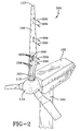
- the present disclosure includes a wind turbine blade system 200 having a plurality of openings 203 disposed within an opening module 205 on a blade 108.
- the openings 203 are configured to permit fluid passage from the interior of blade 108 to the exterior of blade 108. Openings 203 may also be configured to ingest external flow and pass it into the interior of blade 108. While the openings 203 are shown as being present as portions of opening modules 205, the disclosure is not so limited. In other embodiments, the openings 203 may be formed directly into blade 108 or may be individually or grouped together.
- the opening module 205 provides controllable flow of fluid from the interior of blade 108 to the exterior of blade 108.
- the opening 203 provides controllable flow from the exterior of blade 108 to the interior of blade 108.
- the openings 203 and opening module 205 may include any suitable geometry or structure that permits the controlled flow of fluid.
- the modules 205 include openings 203 having geometry providing orientation or direction such that the fluid flowing through openings 203 are directed in a predetermined direction.
- Suitable structures for directing the flow may include ducts, nozzles, variable blockage devices, guiding valves, louvers or other fluid directing structures that may be fixed or adjustable to provide fluid flow in a predetermined direction.
- the openings 203 may permit unregulated or unrestricted flow of fluid.
- the blade system 200 of the present disclosure further includes a fluid moving device 207, such as, but not limited to a blower, fan, compressor, pump or other device capable of moving or accelerating fluid.
- the fluid moving device 207 directs a fluid flow 209 into the interior portion of blade 108.
- the fluid provided to openings 203 is air. Air may be drawn into the turbine at any suitable location.
- vents may be provided in the nacelle 102 to permit the drawing in of air into the system 200.
- vents in the blade 108 or the hub 110 may be utilized to draw in air.
- Another embodiment may include drawing air into the system 200 via one set of openings 203 and providing the air to a second set of openings 203. While air is being described as a suitable fluid, other fluids, such as gasses, including compressed or heated gasses, or fluids, such as water or other liquids may be provided to openings 203.
- the opening module 205 includes a fluid restricting device 301 (see FIG. 3 ).
- the fluid restricting device 301 may include a plate or solid component that selectively blocks one or more openings 203 of opening module 205 to restrict flow of fluid.
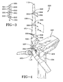
- the present disclosure includes another embodiment of a wind turbine blade system 200 having a plurality of openings 203 disposed on an opening module 205.
- the system 200 includes the arrangement of blade 108, opening module 205 with openings 203 and hub 110 shown and disclosed in FIG. 1 above.
- the system 200 includes an exhaust duct 401 and a suction duct 403.
- the exhaust duct 401 includes a conduit or other fluid conveying space extending from the fluid moving device 207 to the openings 203 and receives a fluid flow 209 from the fluid moving device.
- the suction duct 403 includes a conduit or other fluid conveying space extending from an inlet area (not shown) to the fluid moving device 207.
- the inlet area may be an interior or exterior vent, a location within the nacelle 102, a location within the tower 104 or fluid source, such as a fluid containing vessel.
- the arrangement of the exhaust duct 401 and suction duct 403 is not limited to the arrangement shown.
- the number of exhaust ducts 401 and suction ducts 403 is not limited.
- individual exhaust ducts 401 may be utilized for each opening 203.
- dampers, manifolds or other devices may be used to controllably deliver and/or draw fluids from openings 203.
- openings 203 or groups of openings 203 may be used to draw air into the fluid moving device 207, while the fluid moving device 207 delivers air to other openings 203 or groups of openings or otherwise exhausts the air from the system 200.
- One embodiment includes at least one module 205 with openings 203 in series connection with fluid moving device 207 and at least one additional module 205 with openings 203 such that the modules 205 upstream of fluid moving device 207 operate in a boundary layer suction mode.
- This provides a local aerodynamic benefit and the modules 205 downstream of the fluid moving device 207 operate in a boundary layer blowing mode for a local aerodynamic benefit.
- the power requirements of the fluid moving device 207 are reduced due to a centrifugal pumping effect of the suction/blowing flow stream for a system-level power performance benefit.
- the present disclosure includes another embodiment of a wind turbine blade system 200 having a plurality of openings 203 disposed on an opening module 205.
- the system 200 includes the arrangement of blade 108, opening module 205 with openings 203 and hub 110 shown and disclosed in FIG. 1 above.
- a fluid distribution device 501 is provided in hub 110.
- the fluid distribution device 501 receives a fluid flow 209 from one or more fluid moving devices
- the fluid distribution device 501 may be a series of vessels or ducts that only direct fluid or may include fluid moving or accelerating features.
- the fluid distribution device 501 may also selectively and controllably provide fluid to the blades 108, as needed by the individual blades. For example, larger fluid flow 209 may be provided to blades requiring additional aerodynamic lift, while other blades 108 may receive less or no flow of fluid.
- the selective distribution of fluid can also be integrated into the operational control in order to increase the efficiency or reduce the loading of the wind turbine by dynamically providing desired aerodynamic effects to the blades on-line, during operation.
- the present disclosure includes another embodiment of a wind turbine blade system 200 having a plurality of openings 203 disposed on an opening module 205.
- the system 200 includes the arrangement of blade 108, opening module 205 with openings 203 and hub 110 shown and disclosed in FIG. 1 above.
- controller 605. provides control to the flow controlling devices, such as the fluid moving device 207 and/or the opening module 205.
- the controller 605 may also provide control to louvers 1105 (see FIG. 11 ), variable blockage devices 1201 (see FIG. 12 ), or other flow control devices 207 to deliver a controlled amount of fluid to the blade 108.
- the fluid moving device is mounted on a shaft 601.
- the shaft 601 is a low speed shaft, but fluid moving devices 207 according to this embodiment may be mounted on any shaft, including, but not limited to, the low or high speed shafts operably coupled to a generator (not shown).
- the fluid moving device 207 may be electrically, hydraulically, or mechanically driven.
- the fluid moving device 207 may be driven by gearing or other attachment directly or indirectly attached to the rotating shaft 601.
- the fluid moving device 207 provides a fluid flow 209 to the hub 110, which permits flow of fluid into the blades 108.
- the fluid moving device may be mounted on or around the shaft 601 and driven by electrical or hydraulic power.
- An advantage of the arrangement shown in FIG. 6 includes the utilization of fluid already present in the rotating frame, thus reducing or eliminating the need for a fixed-to-rotating frame coupling which is susceptible to leakage.
- the present disclosure includes another embodiment of a wind turbine blade system 200 having a plurality of openings 203 disposed on an opening module 205.
- the system 200 includes the arrangement of blade 108, opening module 205 with openings 203 and hub 110 shown and disclosed in FIG. 1 above.
- a controller 605 is present.
- the fluid moving device is mounted within a shaft 601.
- the fluid moving device 207 according to this embodiment may be electrically, hydraulically, or mechanically driven.
- the fluid moving device 207 may be driven by gearing or other direct or indirect attachment to the rotating shaft 601.
- the fluid moving device 207 provides a fluid flow 209 to the hub 110, which permits flow of fluid into the blades 108.
- the fluid moving device may be mounted on or around the shaft 601 and driven by electrical or hydraulic power.
- An advantage of the arrangement shown in FIG. 7 includes the utilization of fluid already present in the rotating frame, thus reducing or eliminating the need for a fixed-to-rotating frame coupling which is susceptible to leakage.
- the arrangement of this embodiment may also utilize the shaft as the rotating ductwork, reducing the amount of additional equipment required for moving fluid.
- the present disclosure includes another embodiment of a wind turbine blade system 200 having a plurality of openings 203 disposed on an opening module 205.
- the system 200 includes the arrangement of blade 108, opening module 205 with openings 203 and hub 110 shown and disclosed in FIG. 1 above.
- the fluid moving device 207 is mounted within the tower 104 near the nacelle 102.
- the fluid moving device 207 provides a fluid flow 209 through the nacelle 102 to the hub 110, which permits flow of fluid into the blades 108.
- An advantage of the arrangement shown in FIG. 8 includes the ability to utilize larger equipment as fluid moving device 207.
- the present disclosure includes another embodiment of a wind turbine blade system 200 having a plurality of openings 203 disposed on an opening module 205.
- the system 200 includes the arrangement of blade 108, opening module 205 with openings 203 and hub 110 shown and disclosed in FIG. 1 above.
- a controller 605 is present.
- the fluid moving device 207 is mounted within nacelle 102.
- the fluid moving device 207 provides a fluid flow 209 through the nacelle 102 to the hub 110, which permits flow of fluid into the blades 108.
- the positioning of the fluid moving device 207 permits the flow of fluid, such as air, around components within the nacelle 102.
- the fluid flow 209 may provide cooling for components, such as the generator, allowing the components to maintain operational temperatures and extend the lifetime of the components.
- An advantage of the arrangement shown in FIG. 9 includes the ability to utilize larger equipment as fluid moving device 207.
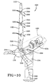
- the present disclosure includes another embodiment of a wind turbine blade system 200 having a plurality of openings 203 disposed on an opening module 205.
- the system 200 includes the arrangement of blade 108, opening module 205 with openings 203 and hub 110 shown and disclosed in FIG. 1 above.
- a controller 605 is present.
- the fluid moving device 207 is mounted at the base of tower 104.
- the fluid flow 209 may travel through the tower 104 and the nacelle 102 prior to being delivered to openings 203.
- the fluid flow 209 may provide cooling to components or equipment in the tower 104 or nacelle 102.
- 10 includes the ability to utilize larger equipment as fluid moving device 207, wherein such fluid moving device 207 does not impose a weight penalty on the turbine.
- the fluid moving device 207 is positioned outside the tower, the size is substantially unrestricted, and substantially without weight penalty.
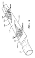
- FIG. 11 shows an exemplary embodiment of a blade 108 having opening modules 205.
- the blade 108 includes a leading edge 1101 and a trailing edge 1103.
- the openings 203 direct fluid, such as air, along a surface of the blade 108 in a direction toward the trailing edge. Fluid flow over the surface of the blade 108 provides effects, such as augmenting aerodynamic lift.
- the opening module 205 and/or the openings 203 may include louvers 1105 to further direct the flow of fluid to provide or alter the aerodynamics of blade 108. Other effects provided by the flow of fluid may be reduced noise or mechanical advantages.
- Other structures may be utilized to direct fluid flow, such as ducts, nozzles, guiding valves, or other fluid directing structures.
- the aerodynamics of particular blade designs may be enhanced or otherwise altered by the direction of fluid flow over or from the surface of blade 108.
- a direction of fluid flow, provided by opening 203 may be selected for a specific radial location and/or specific chordwise location corresponding to the blade design and/or geometry.
- Such selection of fluid flow parameters over the blade may augment the aerodynamic character in a desirable direction (e.g., high lift).
- Such selective flow of fluid may also be configured to reduce or eliminate radial (spanwise) air flow near the root, which is typically counter-productive to making power.
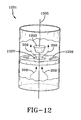
- FIG. 12 shows an exemplary embodiment of a variable blockage device 1201 for placement in fluid conduits or in the interior of blade 108.
- the variable blockage device 1201 includes stopper 1203 mounted on a guide wire 1205.
- the stopper 1203 has a geometry that complements an orifice 1207 in flow restriction plate 1209.
- the variable blockage device 1201 may include, for example, a stopper 1203 fabricated from polymeric material, such as polyurethane, a restriction plate 1209 fabricated from fiberglass and a guide wire 1205 fabricated from plastic, rubber or other suitable material.
- the variable blockage device 1201 may allow fluid flow 209 to move stopper 1203 to a position along guide wire 1205 to permit passage of fluid flow.
- the stopper 1203 is mounted on guide wire 1205, but is permitted to slide along guide wire 1205 substantially along its axis.
- the stopper 1203 may be affixed to the guide wire 1205 and the guide wire may be actuated or otherwise moved, for example, on an elastically deformable wire, to engage and disengage the stopper 1203 with orifice 1207.
- FIG. 12 shows fluid flow 209 flowing bottom to top (as shown in FIG. 12 ), the fluid flow 209 may also be in the opposite direction. Movement and/or actuation of the stopper 1203 may provide controlled fluid flow 209 wherein the flow may be stopped, slowed or substantially unrestricted.
- the variable blockage device 1201 is not limited to the configuration shown in FIG.
- variable blockage device 1201 may be placed in the interior of blade 108, the variable blockage device may be placed in any location through which fluid is forced, including at the fluid moving device, in conduits or openings 203.
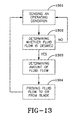
- the present disclosure includes a method for operating a wind turbine.
- the method includes sensing an operating condition for the wind turbine (box 1301).
- the operating condition may include conditions such as, but not limited to, wind speed, mechanical loads, blade position, wind turbine configuration, deflections or other parameters for which a change in blade aerodynamics may be desirable.
- the operating condition may include the blade azimuth position, rotor position, generator condition, or other wind turbine configuration.
- the method further includes determining whether fluid flow is desired (box 1302). This step may be predetermined by the user or may be automatically determined based on the operating conditions. If no fluid flow is desired, the method returns to sensing an operating condition. If fluid flow is desired, the amount of fluid flow is determined (box 1303).
- the rate or amount of fluid flow desired can be determined from a predetermined set of values corresponding to change in system loads or blade deflection as the volumetric flow of fluid delivered to, or extracted from the blade is varied based upon a model system. This relationship can be stored in the controller to determine desired fluid amounts. Utilizing these predetermined values, the particular fluid amount delivered may be a function of the amount of load or deflection change desired in the system at a specific moment in time. The specific amount of fluid determined will also be dependent upon the wind turbine type and wind turbine configuration and may vary between installation locations and/or configurations. In other embodiments, fluid flow may be a simple function of turbine configuration, i.e. the blade azimuth position with respect to the tower. After the amount of fluid flow is determined, the fluid is provided to or from the blade (box 1304). The fluid is provided by the fluid moving device or other suitable method. The controller provides instructions to the fluid moving device or flow restriction devices (e.g. louvers or variable blockage device).
- the fluid moving device or flow restriction devices e.g. louvers
- the present disclosure includes embodiments of controlled fluid delivery to a blade surface utilizing a fluid moving device and/or one or more inlets from which the device receives fluid, and one or more outlets to which the device delivers the fluid.
- the controlled amount of fluid provided to the openings may be provided by altering the power supplied to the fluid moving device to control the volumetric flow rate delivered by the device.
- the mechanical system is configured to meter the fluid mechanically or by altering the operation of the mechanical system.
- fluid movers such as axial flow blowers, may have an inlet vane as part of their design that can be rotated open/closed, thus controlling the amount of fluid.
- Fluid flow at the outlet point may be controlled by flow controlling features such as louvers, which can also alter the flow direction after ejection onto the blade surface (see louvers 1105 illustrated in FIG. 11 ).
- Controlled fluid flow may also be provided by positioning a variable blockage device in conduits guiding the flow, for example a valve.
- a stopper is connected to a guide wire (see FIG. 12 ).
- the wire may be actively controlled, or be influenced by pure centrifugal force.
- Variable blockage devices may be used either before the fluid moving device (upstream), or after the fluid moving device (downstream).
- Controlled fluid flow may include directions the fluid flow, either in whole or in part, to another outlet beside the default outlets.
- This alternate outlet could be located on the blade, but might also be positioned at the hub, nacelle or tower. Having the fluid flow through this alternate outlet may prevent the build-up of pressure within the flow control system when the fluid mover is not switched off while blocking flow through the normal outlets. Redirection to the other outlets can be achieved by actively closing (in whole or in part) the plenum towards the normal outlets while opening the plenum towards the other exit. Alternatively, the plenum towards the alternate outlet is opened, but the plenum towards the normal outlet is unaltered and the fluid flows through both sets of holes.
Landscapes
- Engineering & Computer Science (AREA)
- Mechanical Engineering (AREA)
- Sustainable Development (AREA)
- Sustainable Energy (AREA)
- Chemical & Material Sciences (AREA)
- Combustion & Propulsion (AREA)
- Life Sciences & Earth Sciences (AREA)
- General Engineering & Computer Science (AREA)
- Physics & Mathematics (AREA)
- Fluid Mechanics (AREA)
- Wind Motors (AREA)
- Hydraulic Turbines (AREA)
- Control Of Water Turbines (AREA)
Applications Claiming Priority (1)
| Application Number | Priority Date | Filing Date | Title |
|---|---|---|---|
| US12/612,501 US20110103950A1 (en) | 2009-11-04 | 2009-11-04 | System and method for providing a controlled flow of fluid to or from a wind turbine blade surface |
Publications (2)
| Publication Number | Publication Date |
|---|---|
| EP2320076A2 true EP2320076A2 (fr) | 2011-05-11 |
| EP2320076A3 EP2320076A3 (fr) | 2014-03-19 |
Family
ID=43385733
Family Applications (1)
| Application Number | Title | Priority Date | Filing Date |
|---|---|---|---|
| EP10189247.9A Withdrawn EP2320076A3 (fr) | 2009-11-04 | 2010-10-28 | Système de pale d'éolienne pour fournir un flux contrôlé de fluide provenant de ou envoyé vers une surface de la pale |
Country Status (3)
| Country | Link |
|---|---|
| US (1) | US20110103950A1 (fr) |
| EP (1) | EP2320076A3 (fr) |
| CN (1) | CN102052267A (fr) |
Cited By (11)
| Publication number | Priority date | Publication date | Assignee | Title |
|---|---|---|---|---|
| US9581133B2 (en) | 2011-05-16 | 2017-02-28 | Lm Windpower A/S | Wind turbine blade with noise reduction devices and related method |
| EP2998571B1 (fr) * | 2014-09-19 | 2017-11-01 | Siemens Aktiengesellschaft | Dispositif influençant le levage d'une pale de rotor d'une éolienne |
| WO2018095496A1 (fr) * | 2016-11-24 | 2018-05-31 | Vestas Wind Systems A/S | Améliorations concernant des éoliennes ayant des pales équipées d'un système de contrôle de la couche limite |
| DE102017125415B3 (de) * | 2017-10-30 | 2018-09-06 | clean energy one gmbh | Windenergieanlage mit CO2 Sammler und Windenergieanlagen-CO2-Sammler-Steuerungs- bzw. Betriebsverfahren |
| RU2686816C2 (ru) * | 2017-01-26 | 2019-04-30 | Виктор Михайлович Лятхер | Ортогональный энергетический агрегат |
| EP3480454A4 (fr) * | 2017-09-11 | 2019-05-08 | Beijing Goldwind Science & Creation Windpower Equipment Co. Ltd. | Construction à enceinte extérieure ayant une fonction de suppression de vibration induite par tourbillon, et procédé de suppression de vibration induite par tourbillon |
| IT201900001907A1 (it) * | 2019-02-11 | 2020-08-11 | Daniel Guariglia | Turbina |
| US11920617B2 (en) | 2019-07-23 | 2024-03-05 | Coflow Jet, LLC | Fluid systems and methods that address flow separation |
| US11987352B2 (en) | 2017-10-31 | 2024-05-21 | Coflow Jet, LLC | Fluid systems that include a co-flow jet |
| US12202602B2 (en) | 2020-06-17 | 2025-01-21 | Coflow Jet, LLC | Fluid systems having a variable configuration |
| US12352235B2 (en) | 2021-03-26 | 2025-07-08 | Coflow Jet, LLC | Wind turbine blades and wind turbine systems that include a co-flow jet |
Families Citing this family (26)
| Publication number | Priority date | Publication date | Assignee | Title |
|---|---|---|---|---|
| JP5511549B2 (ja) * | 2010-06-30 | 2014-06-04 | 三菱重工業株式会社 | 風力発電装置 |
| JP5463218B2 (ja) * | 2010-06-30 | 2014-04-09 | 三菱重工業株式会社 | 風力発電装置 |
| DK2450570T3 (da) * | 2010-11-04 | 2013-09-02 | Siemens Ag | Køleindretning til et vindenergianlæg |
| US8246311B2 (en) * | 2010-12-07 | 2012-08-21 | General Electric Company | Wind turbine rotor blade with variably actuatable porous window |
| US8128364B2 (en) * | 2010-12-07 | 2012-03-06 | General Electric Company | Wind turbine rotor blade with porous window and controllable cover member |
| DE102011079432B4 (de) * | 2011-07-19 | 2014-10-23 | Siemens Aktiengesellschaft | Ansteuerung einer Windturbine, Rotorblatt und Windturbine |
| US20130315733A1 (en) * | 2011-11-16 | 2013-11-28 | James E. Smith | Passive thrust enhancement using circulation control |
| US8823199B2 (en) | 2011-11-25 | 2014-09-02 | Rupert Stephen Tull de Salis | Fluid driven turbine |
| US20130136612A1 (en) * | 2011-11-25 | 2013-05-30 | Clean Green Energy LLC | Fluid driven turbine blade, and turbine using same |
| GB2497763A (en) | 2011-12-20 | 2013-06-26 | Ocean Flow Energy Ltd | Air injection system for reducing hydrodynamic loads on water turbine blades |
| CA147876S (en) | 2012-04-11 | 2013-09-27 | Wobben Properties Gmbh | Wind turbine rotor blade |
| USD750560S1 (en) * | 2013-04-11 | 2016-03-01 | Wobben Properties Gmbh | Wind turbine blade |
| EP3115598A4 (fr) * | 2014-03-04 | 2017-03-29 | The Chugoku Electric Power Co., Inc. | Dispositif de production d'énergie éolienne |
| DE102014205016A1 (de) * | 2014-03-18 | 2015-09-24 | Senvion Gmbh | Geräuschreduziertes Rotorblatt einer Windenergieanlage |
| CN104314773A (zh) * | 2014-10-14 | 2015-01-28 | 湖南唯罗克纺织印染机械有限公司 | 一种扭矩输出装置 |
| US20160177922A1 (en) * | 2014-12-22 | 2016-06-23 | Siemens Aktiengesellschaft | Trailing edge jets on wind turbine blade for noise reduction |
| CN107328067A (zh) * | 2017-06-08 | 2017-11-07 | 孔泽学 | 大型清洁造风系统及清洁造风方法 |
| US11660572B2 (en) * | 2017-09-22 | 2023-05-30 | Dehlsen Associates of the Pacific, Limited | Wind and wave desalination vessel |
| US10975732B2 (en) * | 2019-04-04 | 2021-04-13 | General Electric Company | Rotor turning device for balancing a wind turbine rotor |
| EP3798443B1 (fr) * | 2019-09-24 | 2025-01-22 | Wobben Properties GmbH | Éolienne |
| CN110594096B (zh) * | 2019-10-25 | 2021-04-16 | 上海电气风电集团股份有限公司 | 叶片边界层流动控制系统及包括其的风力发电机组 |
| EP3907401A1 (fr) * | 2020-05-05 | 2021-11-10 | Siemens Gamesa Renewable Energy A/S | Dispositif de modification de levage d'une pale de rotor, pale de rotor d'une éolienne et procédé pour modifier le levage d'une pale de rotor |
| EP3957928B1 (fr) * | 2020-08-21 | 2024-02-28 | General Electric Renovables España S.L. | Persiennes et éoliennes comportant de telles persiennes |
| US11549485B1 (en) | 2021-05-04 | 2023-01-10 | Clay Plemmons | Windmill |
| CN113294287B (zh) * | 2021-07-06 | 2025-03-18 | 西安热工研究院有限公司 | 利用压缩空气补风的风力发电系统及其方法 |
| WO2025229391A1 (fr) * | 2024-11-01 | 2025-11-06 | Gamiy Oleg | Aéromoteur |
Family Cites Families (29)
| Publication number | Priority date | Publication date | Assignee | Title |
|---|---|---|---|---|
| WO1999030031A1 (fr) * | 1997-12-08 | 1999-06-17 | Siemens Aktiengesellschaft | Eolienne et procede de refroidissement d'un generateur d'une eolienne |
| DE19802574A1 (de) * | 1998-01-23 | 1999-03-11 | Siemens Ag | Windkraftanlage und Verfahren zum Betrieb einer Windkraftanlage |
| ATE250721T1 (de) * | 1999-07-14 | 2003-10-15 | Aloys Wobben | Windenergieanlage mit einem geschlossenen kühlkreislauf |
| DK174261B1 (da) * | 2000-09-29 | 2002-10-21 | Bonus Energy As | Anordning til brug ved regulering af luftstrømning omkring en vindmøllevinge |
| CA2426711C (fr) * | 2002-05-02 | 2009-11-17 | General Electric Company | Centrale eolienne, mecanisme de commande de centrale eolienne et methode d'exploitation d'une centrale eolienne |
| ITTO20020908A1 (it) * | 2002-10-17 | 2004-04-18 | Lorenzo Battisti | Sistema antighiaccio per impianti eolici. |
| RU2218477C1 (ru) * | 2002-12-30 | 2003-12-10 | ООО "Научно-производственное предприятие "Триумф" | Способ повышения эффективности лопасти ротора ветроэнергетической установки (варианты) |
| US6940185B2 (en) * | 2003-04-10 | 2005-09-06 | Advantek Llc | Advanced aerodynamic control system for a high output wind turbine |
| JP2005069082A (ja) * | 2003-08-22 | 2005-03-17 | Fuji Heavy Ind Ltd | 風車の温度制御装置 |
| US7086834B2 (en) * | 2004-06-10 | 2006-08-08 | General Electric Company | Methods and apparatus for rotor blade ice detection |
| US7217091B2 (en) * | 2004-07-20 | 2007-05-15 | General Electric Company | Methods and apparatus for deicing airfoils or rotor blades |
| DE102004064007B4 (de) * | 2004-09-24 | 2009-08-20 | Aloys Wobben | Windenergieanlage mit einer Generatorkühlung |
| US7320575B2 (en) * | 2004-09-28 | 2008-01-22 | General Electric Company | Methods and apparatus for aerodynamically self-enhancing rotor blades |
| US7387491B2 (en) * | 2004-12-23 | 2008-06-17 | General Electric Company | Active flow modifications on wind turbine blades |
| US7435057B2 (en) * | 2005-07-13 | 2008-10-14 | Jorge Parera | Blade for wind turbine |
| US20070231151A1 (en) * | 2005-10-10 | 2007-10-04 | General Electric Company | Active flow control for wind turbine blades |
| US7354247B2 (en) * | 2005-10-27 | 2008-04-08 | General Electric Company | Blade for a rotor of a wind energy turbine |
| EP2122164B1 (fr) * | 2007-01-05 | 2016-03-23 | LM WP Patent Holding A/S | Pale d'éolienne avec moyens de régulation de portance sous la forme de fentes ou de trous |
| US7909575B2 (en) * | 2007-06-25 | 2011-03-22 | General Electric Company | Power loss reduction in turbulent wind for a wind turbine using localized sensing and control |
| DE602007013566D1 (de) * | 2007-10-22 | 2011-05-12 | Actiflow B V | Windenergieanlage mit Grenzschichtsteuerung |
| JP4796039B2 (ja) * | 2007-11-22 | 2011-10-19 | 三菱重工業株式会社 | 風力発電装置 |
| US8376704B2 (en) * | 2009-11-05 | 2013-02-19 | General Electric Company | Systems and method of assembling an air distribution system for use in a rotor blade of a wind turbine |
| US8321062B2 (en) * | 2009-11-05 | 2012-11-27 | General Electric Company | Systems and method for operating a wind turbine having active flow control |
| US8221075B2 (en) * | 2009-11-05 | 2012-07-17 | General Electric Company | Systems and method for operating a wind turbine having active flow control |
| US7883313B2 (en) * | 2009-11-05 | 2011-02-08 | General Electric Company | Active flow control system for wind turbine |
| US8047783B2 (en) * | 2009-11-05 | 2011-11-01 | General Electric Company | Systems and method for operating an active flow control system |
| US8475129B2 (en) * | 2009-12-10 | 2013-07-02 | General Electric Company | Systems and methods for assembling an air distribution system for use in a rotor blade of a wind turbine |
| JP5511549B2 (ja) * | 2010-06-30 | 2014-06-04 | 三菱重工業株式会社 | 風力発電装置 |
| US8267653B2 (en) * | 2010-12-21 | 2012-09-18 | General Electric Company | System and method of operating an active flow control system to manipulate a boundary layer across a rotor blade of a wind turbine |
-
2009
- 2009-11-04 US US12/612,501 patent/US20110103950A1/en not_active Abandoned
-
2010
- 2010-10-28 EP EP10189247.9A patent/EP2320076A3/fr not_active Withdrawn
- 2010-11-04 CN CN2010105451818A patent/CN102052267A/zh active Pending
Non-Patent Citations (1)
| Title |
|---|
| None |
Cited By (17)
| Publication number | Priority date | Publication date | Assignee | Title |
|---|---|---|---|---|
| US9581133B2 (en) | 2011-05-16 | 2017-02-28 | Lm Windpower A/S | Wind turbine blade with noise reduction devices and related method |
| US10408192B2 (en) | 2014-09-19 | 2019-09-10 | Siemens Gamesa Renewable Energy A/S | Lift influencing device for a rotor blade of a wind turbine |
| EP2998571B1 (fr) * | 2014-09-19 | 2017-11-01 | Siemens Aktiengesellschaft | Dispositif influençant le levage d'une pale de rotor d'une éolienne |
| WO2018095496A1 (fr) * | 2016-11-24 | 2018-05-31 | Vestas Wind Systems A/S | Améliorations concernant des éoliennes ayant des pales équipées d'un système de contrôle de la couche limite |
| US11248584B2 (en) | 2016-11-24 | 2022-02-15 | Vestas Wind Systems A/S | Relating to wind turbines having blades equipped with boundary layer control system |
| RU2686816C2 (ru) * | 2017-01-26 | 2019-04-30 | Виктор Михайлович Лятхер | Ортогональный энергетический агрегат |
| US11506180B2 (en) * | 2017-09-11 | 2022-11-22 | Beijing Goldwind Science & Creation Windpower Equipment Co.. Ltd. | Enclosure with vortex-induced vibration suppression function and method for suppressing vortex-induced vibration |
| EP3480454A4 (fr) * | 2017-09-11 | 2019-05-08 | Beijing Goldwind Science & Creation Windpower Equipment Co. Ltd. | Construction à enceinte extérieure ayant une fonction de suppression de vibration induite par tourbillon, et procédé de suppression de vibration induite par tourbillon |
| WO2019086069A1 (fr) | 2017-10-30 | 2019-05-09 | clean energy one gmbh | Aérogénérateur avec collecteur de co2 et procédé de commande ou de fonctionnement de collecteur de co2 d'aérogénérateur |
| DE102017125415B8 (de) * | 2017-10-30 | 2018-10-25 | clean energy one gmbh | Windenergieanlage mit CO2 Sammler und Windenergieanlagen-CO2-Sammler-Steuerungs- bzw. Betriebsverfahren |
| DE102017125415B3 (de) * | 2017-10-30 | 2018-09-06 | clean energy one gmbh | Windenergieanlage mit CO2 Sammler und Windenergieanlagen-CO2-Sammler-Steuerungs- bzw. Betriebsverfahren |
| US11987352B2 (en) | 2017-10-31 | 2024-05-21 | Coflow Jet, LLC | Fluid systems that include a co-flow jet |
| IT201900001907A1 (it) * | 2019-02-11 | 2020-08-11 | Daniel Guariglia | Turbina |
| WO2020165663A1 (fr) * | 2019-02-11 | 2020-08-20 | Guariglia Daniel | Éolienne |
| US11920617B2 (en) | 2019-07-23 | 2024-03-05 | Coflow Jet, LLC | Fluid systems and methods that address flow separation |
| US12202602B2 (en) | 2020-06-17 | 2025-01-21 | Coflow Jet, LLC | Fluid systems having a variable configuration |
| US12352235B2 (en) | 2021-03-26 | 2025-07-08 | Coflow Jet, LLC | Wind turbine blades and wind turbine systems that include a co-flow jet |
Also Published As
| Publication number | Publication date |
|---|---|
| EP2320076A3 (fr) | 2014-03-19 |
| CN102052267A (zh) | 2011-05-11 |
| US20110103950A1 (en) | 2011-05-05 |
Similar Documents
| Publication | Publication Date | Title |
|---|---|---|
| EP2320076A2 (fr) | Système de pale d'éolienne pour fournir un flux contrôlé de fluide provenant de ou envoyé vers une surface de la pale | |
| EP1780408B1 (fr) | Pale de rotor pour une éolienne | |
| US10024300B2 (en) | Turbine blades and systems with forward blowing slots | |
| US7112034B2 (en) | Wind turbine assembly | |
| US20070014657A1 (en) | Blade for wind turbine | |
| US20100209236A1 (en) | Impulse turbine for use in bi-directional flows | |
| US20100296913A1 (en) | Wind power generating system with vertical axis jet wheel turbine | |
| US20110206531A1 (en) | Efficient low-cost wind energy using passive circulation control | |
| US20150056074A1 (en) | System and method for deicing wind turbine rotor blades | |
| CN101438054A (zh) | 多涡轮气流增强发生器 | |
| KR20140040714A (ko) | 디퓨저 부착형 풍력 터빈 | |
| KR20140040713A (ko) | 디퓨저 부착형 풍력 터빈 | |
| EP4083413B1 (fr) | Alimentation de secours pour éoliennes | |
| CN104169574A (zh) | 涡轮机 | |
| JP2012530210A (ja) | 圧力制御風力タービン強化システム | |
| US20140030059A1 (en) | Fluid turbine with variable pitch shroud segments | |
| WO2023287431A1 (fr) | Pale de rotor d'éolienne dotée d'un ensemble de modification d'écoulement d'air passif | |
| CN210290004U (zh) | 风轮机、压缩机及发电机 | |
| CN101603510A (zh) | 带抽气装置的聚风增速型风力发电机 | |
| CN112703314B (zh) | 具有带空气动力学特性的叶片承载结构的风力涡轮机 | |
| CN206299513U (zh) | 一种以气流推力增强变桨能力的风机叶片 | |
| EP3847368A1 (fr) | Structure de turbine fluidique | |
| DK201470503A1 (en) | System and method for deicing wind turbine rotor blades | |
| US12203441B1 (en) | Fluid turbine configured for moment-arm and thrust-force load control | |
| CN115398097A (zh) | 环形升力发动机 |
Legal Events
| Date | Code | Title | Description |
|---|---|---|---|
| PUAI | Public reference made under article 153(3) epc to a published international application that has entered the european phase |
Free format text: ORIGINAL CODE: 0009012 |
|
| AK | Designated contracting states |
Kind code of ref document: A2 Designated state(s): AL AT BE BG CH CY CZ DE DK EE ES FI FR GB GR HR HU IE IS IT LI LT LU LV MC MK MT NL NO PL PT RO RS SE SI SK SM TR |
|
| AX | Request for extension of the european patent |
Extension state: BA ME |
|
| PUAL | Search report despatched |
Free format text: ORIGINAL CODE: 0009013 |
|
| AK | Designated contracting states |
Kind code of ref document: A3 Designated state(s): AL AT BE BG CH CY CZ DE DK EE ES FI FR GB GR HR HU IE IS IT LI LT LU LV MC MK MT NL NO PL PT RO RS SE SI SK SM TR |
|
| AX | Request for extension of the european patent |
Extension state: BA ME |
|
| RIC1 | Information provided on ipc code assigned before grant |
Ipc: F03D 7/02 20060101ALI20140213BHEP Ipc: F03D 11/02 20060101ALI20140213BHEP Ipc: F03D 1/06 20060101AFI20140213BHEP |
|
| STAA | Information on the status of an ep patent application or granted ep patent |
Free format text: STATUS: THE APPLICATION IS DEEMED TO BE WITHDRAWN |
|
| 18D | Application deemed to be withdrawn |
Effective date: 20140501 |
|
| P01 | Opt-out of the competence of the unified patent court (upc) registered |
Effective date: 20230522 |