EP2320090A2 - Pompe à vide poussé - Google Patents
Pompe à vide poussé Download PDFInfo
- Publication number
- EP2320090A2 EP2320090A2 EP10013671A EP10013671A EP2320090A2 EP 2320090 A2 EP2320090 A2 EP 2320090A2 EP 10013671 A EP10013671 A EP 10013671A EP 10013671 A EP10013671 A EP 10013671A EP 2320090 A2 EP2320090 A2 EP 2320090A2
- Authority
- EP
- European Patent Office
- Prior art keywords
- lubricant
- rotor
- vacuum pump
- high vacuum
- stator
- Prior art date
- Legal status (The legal status is an assumption and is not a legal conclusion. Google has not performed a legal analysis and makes no representation as to the accuracy of the status listed.)
- Granted
Links
Images


Classifications
-
- F—MECHANICAL ENGINEERING; LIGHTING; HEATING; WEAPONS; BLASTING
- F04—POSITIVE - DISPLACEMENT MACHINES FOR LIQUIDS; PUMPS FOR LIQUIDS OR ELASTIC FLUIDS
- F04D—NON-POSITIVE-DISPLACEMENT PUMPS
- F04D19/00—Axial-flow pumps
- F04D19/02—Multi-stage pumps
- F04D19/04—Multi-stage pumps specially adapted to the production of a high vacuum, e.g. molecular pumps
- F04D19/042—Turbomolecular vacuum pumps
-
- F—MECHANICAL ENGINEERING; LIGHTING; HEATING; WEAPONS; BLASTING
- F04—POSITIVE - DISPLACEMENT MACHINES FOR LIQUIDS; PUMPS FOR LIQUIDS OR ELASTIC FLUIDS
- F04D—NON-POSITIVE-DISPLACEMENT PUMPS
- F04D17/00—Radial-flow pumps, e.g. centrifugal pumps; Helico-centrifugal pumps
- F04D17/08—Centrifugal pumps
- F04D17/16—Centrifugal pumps for displacing without appreciable compression
- F04D17/168—Pumps specially adapted to produce a vacuum
-
- F—MECHANICAL ENGINEERING; LIGHTING; HEATING; WEAPONS; BLASTING
- F04—POSITIVE - DISPLACEMENT MACHINES FOR LIQUIDS; PUMPS FOR LIQUIDS OR ELASTIC FLUIDS
- F04D—NON-POSITIVE-DISPLACEMENT PUMPS
- F04D27/00—Control, e.g. regulation, of pumps, pumping installations or pumping systems specially adapted for elastic fluids
- F04D27/02—Surge control
- F04D27/0292—Stop safety or alarm devices, e.g. stop-and-go control; Disposition of check-valves
-
- F—MECHANICAL ENGINEERING; LIGHTING; HEATING; WEAPONS; BLASTING
- F04—POSITIVE - DISPLACEMENT MACHINES FOR LIQUIDS; PUMPS FOR LIQUIDS OR ELASTIC FLUIDS
- F04D—NON-POSITIVE-DISPLACEMENT PUMPS
- F04D29/00—Details, component parts, or accessories
- F04D29/05—Shafts or bearings, or assemblies thereof, specially adapted for elastic fluid pumps
- F04D29/056—Bearings
- F04D29/059—Roller bearings
-
- F—MECHANICAL ENGINEERING; LIGHTING; HEATING; WEAPONS; BLASTING
- F04—POSITIVE - DISPLACEMENT MACHINES FOR LIQUIDS; PUMPS FOR LIQUIDS OR ELASTIC FLUIDS
- F04D—NON-POSITIVE-DISPLACEMENT PUMPS
- F04D29/00—Details, component parts, or accessories
- F04D29/06—Lubrication
- F04D29/063—Lubrication specially adapted for elastic fluid pumps
Definitions
- the invention relates to a high vacuum pump according to the preamble of the first claim.
- Vacuum pumps of molecular and turbomolecular design have proven to produce high vacuum.
- a generic vacuum pump has a fast rotating rotor that rotates at tens of thousands of revolutions per minute.
- Various types of storage are known, including non-contact magnetic bearings and bearings, such as ball bearings with oil or grease lubrication and ceramic balls. These known bearings lead to an electrically insulated suspension of the rotor, so that it can come to a charging of the rotor with appropriate fluids to be pumped.
- uncontrolled electrical discharge, so-called flashovers, between rotor and stator which lead to mechanical damage to these components and are therefore undesirable.
- the EP-A 1915512 Suggests two solutions to this problem.
- the first solution provides a filamentous and conductive body contacting the rotor.
- the second solution is to generate by geometric design at a specific location flashovers between the rotor and stator.
- the first solution is disadvantageous in that the body and its contacting point on the rotor are subject to wear due to the contact which occurs even at a low relative speed. The abrasion generated by this wear accumulates in the ball bearing and destroys it.
- the second solution has the disadvantage that the component to which the flashovers take place, erosion damage occur. This erosion means wear, so that the arrangement lacks long-term stability. After some time, the arrangement does not work anymore and uncontrolled flashovers occur again.
- the means for lubricating the rolling bearing are adapted such that such a discharge of the rotor is caused to prevent flashovers between the rotor and the stator. Damage to the rotor and stator is thus prevented. Since the already existing means for lubricating the bearing are adjusted and used, this is done advantageously without the use of other components. This is inexpensive and avoids mistakes. In addition, this solution is very low wear compared to the prior art and allows long service life.
- a further embodiment provides that a conductive feed wick is used. In addition to the advantages mentioned above, this is advantageous because a lasting good discharge due to the constant contact is effected.
- Another embodiment provides to use a conductive lubricant. This is a virtually completely wear-free solution.
- the conductive lubricant comprises carbon nanotubes.
- the addition of these carbon nanotubes causes a well-defined in the sense of the claim formulated to claim 1 sufficiently good conductivity, without a deterioration of the essential properties for use in a high vacuum pump properties of the lubricant occurs.
- the means is designed as a lubricant circuit. This improves the discharge of the rotor, since an additional transport takes place. This solution is also advantageous in a vibration-decoupled mounting of the rolling bearing in elastomeric bodies, since the discharge via the lubricant circuit and not interrupted by the elastomer body contact from outer ring to housing of the high vacuum pump of the bearing.
- FIG Fig. 1 A section through a high vacuum pump 100 is shown in FIG Fig. 1 shown.
- the high vacuum pump has a housing 102 which has a flange 104 and which allows releasable attachment to a container to be evacuated.
- the flange defines the gas inlet 106.
- the housing surrounds the components of the stator 120, which includes a bladed stator disk 122 and a spacer 124. Depending on requirements such as pumping speed and compression, the number of stator disks is dimensioned.
- other molecular pumping principles can be used, for example, according to the Holweck, Siegbahn and 9.kanal principle.
- the stator cooperates with the rotor 110, which includes a bladed rotor disk 114 and a shaft 112.
- the number of rotor disks mounted on the shaft corresponds to the number of stator disks.
- the rotor may also include other pump-active elements that interact with stator elements, such as a Holweck cylinder.
- a motor coil 128 is disposed in the housing and puts the shaft and thus the rotor in rapid rotation.
- the shaft is rotatably supported by a permanent magnetic bearing 126.
- the gas inlet remote end of the shaft is supported by a bearing assembly 170.
- the bearing assembly comprises a roller bearing 130, which in this example is designed as a grease-lubricated ball bearing.
- a roller bearing 130 On the shaft sits the inner ring 134 of the ball bearing, the outer ring 132 is supported by means of a Axialschwingringes 140 and a Radialschwingringes 142 in the axial and radial directions swingable in the housing.
- Axialschwingring and Radialschwingring are designed as electrically non-conductive elastomer rings.
- Between inner ring and outer ring balls 136 are arranged as rolling elements.
- a cover plate 144 closes the space between the inner ring and outer ring and holds the lubricant reservoir 144 in the rolling bearing.
- the lubricant supply contains the grease as a lubricant and is designed as a lifetime lubrication.
- the described type of bearing with contact-free permanent magnet bearing and roller bearings causes, especially when ceramic balls are used in the rolling bearing, a good electrical insulation of the rotor relative to the stator.
- the insulation is removed, in which a conductive grease is used in the lubricant supply.
- the electrical charging of the rotor is prevented because it is earthed via the rolling bearing and the grease.
- either axial or radial ring or both may be made of electrically conductive material, such as an embedded conductive material elastomer.
- an electrical conductor may be provided between the outer ring and the housing.
- Both fat and axial and radial resonant rings can be loaded with carbon nanotubes for improved electrical conductivity.
- the achieved conductivity must only be so dimensioned that the charging of the rotor is so low that the field strengths between rotor and stator reach no value that allows discharge by flashover or sparks.
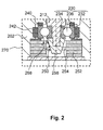
- the Fig. 2 shows a section through the bearing assembly of the high vacuum pump in an alternative embodiment.
- This alternative bearing arrangement 270 comprises a ball bearing 230 whose inner ring 234 is fixed on the shaft 212.
- the outer ring 232 is oscillatable by means of a Axialschwingrings 240 and a Radialschwingrings 242 Housing 202 is supported. Between the inner ring and outer ring are the balls 236.
- the lubrication takes place through a lubricant circuit 268. This is in Fig. 2 illustrated by arrows. Part of this lubricant circuit is the lubricant reservoir 252. It has at least one supply wick 250 which is in sliding contact with a conically shaped and arranged on the shaft spray nut 256.
- the lubricant 250 shown by dots is transferred from the lubricant reservoir to the spray nut. About the centrifugal force, the lubricant is conveyed along the cone in the space between the bearing inner ring and bearing outer ring and there causes the lubrication. The lubricant falls from the intermediate space back into the lubricant reservoir and can be re-supplied to the ball bearing there by capillary action via the feed wick in the next circulation of the lubricant circuit.
- grounding of the rotor via the means for lubricating the ball bearing can be done via two alternative ways, whereby both ways can be realized simultaneously.
- the lubricant itself can be made conductive. This is achieved by the addition of conductive substances to lubricants, such as graphite. Carbon nanotubes prove to be particularly advantageous. Lubricant circulation and filling of the lubricant reservoir then cause a conductive connection from shaft to housing. The charging of the rotor is thereby kept so low that there is no electrical discharge or spark between the rotor and stator.
- the feed wick can be made of conductive material.
- Feed wick and lubricant reservoir comprise a felt-like material which stores the lubricant in its pores and promotes it via capillary action. Electrical conductivity is sufficiently effected by admixture of metallic fibers or conductive carbon fiber.
- the Fig. 3 shows a section through the bearing assembly of the high vacuum pump in a third embodiment.
- the bearing assembly 370 has a ball bearing 330. Its inner ring 334 is fixed on the shaft 312. Its outer ring 332 is supported in the housing 302 by means of an axial oscillating ring 340 and a radial oscillating ring 342 in the axial and radial directions.
- a lubricant-containing lubricant circuit 368 is provided, which in Fig. 3 is illustrated by arrows.
- the lubricant circuit comprises a lubricant pump 352, which contains the lubricant 350, which in Fig. 3 is illustrated by dots through which feed channel 360 feeds into a feed nozzle 362.
- the lubricant is conveyed to the conically shaped spray nut 356.
- the lubricant is conveyed by the centrifugal force along the cone in the ball bearing. From there it enters the drainage channel 364 and through this back into the lubricant pump.
- the adaptation of the means for lubricating the ball bearing in this example is to carry out the lubricant itself conductive. This is achieved in an advantageous variant via the addition of carbon nanotubes.
- the lubricant circuit then causes a conductive connection from shaft to housing. As a result, the charging of the rotor is kept so low that none of the electrical discharges occurring between the rotor and the stator occur in the prior art.
Landscapes
- Engineering & Computer Science (AREA)
- Mechanical Engineering (AREA)
- General Engineering & Computer Science (AREA)
- Non-Positive Displacement Air Blowers (AREA)
Applications Claiming Priority (1)
| Application Number | Priority Date | Filing Date | Title |
|---|---|---|---|
| DE200910052180 DE102009052180A1 (de) | 2009-11-06 | 2009-11-06 | Hochvakuumpumpe |
Publications (3)
| Publication Number | Publication Date |
|---|---|
| EP2320090A2 true EP2320090A2 (fr) | 2011-05-11 |
| EP2320090A3 EP2320090A3 (fr) | 2017-06-07 |
| EP2320090B1 EP2320090B1 (fr) | 2019-02-20 |
Family
ID=43500019
Family Applications (1)
| Application Number | Title | Priority Date | Filing Date |
|---|---|---|---|
| EP10013671.2A Not-in-force EP2320090B1 (fr) | 2009-11-06 | 2010-10-15 | Pompe à vide poussé |
Country Status (2)
| Country | Link |
|---|---|
| EP (1) | EP2320090B1 (fr) |
| DE (1) | DE102009052180A1 (fr) |
Cited By (2)
| Publication number | Priority date | Publication date | Assignee | Title |
|---|---|---|---|---|
| EP2808549A1 (fr) * | 2013-05-29 | 2014-12-03 | Pfeiffer Vacuum Gmbh | Pompe à vide |
| CN108678975A (zh) * | 2018-07-17 | 2018-10-19 | 中国工程物理研究院机械制造工艺研究所 | 一种抗振动分子泵 |
Families Citing this family (3)
| Publication number | Priority date | Publication date | Assignee | Title |
|---|---|---|---|---|
| DE102011109930A1 (de) * | 2011-08-10 | 2013-02-14 | Pfeiffer Vacuum Gmbh | Wälzlager und Vakuumpumpe mit Wälzlager |
| DE102011119907A1 (de) * | 2011-12-01 | 2013-06-06 | Pfeiffer Vacuum Gmbh | Wälzlager für eine Vakuumpumpe |
| EP3594498B1 (fr) | 2019-11-06 | 2022-01-05 | Pfeiffer Vacuum Gmbh | Système avec un dispositif de recyclage des gaz |
Citations (1)
| Publication number | Priority date | Publication date | Assignee | Title |
|---|---|---|---|---|
| EP1915512A2 (fr) | 2005-08-16 | 2008-04-30 | Edwards Vacuum, Inc. | Pompe turbomoleculaire a commande de charge statique |
Family Cites Families (3)
| Publication number | Priority date | Publication date | Assignee | Title |
|---|---|---|---|---|
| DE10037423A1 (de) * | 2000-07-21 | 2002-02-07 | Atecs Mannesmann Ag | Wälzlageranordnung für einen Elektromotor (stromisoliertes Wälzlager |
| DE102006053237A1 (de) * | 2006-11-11 | 2008-05-29 | Pfeiffer Vacuum Gmbh | Lagermodul für eine Vakuumpumpe |
| GB0712777D0 (en) * | 2007-07-02 | 2007-08-08 | Edwards Ltd | Vacuum Pump |
-
2009
- 2009-11-06 DE DE200910052180 patent/DE102009052180A1/de not_active Ceased
-
2010
- 2010-10-15 EP EP10013671.2A patent/EP2320090B1/fr not_active Not-in-force
Patent Citations (1)
| Publication number | Priority date | Publication date | Assignee | Title |
|---|---|---|---|---|
| EP1915512A2 (fr) | 2005-08-16 | 2008-04-30 | Edwards Vacuum, Inc. | Pompe turbomoleculaire a commande de charge statique |
Cited By (5)
| Publication number | Priority date | Publication date | Assignee | Title |
|---|---|---|---|---|
| EP2808549A1 (fr) * | 2013-05-29 | 2014-12-03 | Pfeiffer Vacuum Gmbh | Pompe à vide |
| JP2014231835A (ja) * | 2013-05-29 | 2014-12-11 | プファイファー・ヴァキューム・ゲーエムベーハー | 真空ポンプ |
| CN104214112A (zh) * | 2013-05-29 | 2014-12-17 | 普发真空有限公司 | 真空泵 |
| CN104214112B (zh) * | 2013-05-29 | 2017-08-25 | 普发真空有限公司 | 真空泵 |
| CN108678975A (zh) * | 2018-07-17 | 2018-10-19 | 中国工程物理研究院机械制造工艺研究所 | 一种抗振动分子泵 |
Also Published As
| Publication number | Publication date |
|---|---|
| DE102009052180A1 (de) | 2011-05-12 |
| EP2320090A3 (fr) | 2017-06-07 |
| EP2320090B1 (fr) | 2019-02-20 |
Similar Documents
| Publication | Publication Date | Title |
|---|---|---|
| DE102007014142B4 (de) | Vakuumpumpe | |
| EP1921322B1 (fr) | Module du palier pour une pompe à vide | |
| EP1301978B1 (fr) | Systeme de palier a roulement pour un moteur electrique | |
| EP2320090B1 (fr) | Pompe à vide poussé | |
| EP2060794B1 (fr) | Pompe à vide dotée d'une pompe à lubrifiant | |
| EP2557316B1 (fr) | Pompe à vide | |
| DE102010021945A1 (de) | Vakuumpumpe | |
| EP1719916B1 (fr) | Groupe motopompe | |
| DE102011119907A1 (de) | Wälzlager für eine Vakuumpumpe | |
| DE102018123909B4 (de) | Kompakt-Gleitlager mit Dichtungsanordnung und Wasserpumpe mit demselben | |
| DE102015101876B4 (de) | Kontaktier-Anordnung zum elektrischen Kontaktieren einer drehbar gelagerten Welle und Lageranordnung zum drehbaren Lagern einer Elektrode | |
| DE69912680T2 (de) | Kompakte Vakuumpumpe | |
| DE102018218432B4 (de) | Drehanodenlagerung für eine Röntgenröhre und Drehanode für eine Röntgenröhre | |
| DE102018216966A1 (de) | Elektromotor mit geerdeter Welle | |
| EP3650702B1 (fr) | Utilisation d'une huile synthétique dans une pompe à vide et pompe à vide | |
| DE102015100048B4 (de) | Anordnung zur Lagerung einer Welle einer Vakuumpumpe | |
| DE102005021354A1 (de) | Anordung zum Begrenzen von Überspannungen an Funktionsteilen umrichtergespeister elektrischer Maschinen | |
| DE102023201167A1 (de) | Elektrische Maschine mit einer leitenden Hülse | |
| EP3184835A1 (fr) | Palier de securité | |
| DE2201399A1 (de) | Schmieranordnung fuer die schmierung eines lagers | |
| DE102016209581A1 (de) | Kontaktanordnung für eine elektrische Maschine | |
| DE102023121997A1 (de) | Bypass-Vorrichtung, Wälzlager mit einer Bypass-Vorrichtung sowie Verfahren zur Ableitung elektrostatischer Ladungen an einem Wälzlager | |
| WO2009121511A1 (fr) | Palier avec bague rotative mise à la terre | |
| WO2025103624A1 (fr) | Dispositif parafoudre, atomiseur rotatif comprenant un tel dispositif parafoudre, utilisation d'un tel dispositif parafoudre | |
| WO2021204472A1 (fr) | Pompe à eau présentant une construction optimisée pour application |
Legal Events
| Date | Code | Title | Description |
|---|---|---|---|
| PUAI | Public reference made under article 153(3) epc to a published international application that has entered the european phase |
Free format text: ORIGINAL CODE: 0009012 |
|
| AK | Designated contracting states |
Kind code of ref document: A2 Designated state(s): AL AT BE BG CH CY CZ DE DK EE ES FI FR GB GR HR HU IE IS IT LI LT LU LV MC MK MT NL NO PL PT RO RS SE SI SK SM TR |
|
| AX | Request for extension of the european patent |
Extension state: BA ME |
|
| PUAL | Search report despatched |
Free format text: ORIGINAL CODE: 0009013 |
|
| STAA | Information on the status of an ep patent application or granted ep patent |
Free format text: STATUS: REQUEST FOR EXAMINATION WAS MADE |
|
| AK | Designated contracting states |
Kind code of ref document: A3 Designated state(s): AL AT BE BG CH CY CZ DE DK EE ES FI FR GB GR HR HU IE IS IT LI LT LU LV MC MK MT NL NO PL PT RO RS SE SI SK SM TR |
|
| AX | Request for extension of the european patent |
Extension state: BA ME |
|
| RIC1 | Information provided on ipc code assigned before grant |
Ipc: F04D 29/063 20060101ALI20170428BHEP Ipc: F04D 17/16 20060101AFI20170428BHEP Ipc: F04D 29/059 20060101ALI20170428BHEP Ipc: F04D 27/02 20060101ALI20170428BHEP Ipc: F04D 19/04 20060101ALI20170428BHEP |
|
| PUAL | Search report despatched |
Free format text: ORIGINAL CODE: 0009013 |
|
| 17P | Request for examination filed |
Effective date: 20170524 |
|
| RBV | Designated contracting states (corrected) |
Designated state(s): AL AT BE BG CH CY CZ DE DK EE ES FI FR GB GR HR HU IE IS IT LI LT LU LV MC MK MT NL NO PL PT RO RS SE SI SK SM TR |
|
| STAA | Information on the status of an ep patent application or granted ep patent |
Free format text: STATUS: EXAMINATION IS IN PROGRESS |
|
| 17Q | First examination report despatched |
Effective date: 20180703 |
|
| GRAP | Despatch of communication of intention to grant a patent |
Free format text: ORIGINAL CODE: EPIDOSNIGR1 |
|
| STAA | Information on the status of an ep patent application or granted ep patent |
Free format text: STATUS: GRANT OF PATENT IS INTENDED |
|
| INTG | Intention to grant announced |
Effective date: 20180829 |
|
| GRAS | Grant fee paid |
Free format text: ORIGINAL CODE: EPIDOSNIGR3 |
|
| GRAA | (expected) grant |
Free format text: ORIGINAL CODE: 0009210 |
|
| STAA | Information on the status of an ep patent application or granted ep patent |
Free format text: STATUS: THE PATENT HAS BEEN GRANTED |
|
| AK | Designated contracting states |
Kind code of ref document: B1 Designated state(s): AL AT BE BG CH CY CZ DE DK EE ES FI FR GB GR HR HU IE IS IT LI LT LU LV MC MK MT NL NO PL PT RO RS SE SI SK SM TR |
|
| REG | Reference to a national code |
Ref country code: GB Ref legal event code: FG4D Free format text: NOT ENGLISH |
|
| REG | Reference to a national code |
Ref country code: CH Ref legal event code: EP |
|
| REG | Reference to a national code |
Ref country code: DE Ref legal event code: R096 Ref document number: 502010015784 Country of ref document: DE |
|
| REG | Reference to a national code |
Ref country code: AT Ref legal event code: REF Ref document number: 1098548 Country of ref document: AT Kind code of ref document: T Effective date: 20190315 |
|
| REG | Reference to a national code |
Ref country code: IE Ref legal event code: FG4D Free format text: LANGUAGE OF EP DOCUMENT: GERMAN |
|
| REG | Reference to a national code |
Ref country code: LT Ref legal event code: MG4D Ref country code: NL Ref legal event code: MP Effective date: 20190220 |
|
| PG25 | Lapsed in a contracting state [announced via postgrant information from national office to epo] |
Ref country code: NO Free format text: LAPSE BECAUSE OF FAILURE TO SUBMIT A TRANSLATION OF THE DESCRIPTION OR TO PAY THE FEE WITHIN THE PRESCRIBED TIME-LIMIT Effective date: 20190520 Ref country code: FI Free format text: LAPSE BECAUSE OF FAILURE TO SUBMIT A TRANSLATION OF THE DESCRIPTION OR TO PAY THE FEE WITHIN THE PRESCRIBED TIME-LIMIT Effective date: 20190220 Ref country code: PT Free format text: LAPSE BECAUSE OF FAILURE TO SUBMIT A TRANSLATION OF THE DESCRIPTION OR TO PAY THE FEE WITHIN THE PRESCRIBED TIME-LIMIT Effective date: 20190620 Ref country code: SE Free format text: LAPSE BECAUSE OF FAILURE TO SUBMIT A TRANSLATION OF THE DESCRIPTION OR TO PAY THE FEE WITHIN THE PRESCRIBED TIME-LIMIT Effective date: 20190220 Ref country code: LT Free format text: LAPSE BECAUSE OF FAILURE TO SUBMIT A TRANSLATION OF THE DESCRIPTION OR TO PAY THE FEE WITHIN THE PRESCRIBED TIME-LIMIT Effective date: 20190220 |
|
| PG25 | Lapsed in a contracting state [announced via postgrant information from national office to epo] |
Ref country code: NL Free format text: LAPSE BECAUSE OF FAILURE TO SUBMIT A TRANSLATION OF THE DESCRIPTION OR TO PAY THE FEE WITHIN THE PRESCRIBED TIME-LIMIT Effective date: 20190220 Ref country code: LV Free format text: LAPSE BECAUSE OF FAILURE TO SUBMIT A TRANSLATION OF THE DESCRIPTION OR TO PAY THE FEE WITHIN THE PRESCRIBED TIME-LIMIT Effective date: 20190220 Ref country code: HR Free format text: LAPSE BECAUSE OF FAILURE TO SUBMIT A TRANSLATION OF THE DESCRIPTION OR TO PAY THE FEE WITHIN THE PRESCRIBED TIME-LIMIT Effective date: 20190220 Ref country code: GR Free format text: LAPSE BECAUSE OF FAILURE TO SUBMIT A TRANSLATION OF THE DESCRIPTION OR TO PAY THE FEE WITHIN THE PRESCRIBED TIME-LIMIT Effective date: 20190521 Ref country code: IS Free format text: LAPSE BECAUSE OF FAILURE TO SUBMIT A TRANSLATION OF THE DESCRIPTION OR TO PAY THE FEE WITHIN THE PRESCRIBED TIME-LIMIT Effective date: 20190620 Ref country code: RS Free format text: LAPSE BECAUSE OF FAILURE TO SUBMIT A TRANSLATION OF THE DESCRIPTION OR TO PAY THE FEE WITHIN THE PRESCRIBED TIME-LIMIT Effective date: 20190220 Ref country code: BG Free format text: LAPSE BECAUSE OF FAILURE TO SUBMIT A TRANSLATION OF THE DESCRIPTION OR TO PAY THE FEE WITHIN THE PRESCRIBED TIME-LIMIT Effective date: 20190520 |
|
| PG25 | Lapsed in a contracting state [announced via postgrant information from national office to epo] |
Ref country code: ES Free format text: LAPSE BECAUSE OF FAILURE TO SUBMIT A TRANSLATION OF THE DESCRIPTION OR TO PAY THE FEE WITHIN THE PRESCRIBED TIME-LIMIT Effective date: 20190220 Ref country code: DK Free format text: LAPSE BECAUSE OF FAILURE TO SUBMIT A TRANSLATION OF THE DESCRIPTION OR TO PAY THE FEE WITHIN THE PRESCRIBED TIME-LIMIT Effective date: 20190220 Ref country code: EE Free format text: LAPSE BECAUSE OF FAILURE TO SUBMIT A TRANSLATION OF THE DESCRIPTION OR TO PAY THE FEE WITHIN THE PRESCRIBED TIME-LIMIT Effective date: 20190220 Ref country code: RO Free format text: LAPSE BECAUSE OF FAILURE TO SUBMIT A TRANSLATION OF THE DESCRIPTION OR TO PAY THE FEE WITHIN THE PRESCRIBED TIME-LIMIT Effective date: 20190220 Ref country code: AL Free format text: LAPSE BECAUSE OF FAILURE TO SUBMIT A TRANSLATION OF THE DESCRIPTION OR TO PAY THE FEE WITHIN THE PRESCRIBED TIME-LIMIT Effective date: 20190220 Ref country code: SK Free format text: LAPSE BECAUSE OF FAILURE TO SUBMIT A TRANSLATION OF THE DESCRIPTION OR TO PAY THE FEE WITHIN THE PRESCRIBED TIME-LIMIT Effective date: 20190220 |
|
| REG | Reference to a national code |
Ref country code: DE Ref legal event code: R097 Ref document number: 502010015784 Country of ref document: DE |
|
| PG25 | Lapsed in a contracting state [announced via postgrant information from national office to epo] |
Ref country code: SM Free format text: LAPSE BECAUSE OF FAILURE TO SUBMIT A TRANSLATION OF THE DESCRIPTION OR TO PAY THE FEE WITHIN THE PRESCRIBED TIME-LIMIT Effective date: 20190220 Ref country code: PL Free format text: LAPSE BECAUSE OF FAILURE TO SUBMIT A TRANSLATION OF THE DESCRIPTION OR TO PAY THE FEE WITHIN THE PRESCRIBED TIME-LIMIT Effective date: 20190220 |
|
| PLBE | No opposition filed within time limit |
Free format text: ORIGINAL CODE: 0009261 |
|
| STAA | Information on the status of an ep patent application or granted ep patent |
Free format text: STATUS: NO OPPOSITION FILED WITHIN TIME LIMIT |
|
| 26N | No opposition filed |
Effective date: 20191121 |
|
| PG25 | Lapsed in a contracting state [announced via postgrant information from national office to epo] |
Ref country code: SI Free format text: LAPSE BECAUSE OF FAILURE TO SUBMIT A TRANSLATION OF THE DESCRIPTION OR TO PAY THE FEE WITHIN THE PRESCRIBED TIME-LIMIT Effective date: 20190220 |
|
| PG25 | Lapsed in a contracting state [announced via postgrant information from national office to epo] |
Ref country code: TR Free format text: LAPSE BECAUSE OF FAILURE TO SUBMIT A TRANSLATION OF THE DESCRIPTION OR TO PAY THE FEE WITHIN THE PRESCRIBED TIME-LIMIT Effective date: 20190220 |
|
| PG25 | Lapsed in a contracting state [announced via postgrant information from national office to epo] |
Ref country code: MC Free format text: LAPSE BECAUSE OF FAILURE TO SUBMIT A TRANSLATION OF THE DESCRIPTION OR TO PAY THE FEE WITHIN THE PRESCRIBED TIME-LIMIT Effective date: 20190220 |
|
| REG | Reference to a national code |
Ref country code: CH Ref legal event code: PL |
|
| PG25 | Lapsed in a contracting state [announced via postgrant information from national office to epo] |
Ref country code: LI Free format text: LAPSE BECAUSE OF NON-PAYMENT OF DUE FEES Effective date: 20191031 Ref country code: LU Free format text: LAPSE BECAUSE OF NON-PAYMENT OF DUE FEES Effective date: 20191015 Ref country code: CH Free format text: LAPSE BECAUSE OF NON-PAYMENT OF DUE FEES Effective date: 20191031 |
|
| REG | Reference to a national code |
Ref country code: BE Ref legal event code: MM Effective date: 20191031 |
|
| PG25 | Lapsed in a contracting state [announced via postgrant information from national office to epo] |
Ref country code: BE Free format text: LAPSE BECAUSE OF NON-PAYMENT OF DUE FEES Effective date: 20191031 |
|
| PG25 | Lapsed in a contracting state [announced via postgrant information from national office to epo] |
Ref country code: FR Free format text: LAPSE BECAUSE OF NON-PAYMENT OF DUE FEES Effective date: 20191031 Ref country code: IE Free format text: LAPSE BECAUSE OF NON-PAYMENT OF DUE FEES Effective date: 20191015 |
|
| REG | Reference to a national code |
Ref country code: AT Ref legal event code: MM01 Ref document number: 1098548 Country of ref document: AT Kind code of ref document: T Effective date: 20191015 |
|
| PG25 | Lapsed in a contracting state [announced via postgrant information from national office to epo] |
Ref country code: AT Free format text: LAPSE BECAUSE OF NON-PAYMENT OF DUE FEES Effective date: 20191015 |
|
| PG25 | Lapsed in a contracting state [announced via postgrant information from national office to epo] |
Ref country code: CY Free format text: LAPSE BECAUSE OF FAILURE TO SUBMIT A TRANSLATION OF THE DESCRIPTION OR TO PAY THE FEE WITHIN THE PRESCRIBED TIME-LIMIT Effective date: 20190220 |
|
| PG25 | Lapsed in a contracting state [announced via postgrant information from national office to epo] |
Ref country code: MT Free format text: LAPSE BECAUSE OF FAILURE TO SUBMIT A TRANSLATION OF THE DESCRIPTION OR TO PAY THE FEE WITHIN THE PRESCRIBED TIME-LIMIT Effective date: 20190220 Ref country code: HU Free format text: LAPSE BECAUSE OF FAILURE TO SUBMIT A TRANSLATION OF THE DESCRIPTION OR TO PAY THE FEE WITHIN THE PRESCRIBED TIME-LIMIT; INVALID AB INITIO Effective date: 20101015 |
|
| PG25 | Lapsed in a contracting state [announced via postgrant information from national office to epo] |
Ref country code: MK Free format text: LAPSE BECAUSE OF FAILURE TO SUBMIT A TRANSLATION OF THE DESCRIPTION OR TO PAY THE FEE WITHIN THE PRESCRIBED TIME-LIMIT Effective date: 20190220 |
|
| PGFP | Annual fee paid to national office [announced via postgrant information from national office to epo] |
Ref country code: IT Payment date: 20221026 Year of fee payment: 13 Ref country code: GB Payment date: 20221020 Year of fee payment: 13 Ref country code: CZ Payment date: 20221011 Year of fee payment: 13 |
|
| PGFP | Annual fee paid to national office [announced via postgrant information from national office to epo] |
Ref country code: DE Payment date: 20221228 Year of fee payment: 13 |
|
| REG | Reference to a national code |
Ref country code: DE Ref legal event code: R119 Ref document number: 502010015784 Country of ref document: DE |
|
| GBPC | Gb: european patent ceased through non-payment of renewal fee |
Effective date: 20231015 |
|
| PG25 | Lapsed in a contracting state [announced via postgrant information from national office to epo] |
Ref country code: GB Free format text: LAPSE BECAUSE OF NON-PAYMENT OF DUE FEES Effective date: 20231015 |
|
| PG25 | Lapsed in a contracting state [announced via postgrant information from national office to epo] |
Ref country code: CZ Free format text: LAPSE BECAUSE OF NON-PAYMENT OF DUE FEES Effective date: 20231015 |
|
| PG25 | Lapsed in a contracting state [announced via postgrant information from national office to epo] |
Ref country code: GB Free format text: LAPSE BECAUSE OF NON-PAYMENT OF DUE FEES Effective date: 20231015 Ref country code: DE Free format text: LAPSE BECAUSE OF NON-PAYMENT OF DUE FEES Effective date: 20240501 Ref country code: CZ Free format text: LAPSE BECAUSE OF NON-PAYMENT OF DUE FEES Effective date: 20231015 |
|
| PG25 | Lapsed in a contracting state [announced via postgrant information from national office to epo] |
Ref country code: IT Free format text: LAPSE BECAUSE OF NON-PAYMENT OF DUE FEES Effective date: 20231015 |
|
| PG25 | Lapsed in a contracting state [announced via postgrant information from national office to epo] |
Ref country code: IT Free format text: LAPSE BECAUSE OF NON-PAYMENT OF DUE FEES Effective date: 20231015 |