EP2320164A2 - Appareil de cycle de réfrigération et radiateur à eau chaude - Google Patents
Appareil de cycle de réfrigération et radiateur à eau chaude Download PDFInfo
- Publication number
- EP2320164A2 EP2320164A2 EP10186449A EP10186449A EP2320164A2 EP 2320164 A2 EP2320164 A2 EP 2320164A2 EP 10186449 A EP10186449 A EP 10186449A EP 10186449 A EP10186449 A EP 10186449A EP 2320164 A2 EP2320164 A2 EP 2320164A2
- Authority
- EP
- European Patent Office
- Prior art keywords
- refrigerant
- heat exchanger
- condenser
- subcooling heat
- refrigeration cycle
- Prior art date
- Legal status (The legal status is an assumption and is not a legal conclusion. Google has not performed a legal analysis and makes no representation as to the accuracy of the status listed.)
- Withdrawn
Links
Images



Classifications
-
- F—MECHANICAL ENGINEERING; LIGHTING; HEATING; WEAPONS; BLASTING
- F25—REFRIGERATION OR COOLING; COMBINED HEATING AND REFRIGERATION SYSTEMS; HEAT PUMP SYSTEMS; MANUFACTURE OR STORAGE OF ICE; LIQUEFACTION SOLIDIFICATION OF GASES
- F25B—REFRIGERATION MACHINES, PLANTS OR SYSTEMS; COMBINED HEATING AND REFRIGERATION SYSTEMS; HEAT PUMP SYSTEMS
- F25B40/00—Subcoolers, desuperheaters or superheaters
- F25B40/02—Subcoolers
-
- F—MECHANICAL ENGINEERING; LIGHTING; HEATING; WEAPONS; BLASTING
- F25—REFRIGERATION OR COOLING; COMBINED HEATING AND REFRIGERATION SYSTEMS; HEAT PUMP SYSTEMS; MANUFACTURE OR STORAGE OF ICE; LIQUEFACTION SOLIDIFICATION OF GASES
- F25B—REFRIGERATION MACHINES, PLANTS OR SYSTEMS; COMBINED HEATING AND REFRIGERATION SYSTEMS; HEAT PUMP SYSTEMS
- F25B13/00—Compression machines, plants or systems, with reversible cycle
-
- F—MECHANICAL ENGINEERING; LIGHTING; HEATING; WEAPONS; BLASTING
- F25—REFRIGERATION OR COOLING; COMBINED HEATING AND REFRIGERATION SYSTEMS; HEAT PUMP SYSTEMS; MANUFACTURE OR STORAGE OF ICE; LIQUEFACTION SOLIDIFICATION OF GASES
- F25B—REFRIGERATION MACHINES, PLANTS OR SYSTEMS; COMBINED HEATING AND REFRIGERATION SYSTEMS; HEAT PUMP SYSTEMS
- F25B2339/00—Details of evaporators; Details of condensers
- F25B2339/04—Details of condensers
- F25B2339/047—Water-cooled condensers
-
- F—MECHANICAL ENGINEERING; LIGHTING; HEATING; WEAPONS; BLASTING
- F25—REFRIGERATION OR COOLING; COMBINED HEATING AND REFRIGERATION SYSTEMS; HEAT PUMP SYSTEMS; MANUFACTURE OR STORAGE OF ICE; LIQUEFACTION SOLIDIFICATION OF GASES
- F25B—REFRIGERATION MACHINES, PLANTS OR SYSTEMS; COMBINED HEATING AND REFRIGERATION SYSTEMS; HEAT PUMP SYSTEMS
- F25B2400/00—Component parts or details not otherwise provided for in this subclass
- F25B2400/13—Economisers
-
- F—MECHANICAL ENGINEERING; LIGHTING; HEATING; WEAPONS; BLASTING
- F25—REFRIGERATION OR COOLING; COMBINED HEATING AND REFRIGERATION SYSTEMS; HEAT PUMP SYSTEMS; MANUFACTURE OR STORAGE OF ICE; LIQUEFACTION SOLIDIFICATION OF GASES
- F25B—REFRIGERATION MACHINES, PLANTS OR SYSTEMS; COMBINED HEATING AND REFRIGERATION SYSTEMS; HEAT PUMP SYSTEMS
- F25B2600/00—Control issues
- F25B2600/25—Control of valves
- F25B2600/2509—Economiser valves
-
- F—MECHANICAL ENGINEERING; LIGHTING; HEATING; WEAPONS; BLASTING
- F25—REFRIGERATION OR COOLING; COMBINED HEATING AND REFRIGERATION SYSTEMS; HEAT PUMP SYSTEMS; MANUFACTURE OR STORAGE OF ICE; LIQUEFACTION SOLIDIFICATION OF GASES
- F25B—REFRIGERATION MACHINES, PLANTS OR SYSTEMS; COMBINED HEATING AND REFRIGERATION SYSTEMS; HEAT PUMP SYSTEMS
- F25B2700/00—Sensing or detecting of parameters; Sensors therefor
- F25B2700/21—Temperatures
- F25B2700/2101—Temperatures in a bypass
-
- F—MECHANICAL ENGINEERING; LIGHTING; HEATING; WEAPONS; BLASTING
- F25—REFRIGERATION OR COOLING; COMBINED HEATING AND REFRIGERATION SYSTEMS; HEAT PUMP SYSTEMS; MANUFACTURE OR STORAGE OF ICE; LIQUEFACTION SOLIDIFICATION OF GASES
- F25B—REFRIGERATION MACHINES, PLANTS OR SYSTEMS; COMBINED HEATING AND REFRIGERATION SYSTEMS; HEAT PUMP SYSTEMS
- F25B2700/00—Sensing or detecting of parameters; Sensors therefor
- F25B2700/21—Temperatures
- F25B2700/2103—Temperatures near a heat exchanger
Definitions
- the present invention relates to a refrigeration cycle apparatus for subcooling a refrigerant, and a hot water heater including the refrigeration cycle apparatus.
- JP 4036288 B discloses a refrigeration cycle apparatus 100 as shown in FIG. 6 .
- the refrigeration cycle apparatus 100 includes a refrigerant circuit 110 in which a refrigerant circulates, and a bypass passage 120.
- the refrigerant circuit 110 includes a compressor 111, a condenser 112, a subcooling heat exchanger 113, a main expansion valve 114 and an evaporator 115 that are connected circularly with pipes.
- the bypass passage 120 is branched from the refrigerant circuit 110 between the condenser 112 and the subcooling heat exchanger 113, and extends through the subcooling heat exchanger 113 to join to the refrigerant circuit 110 between the evaporator 115 and the compressor 111.
- a bypass expansion valve 121 is provided in the bypass passage 120 upstream of the subcooling heat exchanger 113.
- JP 4036288 B also describes that in order to enhance the refrigerating capacity, the bypass expansion valve 121 is controlled so that a ratio (a bypass ratio) of a flow rate of the bypass refrigerant flowing through the bypass passage 120 with respect to the total flow rate of the refrigerant flowing through the condenser 112 falls in the range of 1% to 25% both inclusive.
- the refrigerant flowing through the bypass passage is not superheated in the subcooling heat exchanger and the refrigerant flowing through the refrigerant circuit is subcooled into a specified state.
- the subcooling heat exchanger needs to be configured appropriately.
- JP 4036288 B does not describe particularly the configuration of the subcooling heat exchanger.
- the present invention is intended to provide a refrigerating cycle apparatus that includes an appropriately-configured subcooling heat exchanger and can be operated highly efficiently, and a hot water heater including the refrigeration cycle apparatus.
- COP Coefficient of Performance
- the inventors of the present invention have found that a high COP (Coefficient of Performance) can be achieved when a dryness fraction of the refrigerant that has flowed out of the subcooling heat exchanger in the bypass passage is maintained at at least 0.8 but less than 1.0.
- the refrigerating cycle apparatus is controlled so that the dryness fraction falls in such a range, the subcooling of the refrigerant flowing through the refrigerant circuit becomes insufficient or excessive depending on the volumetric capacity of the subcooling heat exchanger, when the outside air temperature is low and a condenser is required to have a higher heating capacity.
- the present invention has been accomplished from this viewpoint.
- the present invention provides a refrigeration cycle apparatus including: a refrigerant circuit including a compressor, a condenser, a subcooling heat exchanger, a main expansion means and an evaporator that are connected circularly; a bypass passage that is branched from the refrigerant circuit between the subcooling heat exchanger and the main expansion means or between the condenser and the subcooling heat exchanger, and extends through the subcooling heat exchanger to join to the refrigerant circuit between the evaporator and the compressor; and a bypass expansion means provided in the bypass passage upstream of the subcooling heat exchanger.
- the subcooling heat exchanger is configured so that a ratio of an amount of heat exchange between, in the subcooling heat exchanger, the refrigerant that has been decompressed by the bypass expansion means and the refrigerant that has flowed out of the condenser with respect to an amount of heat exchange between, in the condenser, the refrigerant that has flowed into the condenser and a fluid to be heated is at least 0.2 but not more than 0.8, when an opening of the bypass expansion means is adjusted so that a dryness fraction of the refrigerant that has flowed out of the subcooling heat exchanger in the bypass passage is at least 0.8 but less than 1.0.
- the present invention also provides a hot water heater that performs heating by utilizing hot water produced by a heating means.
- the hot water heater includes the refrigeration cycle apparatus as the heating means.
- the subcooling heat exchanger is configured appropriately, it is possible to subcool the refrigerant flowing through the refrigerant circuit into an appropriate state when the dryness fraction of the refrigerant that has flowed out of the subcooling heat exchanger in the bypass passage is maintained at at least 0.8 but less than 1.0, even in the case where the outside air temperature is low and the condenser is required to have a higher heating capacity. Therefore, the present invention can realize the highly efficient operation.
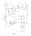
- FIG. 1 shows a refrigeration cycle apparatus 1 according to one embodiment of the present invention.
- the refrigeration cycle apparatus 1 includes: a refrigerant circuit 2 in which a refrigerant circulates; a bypass passage 3; and a controller 4.
- the refrigerant include a zeotropic refrigerant mixture such as R407C, a nearly-azeotropic refrigerant mixture such as R410A, and a single refrigerant.
- the refrigerant circuit 2 includes a compressor 21, a condenser 22, a subcooling heat exchanger 23, a main expansion valve 24 and an evaporator 25 that are connected circularly with pipes.
- a sub accumulator 26 and a main accumulator 27 for performing gas-liquid separation are provided between the evaporator 25 and the compressor 21.
- the refrigerant circuit 2 is also provided with a four-way valve 28 for switching between a normal operation and a defrosting operation.
- the refrigeration cycle apparatus 1 constitutes the heating means of the hot water heater that performs heating by utilizing hot water produced by the heating means
- the condenser 22 is a heat exchanger that heats water by exchanging heat between the refrigerant and the water.
- a supply pipe 71 and a recovery pipe 72 are connected to the condenser 22, so that water is supplied to the condenser 22 through the supply pipe 71 and the water (hot water) heated in the condenser 22 is recovered through the recovery pipe 72.
- the water (hot water) recovered through the recovery pipe 72 is sent to, for example, a heater such as a radiator, directly or through a hot water reservoir tank, and thereby heating is performed.
- the bypass passage 3 is branched from the refrigerant circuit 2 between the subcooling heat exchanger 23 and the main expansion valves 24, and extends through the subcooling heat exchanger 23 to join to the refrigerant circuit 2 between the evaporator 25 and the compressor 21.
- the bypass passage 3 joins to the refrigerant circuit 2 between the sub accumulator 26 and the main accumulator 27.
- a bypass expansion valve 31 is provided in the bypass passage 3 upstream of the subcooling heat exchanger 23.
- the refrigerant discharged from the compressor 21 is sent to the condenser 22 through the four-way valve 28.
- the refrigerant discharged from the compressor 21 is sent to the evaporator 25 through the four-way valve 28.
- FIG. 1 the flowing directions of the refrigerant in the normal operation are indicated by arrows.
- the state change of the refrigerant in the normal operation will be described.
- the high pressure refrigerant discharged from the compressor 21 flows into the condenser 22 and radiates heat to the water passing through the condenser 22.
- the high pressure refrigerant that has flowed out of the condenser 22 flows into the subcooling heat exchanger 23 and is subcooled with the low pressure refrigerant decompressed by the bypass expansion valve 31.
- the high pressure refrigerant that has flowed out of the subcooling heat exchanger 23 is divided to flow separately to the main expansion valve 24 and the bypass expansion valve 31.
- the high pressure refrigerant divided to flow to the main expansion valve 24 is decompressed and expanded by the main expansion valve 24, and then flows into the evaporator 25.
- the low pressure refrigerant that has flowed into the evaporator 25 absorbs heat from the air therein.
- the high pressure refrigerant divided to flow to the bypass expansion valve 31 is decompressed and expanded by the bypass expansion valve 31, and then flows into the subcooling heat exchanger 23.
- the low pressure refrigerant that has flowed into the subcooling heat exchanger 23 is heated with the high pressure refrigerant that has flowed out of the condenser 22.
- the low pressure refrigerant that has flowed out of the subcooling heat exchanger 23 is merged into the low pressure refrigerant that has flowed out of the evaporator 25 and the resulted refrigerant is drawn into the compressor 21 once again.
- the refrigeration cycle apparatus 1 of the present embodiment is configured so as to prevent the situation in which when the outside air temperature is low, the pressure of the refrigerant to be drawn into the compressor 21 is lowered and the circulating amount of the refrigerant is reduced, and thus the heating capacity of the condenser 22 is reduced.
- it is important to increase an enthalpy difference in the evaporator 25 by subcooling the refrigerant, and to suppress the amount of the gaseous phase refrigerant that has a low effect of absorbing heat flowing through a low pressure side of the refrigerant circuit 2 by bypassing the refrigerant with the bypass passage 3, and thereby reducing the pressure loss in the low pressure side of the refrigerant circuit 2.
- the pressure loss in the low pressure side of the refrigerant circuit 2 is reduced, the pressure of the refrigerant to be drawn into the compressor 21 increases by the amount of the reduced pressure loss, reducing the specific volume of the refrigerant. Accordingly, the circulating amount of the refrigerant increases. Moreover, by increasing the enthalpy difference in the evaporator 25, it is possible to ensure the amount of heat absorption in the evaporator 25 even when the mass flow rate of the refrigerant passing through the evaporator 25 lowers due to the bypassing.
- the subcooling heat exchanger 23 is designed to have a heat transfer area that allows a heat exchange ratio Qsc/Qc that is a ratio of an amount of heat exchange Qsc between, in the subcooling heat exchanger 23, the refrigerant that has been decompressed by the bypass expansion means 31 and the refrigerant that has flowed out of the condenser 22 with respect to an amount of heat exchange Qc between, in the condenser 22, the refrigerant that has flowed into the condenser 22 and water is at least 0.2 but not more than 0.8, when openings of the main expansion valve 24 and the bypass expansion valve 31 are adjusted so that a dryness fraction of the refrigerant that has flowed out of the subcooling heat exchanger 23 in the bypass passage 3 is at least 0.8 but less than 1.0.
- the heat transfer area of the subcooling heat exchanger 23 is determined appropriately, it is possible to subcool the refrigerant flowing through the refrigerant circuit 2 into an appropriate state when the dryness fraction of the refrigerant that has flowed out of the subcooling heat exchanger 23 in the bypass passage 3 is maintained at at least 0.8 but less than 1.0, even in the case where the outside air temperature is low and the condenser 22 is required to have a higher heating capacity.
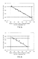
- a dryness fraction Xei of the refrigerant to flow into the evaporator 25 falls in the range of 0 to 0.55 both inclusive when the heat exchange ratio Qsc/Qc is in the range of 0.2 to 0.8 both inclusive under the conditions in which an outside air temperature AT is equal to -25°C and a condensation temperature Tc of the refrigerant in the condenser 22 is equal to 70°C, as shown in FIG. 2 (a) .
- FIG. 2 (a) shows that shows that an outside air temperature AT is equal to -25°C and a condensation temperature Tc of the refrigerant in the condenser 22 is equal to 70°C, as shown in FIG. 2 (a) .
- the refrigerant that has flowed out of the subcooling heat exchanger 23 is in a subcooled state when the dryness fraction Xei of the refrigerant to flow into the evaporator 25 is in the range of 0 to 0.55 both inclusive.
- the refrigerant that has flowed out of the subcooling heat exchanger 23 is in the subcooled state when the heat exchange ratio Qsc/Qc is in the range of 0.2 to 0.8 both inclusive under the conditions in which the outside air temperature AT is equal to -25°C and the condensation temperature Tc of the refrigerant in the condenser 22 is equal to 60°C, as shown in FIG.
- the heat transfer area of the subcooling heat exchanger 23 is determined so that the heat exchange ratio Qsc/Qc is in the range of 0.2 to 0.8 both inclusive.
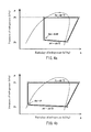
- Pc denotes the pressure of the refrigerant passing through the condenser 22
- Ps denotes the pressure of the refrigerant passing through the evaporator 25.
- the subcooling heat exchanger 23 in the bypass passage 3 has a heat transfer area that allows the heat exchange ratio Qsc/Qc to be at least 0.2 but not more than 0.7 when the dryness fraction of the refrigerant that has flowed out of the subcooling heat exchanger 23 is maintained at at least 0.8 but less than 1.0.
- the dryness fraction Xei in the case where R410A is used as the refrigerant can be maintained at at least 0 but not more than 0.45, and the refrigerant that has flowed out of the subcooling heat exchanger 23 is in the subcooled state (see FIG. 2 (b) , and FIG. 4 (a) and (b) ).
- the bypass passage 3 is provided with an inlet temperature sensor 61 for detecting a temperature (an inflow temperature) Tbi of the refrigerant to flow into the subcooling heat exchanger 23, and an outlet temperature sensor 62 for detecting a temperature (an outflow temperature) Tbo of the refrigerant that has flowed out of the subcooling heat exchanger 23.
- the controller 4 controls the rotation speed of the compressor 21, the switching of the four-way valve 28, and the openings of the main expansion valve 24 and the bypass expansion valve 31, based on the detected values detected by the sensors 61 and 62, etc.
- the controller 4 controls the main expansion valve 24 and the bypass expansion valve 31 so that, in the normal operation, the dryness fraction of the refrigerant that has flowed out of the subcooling heat exchanger 23 in the bypass passage 3 is at least 0.8 but less than 1.0.
- the heat exchange ratio Qsc/Qc is at least 0.2 but not more than 0.8 because the heat transfer area of the subcooling heat exchanger 23 is determined appropriately.
- the method of controlling the heat exchange ratio Qsc/Qc to be at least 0.2 but not more than 0.8 is not limited to the use of the heat transfer area of the subcooling heat exchanger 23.
- the control can be performed by: providing a pressure sensor or a temperature sensor to the condenser 22 to detect the condensation temperature in the condenser 22; providing a temperature sensor at an outlet of the condenser 22; while maintaining the degree of subcooling at the outlet side of the condenser 22, which is the difference between the condensation temperature and the temperature detected by the temperature sensor, at about 1 K to 5 K, controlling the main expansion valve 24 and the bypass expansion valve 31 so that the dryness fraction of the refrigerant that has flowed out of the subcooling heat exchanger 23 is at least 0.8 but less than 1.0.
- the main expansion valve 24 and the bypass expansion valve 31 By controlling the main expansion valve 24 and the bypass expansion valve 31 so that the dryness fraction of the refrigerant that has flowed out of the subcooling heat exchanger 23 in the bypass passage 3 is at least 0.8 but less than 1.0, it is possible to ensure the maximum subcooling effect of the subcooling heat exchanger 23. Thereby, it is possible to increase the difference between the enthalpy of the refrigerant at an inlet of the evaporator 25 and the enthalpy of the refrigerant at an outlet of the evaporator 25.
- controller 4 controls the main expansion valve 24 and the bypass expansion valve 31 so that the inflow temperature Tbi and the outflow temperature Tbo are approximately equal to each other.
- a pressure sensor may be provided at an outlet of the subcooling heat exchanger 23 in the bypass passage 3 or may be provided between the evaporator 25 and the compressors 21 in order to control the main expansion valve 24 and the bypass expansion valve 31 based on the pressure detected by the pressure sensor so that the dryness fraction of the refrigerant that has flowed out of the subcooling heat exchanger 23 in the bypass passage 3 is at least 0.8 but less than 1.0.
- the main expansion valve 24 and the bypass expansion valve 31 may be controlled so that the outflow temperature Tbo conforms to the saturation temperature.
- the evaporating pressure in the evaporator 25 decreases as the outside air temperature AT decreases.
- the degree of subcooling in the subcooling heat exchanger 23 is constant, the dryness fraction of the refrigerant to flow into the evaporator 25 increases, that is, the gaseous refrigerant component that makes no contribution to the evaporation increases. Accordingly, the heat absorbing capacity of the evaporator is lowered.
- the controller 4 controls the main expansion valve 24 and the bypass expansion 31 so that the heat exchange ratio Qsc/Qc increases as the outside air temperature AT decreases.
- the degree of subcooling at the outlet of the subcooling heat exchanger 23 it is possible to increase the degree of subcooling at the outlet of the subcooling heat exchanger 23. Also, by lowering the enthalpy of the refrigerant to flow into the evaporator 25, it is possible to increase the amount of change in the enthalpy of the refrigerant in the evaporator 25, that is, it is possible to increase the heat absorbing capacity of the evaporator 25, compared to the case where the heat exchange ratio Qsc/Qc is low. As a result, when the outside air temperature AT is low, it is possible to complement the decrease in the amount of heat absorbed by the refrigerant in the evaporator 25 caused by the increase in the enthalpy of the refrigerant to flow into the evaporator 25.
- the outside air temperature AT may be detected by an outside air temperature sensor, for example.
- the condensation temperature Tc of the refrigerant increases, it is necessary to increase the degree of subcooling at the outlet of the subcooling heat exchanger 23 when the enthalpy of the refrigerant at the inlet of the evaporator 25 is constant. For that purpose, a rate at which the amount of heat exchange is increased in the subcooling heat exchanger 23 needs to be higher than a rate at which the amount of heat exchange is increased in the condenser 22. In this case, as shown in FIG. 5 , it is preferable to control the main expansion valve 24 and the bypass expansion 31 so that the heat exchange ratio Qsc/Qc increases as the condensation temperature Tc of the refrigerant in the condenser 22 increases.
- the heat exchange ratio Qsc/Qc is low, it is possible to increase the amount of change in the enthalpy of the refrigerant in the evaporator 25, that is, it is possible to increase the heat absorbing capacity of the evaporator 25.
- the outflow temperature Tbo may be used.
- the bypass passage 3 does not necessarily have to be branched from the refrigerant circuit 2 between the subcooling heat exchanger 23 and the main expansion valves 24. It may be branched from the refrigerant circuit 2 between the condenser 22 and the subcooling heat exchangers 23.
- main expansion means and the bypass expansion means of the present invention do not necessarily have to be expansion valves.
- Each of them may be an expander that recovers power from the refrigerant expanding.
- the rotation speed of the expander may be controlled by, for example, changing the load by using a power generator connected to the expander.
- the fluid to be heated in the condenser 22 does not necessarily have to be water, and it may be air. That is, the present invention is applicable also to air conditioners.
- the present invention is particularly useful for hot water heaters that heat water with a refrigeration cycle apparatus and perform heating by utilizing the heated water.
Landscapes
- Engineering & Computer Science (AREA)
- Physics & Mathematics (AREA)
- Mechanical Engineering (AREA)
- Thermal Sciences (AREA)
- General Engineering & Computer Science (AREA)
- Heat-Pump Type And Storage Water Heaters (AREA)
- Compression-Type Refrigeration Machines With Reversible Cycles (AREA)
Applications Claiming Priority (1)
| Application Number | Priority Date | Filing Date | Title |
|---|---|---|---|
| JP2009231660A JP5411643B2 (ja) | 2009-10-05 | 2009-10-05 | 冷凍サイクル装置および温水暖房装置 |
Publications (2)
| Publication Number | Publication Date |
|---|---|
| EP2320164A2 true EP2320164A2 (fr) | 2011-05-11 |
| EP2320164A3 EP2320164A3 (fr) | 2014-02-05 |
Family
ID=43778548
Family Applications (1)
| Application Number | Title | Priority Date | Filing Date |
|---|---|---|---|
| EP10186449.4A Withdrawn EP2320164A3 (fr) | 2009-10-05 | 2010-10-04 | Appareil de cycle de réfrigération et radiateur à eau chaude |
Country Status (3)
| Country | Link |
|---|---|
| EP (1) | EP2320164A3 (fr) |
| JP (1) | JP5411643B2 (fr) |
| CN (1) | CN102032699B (fr) |
Cited By (4)
| Publication number | Priority date | Publication date | Assignee | Title |
|---|---|---|---|---|
| GB2495149A (en) * | 2011-09-30 | 2013-04-03 | Arctic Circle Ltd | Refrigeration Apparatus With Subcooler |
| EP2733437A1 (fr) * | 2012-11-20 | 2014-05-21 | Panasonic Corporation | Chauffe-eau à pompe de chaleur |
| WO2017099814A1 (fr) * | 2015-12-08 | 2017-06-15 | Trane International Inc. | Utilisation de la chaleur récupérée d'une source de chaleur pour obtenir de l'eau chaude à haute température |
| US12215905B2 (en) | 2019-03-26 | 2025-02-04 | Fujitsu General Limited | Air conditioning apparatus |
Families Citing this family (10)
| Publication number | Priority date | Publication date | Assignee | Title |
|---|---|---|---|---|
| EP2765370A1 (fr) * | 2013-02-08 | 2014-08-13 | Panasonic Corporation | Appareil à cycle de réfrigération et le générateur d'eau chaude associé |
| JP6131741B2 (ja) * | 2013-07-03 | 2017-05-24 | 富士電機株式会社 | 冷媒回路装置 |
| CN103344066A (zh) * | 2013-07-15 | 2013-10-09 | 江苏七政新能源有限公司 | 一种弯管式冷却器 |
| EP3118542B1 (fr) | 2014-03-14 | 2021-05-19 | Mitsubishi Electric Corporation | Dispositif à cycle de réfrigération |
| EP3023711A1 (fr) * | 2014-11-20 | 2016-05-25 | Vaillant GmbH | Contrôle de l'énergie d'injection de vapeur |
| CN106225273A (zh) * | 2016-07-29 | 2016-12-14 | 青岛海尔特种电冰柜有限公司 | 制冷循环系统及制冷设备 |
| PL3677855T3 (pl) * | 2018-06-07 | 2024-03-18 | Panasonic Intellectual Property Management Co., Ltd. | Urządzenie obiegu chłodniczego oraz zawierające je urządzenie do podgrzewania cieczy |
| CN112771319A (zh) * | 2018-09-25 | 2021-05-07 | 东芝开利株式会社 | 制冷循环装置 |
| WO2021048905A1 (fr) * | 2019-09-09 | 2021-03-18 | 三菱電機株式会社 | Unité extérieure et dispositif à cycle frigorifique |
| US20220128283A1 (en) * | 2020-10-23 | 2022-04-28 | General Electric Company | Vapor cycle system for cooling components and associated method |
Citations (1)
| Publication number | Priority date | Publication date | Assignee | Title |
|---|---|---|---|---|
| JPH0436288B2 (fr) | 1984-07-16 | 1992-06-15 | Tooru Seki |
Family Cites Families (10)
| Publication number | Priority date | Publication date | Assignee | Title |
|---|---|---|---|---|
| JPH0544675Y2 (fr) * | 1988-05-19 | 1993-11-12 | ||
| JPH0814676A (ja) * | 1994-06-28 | 1996-01-19 | Daikin Ind Ltd | 空気調和機 |
| CN1205073A (zh) * | 1996-08-14 | 1999-01-13 | 大金工业株式会社 | 空调机 |
| EP1033541B1 (fr) * | 1997-11-17 | 2004-07-21 | Daikin Industries, Limited | Appareil refrigerant |
| JP4356146B2 (ja) * | 1999-07-21 | 2009-11-04 | ダイキン工業株式会社 | 冷凍装置 |
| CN1149366C (zh) * | 1999-10-18 | 2004-05-12 | 大金工业株式会社 | 冷冻设备 |
| JP4036288B2 (ja) * | 2002-07-11 | 2008-01-23 | 株式会社日立製作所 | 空気調和装置 |
| JP4269323B2 (ja) * | 2004-03-29 | 2009-05-27 | 三菱電機株式会社 | ヒートポンプ給湯機 |
| JP4771721B2 (ja) * | 2005-03-16 | 2011-09-14 | 三菱電機株式会社 | 空気調和装置 |
| JP2007212134A (ja) * | 2007-04-11 | 2007-08-23 | Daikin Ind Ltd | 空気調和装置 |
-
2009
- 2009-10-05 JP JP2009231660A patent/JP5411643B2/ja not_active Expired - Fee Related
-
2010
- 2010-09-30 CN CN201010539415.8A patent/CN102032699B/zh not_active Expired - Fee Related
- 2010-10-04 EP EP10186449.4A patent/EP2320164A3/fr not_active Withdrawn
Patent Citations (1)
| Publication number | Priority date | Publication date | Assignee | Title |
|---|---|---|---|---|
| JPH0436288B2 (fr) | 1984-07-16 | 1992-06-15 | Tooru Seki |
Cited By (5)
| Publication number | Priority date | Publication date | Assignee | Title |
|---|---|---|---|---|
| GB2495149A (en) * | 2011-09-30 | 2013-04-03 | Arctic Circle Ltd | Refrigeration Apparatus With Subcooler |
| EP2733437A1 (fr) * | 2012-11-20 | 2014-05-21 | Panasonic Corporation | Chauffe-eau à pompe de chaleur |
| WO2017099814A1 (fr) * | 2015-12-08 | 2017-06-15 | Trane International Inc. | Utilisation de la chaleur récupérée d'une source de chaleur pour obtenir de l'eau chaude à haute température |
| US11231205B2 (en) | 2015-12-08 | 2022-01-25 | Trane International Inc. | Using heat recovered from heat source to obtain high temperature hot water |
| US12215905B2 (en) | 2019-03-26 | 2025-02-04 | Fujitsu General Limited | Air conditioning apparatus |
Also Published As
| Publication number | Publication date |
|---|---|
| CN102032699B (zh) | 2014-10-22 |
| CN102032699A (zh) | 2011-04-27 |
| JP5411643B2 (ja) | 2014-02-12 |
| EP2320164A3 (fr) | 2014-02-05 |
| JP2011080634A (ja) | 2011-04-21 |
Similar Documents
| Publication | Publication Date | Title |
|---|---|---|
| EP2320164A2 (fr) | Appareil de cycle de réfrigération et radiateur à eau chaude | |
| JP5533491B2 (ja) | 冷凍サイクル装置及び温水暖房装置 | |
| JP6161005B2 (ja) | 冷凍サイクル装置およびそれを備えた温水生成装置 | |
| JP5042262B2 (ja) | 空調給湯複合システム | |
| EP2320165A2 (fr) | Appareil de cycle de réfrigération et radiateur à eau chaude | |
| EP2131122A1 (fr) | Dispositif de pompe à chaleur | |
| EP2902726B1 (fr) | Système pour alimentation en eau chaude et pour conditionnement d'air combinés | |
| JP5278451B2 (ja) | 冷凍サイクル装置及びそれを用いた温水暖房装置 | |
| JP6223469B2 (ja) | 空気調和装置 | |
| JP5518102B2 (ja) | 空調給湯複合システム | |
| JP5300806B2 (ja) | ヒートポンプ装置 | |
| WO2015125743A1 (fr) | Dispositif de climatisation | |
| JP2013002744A (ja) | 冷凍サイクル装置及びそれを備えた温水暖房装置 | |
| JP2011174672A (ja) | 冷凍サイクル装置および温水暖房装置 | |
| JP2017155944A (ja) | 冷凍サイクル装置及びそれを備えた温水暖房装置 | |
| JPWO2010082324A1 (ja) | 空調給湯複合システム | |
| JP2011185507A (ja) | 冷凍サイクル装置およびそれを備えた温水暖房装置 | |
| JP5233960B2 (ja) | 冷凍サイクル装置及びそれを用いた温水暖房装置 |
Legal Events
| Date | Code | Title | Description |
|---|---|---|---|
| PUAI | Public reference made under article 153(3) epc to a published international application that has entered the european phase |
Free format text: ORIGINAL CODE: 0009012 |
|
| AK | Designated contracting states |
Kind code of ref document: A2 Designated state(s): AL AT BE BG CH CY CZ DE DK EE ES FI FR GB GR HR HU IE IS IT LI LT LU LV MC MK MT NL NO PL PT RO RS SE SI SK SM TR |
|
| AX | Request for extension of the european patent |
Extension state: BA ME |
|
| RIN1 | Information on inventor provided before grant (corrected) |
Inventor name: ISAYAMA, YASUHIKO Inventor name: OKAZA, NORIHO Inventor name: MORIWAKI, SHUNJI Inventor name: AOYAMA, SHIGEO |
|
| PUAL | Search report despatched |
Free format text: ORIGINAL CODE: 0009013 |
|
| RIC1 | Information provided on ipc code assigned before grant |
Ipc: F25B 40/02 20060101AFI20131218BHEP |
|
| RIC1 | Information provided on ipc code assigned before grant |
Ipc: F25B 40/02 20060101AFI20131220BHEP |
|
| AK | Designated contracting states |
Kind code of ref document: A3 Designated state(s): AL AT BE BG CH CY CZ DE DK EE ES FI FR GB GR HR HU IE IS IT LI LT LU LV MC MK MT NL NO PL PT RO RS SE SI SK SM TR |
|
| AX | Request for extension of the european patent |
Extension state: BA ME |
|
| STAA | Information on the status of an ep patent application or granted ep patent |
Free format text: STATUS: THE APPLICATION IS DEEMED TO BE WITHDRAWN |
|
| 18D | Application deemed to be withdrawn |
Effective date: 20140806 |