EP2320203A1 - Dispositif et procédé de mesure de vibrations - Google Patents
Dispositif et procédé de mesure de vibrations Download PDFInfo
- Publication number
- EP2320203A1 EP2320203A1 EP10189231A EP10189231A EP2320203A1 EP 2320203 A1 EP2320203 A1 EP 2320203A1 EP 10189231 A EP10189231 A EP 10189231A EP 10189231 A EP10189231 A EP 10189231A EP 2320203 A1 EP2320203 A1 EP 2320203A1
- Authority
- EP
- European Patent Office
- Prior art keywords
- sensor
- vibration
- alignment
- characteristic
- machine
- Prior art date
- Legal status (The legal status is an assumption and is not a legal conclusion. Google has not performed a legal analysis and makes no representation as to the accuracy of the status listed.)
- Granted
Links
Images


Classifications
-
- G—PHYSICS
- G01—MEASURING; TESTING
- G01H—MEASUREMENT OF MECHANICAL VIBRATIONS OR ULTRASONIC, SONIC OR INFRASONIC WAVES
- G01H1/00—Measuring characteristics of vibrations in solids by using direct conduction to the detector
- G01H1/003—Measuring characteristics of vibrations in solids by using direct conduction to the detector of rotating machines
-
- G—PHYSICS
- G01—MEASURING; TESTING
- G01B—MEASURING LENGTH, THICKNESS OR SIMILAR LINEAR DIMENSIONS; MEASURING ANGLES; MEASURING AREAS; MEASURING IRREGULARITIES OF SURFACES OR CONTOURS
- G01B11/00—Measuring arrangements characterised by the use of optical techniques
- G01B11/26—Measuring arrangements characterised by the use of optical techniques for measuring angles or tapers; for testing the alignment of axes
- G01B11/27—Measuring arrangements characterised by the use of optical techniques for measuring angles or tapers; for testing the alignment of axes for testing the alignment of axes
- G01B11/272—Measuring arrangements characterised by the use of optical techniques for measuring angles or tapers; for testing the alignment of axes for testing the alignment of axes using photoelectric detection means
-
- G—PHYSICS
- G01—MEASURING; TESTING
- G01M—TESTING STATIC OR DYNAMIC BALANCE OF MACHINES OR STRUCTURES; TESTING OF STRUCTURES OR APPARATUS, NOT OTHERWISE PROVIDED FOR
- G01M13/00—Testing of machine parts
- G01M13/02—Gearings; Transmission mechanisms
- G01M13/028—Acoustic or vibration analysis
Definitions
- the invention relates to a device and a method for measurement of vibrations at a non-rotating part of a rotating machine
- Devices are known with which alignment for example of two shafts to one another can be measured.
- motors for example drive pumps, the relative alignment from the motor to generally heavier pumps having a major effect on the service life of the entire machine and its components.
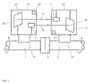
- These devices contain an electronic evaluation device, a first optoelectronic transmitting and/or receiving unit and a second optoelectronic transmitting and/or receiving unit or a reflector instead of the second transmitting and/or receiving unit.
- These devices are described for example in EP 0 145 745 or EP 0 367 814 .
- an optoelectronic transmitting and/or receiving unit hereinafter also called an alignment sensor
- an alignment sensor of an alignment device
- the vibration sensor and the sensor of the alignment device had always been connected separately to the electronic evaluation device.
- These combined devices for alignment and for vibration measurement are available for example from the applicant under the name smartSCANNER.
- Both alignment sensors like the first optoelectronic transmitting and/or receiving unit and a second optoelectronic transmitting and/or receiving unit (which can also be omitted when using a reflector) as well as vibration sensors can be connected to the electronic evaluation unit of the smartSCANNER.
- An inclinometer is contained in at least one of the two optoelectronic transmitting and/or receiving units.
- Ii is an object of the invention to provide for a machine vibration measurement device which can be handled in a particularly simple manner, while being of relatively low complexity. It is also an object to provide for a corresponding vibration measurement method.
- the invention is beneficial in that, by providing the device with an accelerometer/inclinometer sensor for measuring acceleration forces resulting from the machine vibrations and for also measuring gravity and by determining the orientation of the sensor with regard to gravity from the stationary component of the sensor output and evaluating the non-stationary components of sensor output at according to the determined sensor orientation, the measurement procedure is simplified, since the device, due to the integrated inclinometer function, is able to determine the orientation of the sensor with regard to gravity in the measurement position and to automatically interprete/evaluate the acceleration measurement data accordingly, without the need for an additional inclinometer to be added to the accelerometer sensor.
- the device comprises a first optoelectronic transmitting and/or receiving unit in a first housing, a second optoelectronic transmitting and/or receiving unit with a housing or a reflector in a second housing, and at least one of the optoelectronic transmitting and/or receiving units being connected to the electronic evaluation unit, and wherein the sensor is connected to one of the optoelectronic transmitting and/or receiving units.
- data determined from the sensor output is used to determine a characteristic for the quality of alignment of the machine.
- Simplification of the measurement process can be achieved in that the measurement device displays a characteristic for the combination of the alignment quality and the vibration picture and it is further communicated to the user on the display of the measurement device how many of the data necessary for determining of the characteristics have been recorded. This characteristic is displayed to the personnel in an easily accessible and understandable form. Thus, prompt and simple joint evaluation of the result of the alignment process and of the vibration picture becomes possible.
- Simplification of handling may be achieved by the vibration sensor (i.e. the accelerometer/inclinometer sensor) being connected not to the electronic evaluation unit, as in the past, but directly to the alignment sensor, or its preferably being installed in the alignment sensor. This results in that the operators are forced to handle the alignment sensor in the preparation of the vibration measurements after completed alignment. Thus the alignment sensor cannot be forgotten on the machine.
- This embodiment may be further improved by the second measure of display of the degree of detection of a common characteristic for the alignment as claimed in the invention and for the vibration picture and display of this characteristic.
- the accelerometer/inclinometer sensor contained in at least one of the two optoelectronic transmitting and/or receiving units also enables checking of the alignment of the accelerometer/inclinometer sensor in the vibration measurement, especially whether alignment of the accelerometer/inclinometer sensor is in the axial direction to the aligned shafts or in the radial direction to them. In this way the reliability of the determined vibration data is greatly increased.
- the accelerometer/inclinometer sensor is made as a MEMS module.
- the accelerometer/inclinometer has two or three measurement axes, thereby enabling a two- or three-dimensional inclinometer function and two- or three-axes vibration measurements.
- Another option for simplification of operation and handling of this combined vibration and alignment device is the display of an easily understandable value in the form of a characteristic with which a prompt and reliable conclusion about the instantaneous vibration state and the success of the alignment measure is made available to the operators.
- This factor also encompasses the fact that the personnel of a combined alignment and vibration measurement device on the display of the electronic evaluation device are also notified of how many of the data required for determining this characteristic have been recorded with the device.
- the common characteristic for alignment and the vibration picture takes into account the values measured after alignment with the alignment sensor and the alignment tolerances as well as the vibration picture after restarting the machine.
- different vibration characteristics can be used. These vibration characteristics can be the following: the ratio of the vibration intensity measured in the radial direction to the vibration intensity measured in the axial direction, the ratio of the vibration signal measured at the current rotary frequency of the machine to the vibration signal measured at the harmonic of the current rotary frequency, the ratio of the vibration signal in operation of the machine before alignment to the vibration signal recorded under comparable conditions in the operation of the machine after alignment.
- the MEMS inclinometer 19 is mounted in the vicinity of one corner of the housing 15. So that it is possible to place the housing of the transmitting and receiving unit on a machine to be measured, this corner is provided with one or more guide edges, guide surfaces or guide bezels and is shaped to the inside, as indicated in Figure 2 .
- the guide edges or guide bezels need not necessarily be straight, as in the figure. There can also be angles other than 90° between the guide edges or guide bezels. If for example there are three guide surfaces, one corner of the housing is turned up so to speak to the inside and acquires the shape of a triple mirror. So that the guide surfaces, edges or bezels enable good coupling to the machine to be measured for vibration measurement, they are preferably convexly curved.
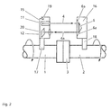
- FIG. 3 shows another embodiment of the invention.
- a housing 15 which is attached to the shaft 1 with a holding device 17 contains a light source 11 which emits a light beam 4.
- This light beam is received in a first detector 9 mounted on the shaft 2 with a holding device 18 in a housing 16, and a second detector 10.
- These detectors are mounted in succession in the beam path. If the detector 9 which is located nearer the entry opening in the beam path is not transparent enough, the attachment of the two detectors at different distances to the light source 11 can be accomplished for example by means of a beam splitter.
- the housing 15 again contains an inclinometer 19. In one recess of the housing 16 a accelerometer/inclinometer vibration sensor 21 or a probe tip is inserted in order to take the vibration measurement.
- the optoelectronic receiving unit in the housing 16 is attached with two rods to a clamping device 18 on the shaft to be aligned which has a prism-shaped depression for adaptation to the shaft.
- the two rods extend parallel to one another from this clamping device and parallel to a line which runs radially to the shaft.
- the housing 16 has two openings which penetrate the housing to hold the rods.
- the housing 16 and the optoelectronic receiving device contained in it are then fixed at a certain distance to the shaft, for example by way of clamping screws. These openings can be feasibly used for inserting a vibration sensor by for example their inner sides being provided with electrical contacts.
- the vibration sensor 21 to be inserted When the corresponding contacts on the vibration sensor 21 to be inserted are pressed to the outside with springs, reliable electrical contact-making is achieved.
- the vibration sensor is made as a two-axle or three-axle vibration sensor.
- the vibration sensor is integrated into the housing and permanently installed. A probe tip is inserted into an opening provided for this purpose in the vicinity of this integrated vibration sensor. This probe tip is suitable only for recording vibration signals in one dimension.
- All alignment devices of Figures 1 to 3 also contain an electronic evaluation unit which was not shown here.
- the transmitting and/or receiving units are connected by means of cables or wirelessly to this evaluation unit.
- This electronic evaluation unit is used for communication with the operators. How many of the data to be recorded have already been determined is communicated to the user on the display of this evaluation unit.
- working with this device begins with determination of the alignment when the system is shut down. Afterwards this alignment is corrected. The success of this correction is displayed on the display of the evaluation unit in the form of a comparison between the alignment tolerances and the determined offset values.
- FIG. 4 shows a table with allowable tolerance values dependent on the shaft rpm.
- the alignment characteristic can be for example in the region of 100. Maintaining the tolerance values labeled "Acceptable” in Figure 4 can for example cause an alignment characteristic in the vicinity of 50. Values for the offset which are outside of this tolerance lead to an evaluation of the alignment with a characteristic near zero.
- This indication can take place for example in the form of a bar and/or a percentage. This indication is designed to signal to the personnel that a vibration measurement must still be taken when the system has been started again. If after completion of the alignment process on the display of the electronic evaluation unit it is signalled that only part of the measurement task has been completed, this is a reason for the operators to remove the optoelectronic transmitting and/or receiving units from the shafts of the machine. In this way the process becomes safer. Damage to the measurement device can thus be avoided since the alignment sensors cannot be inadvertently forgotten on the shafts. The personnel thereupon prepare the alignment sensor for a vibration sensor or a probe tip to be connected to the alignment sensor when the vibration sensor is not integrated in the alignment sensor anyway.
- a vibration measurement can be taken with the alignment sensor and the vibration sensor.
- This vibration measurement best takes place once in the radial direction with reference to the two shafts which are aligned to one another and a second time in the axial direction with reference to the shafts which are aligned to one another.
- this measurement can be taken with a single vibration sensor which is sensitive to vibrations in two or three spatial axes.
- a vibration characteristic can now be computed from the result of this vibration measurement or several measurements. This vibration characteristic can contain the ratio of the axial vibration to the radial vibration.
- this vibration measurement can likewise be used for formation of the vibration characteristic.
- One example is the ratio of the vibration intensity in operation before alignment to the vibration intensity in operation after alignment.
- measurements in the radial and axial direction after alignment can also be used and are combined with measurements in the radial and axial direction before alignment in order to obtain a vibration characteristic.
- the evaluation unit is for determining the orientation of the sensor with regard to gravity from the stationary component of the sensor output and for evaluating the non-stationary components of the sensor output, i.e. the vibration signals, according to the determined sensor orientation.
- the evaluation unit is adapted to transform the acceleration values measured along the measurement axes into acceleration values along the vertical axis and along two orthogonal horizontal axes.
- the degree of execution of the tasks to be performed with the measurement device is set such that at this point all activities are considered completed.
- a graphic representation on the display of the electronic evaluation unit as a bar is complete, a percentage displayed there is now 100.
- the alignment characteristic in the memory of the electronic evaluation unit two characteristics are now stored, specifically on the one hand the alignment characteristic and on the other hand the vibration characteristic.
- These two characteristics can be normalized in a suitable manner.
- An alignment characteristic of 100 can for example constitute perfect alignment, an alignment characteristic near zero can mean very poor alignment.
- the vibration characteristic can be similarly normalized so that a vibration characteristic of 100 constitutes a good vibration picture, while a vibration characteristic near zero represents a poor vibration picture.
- the ratio of the alignment characteristic to the vibration characteristic or the inverse thereof is displayed as a fraction on the display of the electronic evaluation direction. With this display as a fraction, it is also possible by computation to combine these two characteristics into one.
- numerators and denominators of the fraction indicate how successful the process of alignment was or how good the vibration picture present after alignment is.
- a display of the two values of the numerator and denominator of the fraction further facilitates handling of the device for the operators.
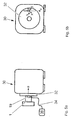
- Figs. 5a and 5b an example of a vibration measurement device according to the invention is shown which is not used in combination an alignment device.
- an accelerometer/inclinometer vibration sensor 19 is positioned at a non-rotating part 32, e.g. a bearing cover, of a machine 30 comprising a rotating part, such as a shaft 1, for conducting vibration measurements during operation of the machine 30.
- the sensor 19 is fixed at the machine part 32 via a magnetic holder.
- the sensor 19 is connected via a cable 34 to an electronic evaluation unit 36.
- the evaluation unit determines the orientation of the sensor 19 with regard to gravity from the stationary component of the sensor output and evaluates the non-stationary components of the sensor output, i.e. the vibration signals, according to the determined sensor orientation.
- the evaluation unit transforms the acceleration values measured along the measurement axes x, y, z of the sensor 19 into acceleration values along the vertical axis v, a horizontal axis h and an axial axis a of the machine (the axial axis a is also horizontal but orthogonal to horizontal axis labelled h).
- the measurement device as such cannot distinguish between horizontal directions h and a based on the inclinometer signal; rather, by the positioning the sensor 19 at a surface parallel or perpendicular to the axis a of the rotating part 1, one of the horizontal directions, namely the axial axis a, is defined; the other horizontal direction then is assumed to be the axis h.
- the measurement device supports the user by automatically recognizing the vertical axis v based on the inclinometer signal provided by the sensor 19, so that the user dioes not have to care about the positioning of the sensor 19 with regard to vertical. Thereby, at least as far as the vertical axis is concerned, the measurement device is able to automatically recognize different measurement positions at the machine.
Landscapes
- Physics & Mathematics (AREA)
- General Physics & Mathematics (AREA)
- Acoustics & Sound (AREA)
- Measurement Of Mechanical Vibrations Or Ultrasonic Waves (AREA)
- Investigating Materials By The Use Of Optical Means Adapted For Particular Applications (AREA)
Applications Claiming Priority (1)
| Application Number | Priority Date | Filing Date | Title |
|---|---|---|---|
| DE102009053132A DE102009053132A1 (de) | 2009-11-05 | 2009-11-05 | Vorrichtung zur Messung der relativen Ausrichtung zweier Gegenstände und zur Schwingungsmessung und Verfahren zur Bestimmung einer Qualitätskennzahl |
Publications (2)
| Publication Number | Publication Date |
|---|---|
| EP2320203A1 true EP2320203A1 (fr) | 2011-05-11 |
| EP2320203B1 EP2320203B1 (fr) | 2012-12-12 |
Family
ID=43618351
Family Applications (2)
| Application Number | Title | Priority Date | Filing Date |
|---|---|---|---|
| EP20100189231 Active EP2320203B1 (fr) | 2009-11-05 | 2010-10-28 | Dispositif et procédé de mesure de vibrations |
| EP20100189232 Not-in-force EP2320204B1 (fr) | 2009-11-05 | 2010-10-28 | Dispositif et procédé de mesure de l'alignement et de la vibration d'une machine rotative |
Family Applications After (1)
| Application Number | Title | Priority Date | Filing Date |
|---|---|---|---|
| EP20100189232 Not-in-force EP2320204B1 (fr) | 2009-11-05 | 2010-10-28 | Dispositif et procédé de mesure de l'alignement et de la vibration d'une machine rotative |
Country Status (2)
| Country | Link |
|---|---|
| EP (2) | EP2320203B1 (fr) |
| DE (1) | DE102009053132A1 (fr) |
Cited By (3)
| Publication number | Priority date | Publication date | Assignee | Title |
|---|---|---|---|---|
| EP2559979A2 (fr) | 2011-08-16 | 2013-02-20 | Prüftechnik Dieter Busch AG | Dispositif et procédé pour détecter les vibrations de machine |
| US8607635B2 (en) | 2009-11-05 | 2013-12-17 | Pruftechnik Dieter Busch Ag | Device for measuring the relative alignment of two articles, method for determining a quality characteristic and vibration measurement device and method |
| WO2023094675A1 (fr) * | 2021-11-29 | 2023-06-01 | Sandvik Mining and Construction Deutschland GmbH | Procédé de mesure de vibrations d'une machine à vibrations |
Families Citing this family (4)
| Publication number | Priority date | Publication date | Assignee | Title |
|---|---|---|---|---|
| DE102012103980A1 (de) | 2012-05-07 | 2013-11-07 | GOM - Gesellschaft für Optische Meßtechnik mbH | Verfahren und Vorrichtung zur Ausrichtung einer Komponente |
| DE102015205710A1 (de) * | 2015-03-30 | 2016-10-06 | Prüftechnik Dieter Busch AG | Verfahren zum Anordnen eines Laserausrichtsystems an einer Vorrichtung mit zwei durch eine Kupplung miteinander verbundenen Wellen und Laserausrichtsystem mit einer ersten Einrichtung und einer zweiten Einrichtung |
| CN105954029B (zh) * | 2016-06-24 | 2019-01-25 | 湖南科技大学 | 风电机组传动链轴系动态不对中振动模拟系统及模拟方法 |
| CN111829492B (zh) * | 2020-07-24 | 2021-11-30 | 中交第二航务工程局有限公司 | 基于激光垂准仪应用的联系测量方法 |
Citations (6)
| Publication number | Priority date | Publication date | Assignee | Title |
|---|---|---|---|---|
| EP0145745A1 (fr) | 1983-06-03 | 1985-06-26 | Busch Dieter & Co Prueftech | Installation pour determiner des erreurs d'alignement pour des arbres disposes les uns derriere les autres. |
| EP0367814A1 (fr) | 1988-04-28 | 1990-05-16 | Busch Dieter & Co Prueftech | Dispositif pour determiner la position relative de l'axe de reference d'un objet par rapport a un rayon de reference, en particulier un rayon laser. |
| US4984173A (en) * | 1989-06-09 | 1991-01-08 | General Electric Company | System for aligning a rotating line-shaft |
| EP0999433A2 (fr) | 1998-11-06 | 2000-05-10 | Prüftechnik Dieter Busch Ag | Dispositif et procédé d'acquistion des signaux des vibrations et/ou de son structurel |
| US20050018537A1 (en) * | 2003-07-21 | 2005-01-27 | Welker Kenneth E. | Cable motion detection |
| DE102006015461A1 (de) * | 2005-04-20 | 2006-11-02 | Prüftechnik Dieter Busch AG | Vorrichtung für die Messung von Kurbelwellen-Kennwerten |
Family Cites Families (7)
| Publication number | Priority date | Publication date | Assignee | Title |
|---|---|---|---|---|
| EP2264397B1 (fr) * | 1999-12-08 | 2015-10-07 | PRÜFTECHNIK Dieter Busch AG | Sonde de mesure d'orientation pour aligner de éléments entre eux et procédé utilisée à cet effet |
| US6873931B1 (en) * | 2000-10-10 | 2005-03-29 | Csi Technology, Inc. | Accelerometer based angular position sensor |
| SE527161C2 (sv) * | 2004-03-08 | 2006-01-10 | Spm Instr Ab | Mätdon, anordning och system samt metod för objektuppriktning |
| DE502006004670D1 (de) * | 2005-04-20 | 2009-10-08 | Busch Dieter & Co Prueftech | Enatmung an kurbelwellen |
| US7460977B2 (en) * | 2007-02-19 | 2008-12-02 | Fixturlaser Ab | Method and apparatus for alignment of components |
| DE102008023109A1 (de) * | 2007-09-14 | 2009-03-19 | Prüftechnik Dieter Busch AG | Windenergieanlage und Verfahren zum Betreiben einer Windenergieanlage |
| DE202007015532U1 (de) * | 2007-11-08 | 2009-03-26 | Hartmann Codier Gmbh | Neigungssensor |
-
2009
- 2009-11-05 DE DE102009053132A patent/DE102009053132A1/de not_active Withdrawn
-
2010
- 2010-10-28 EP EP20100189231 patent/EP2320203B1/fr active Active
- 2010-10-28 EP EP20100189232 patent/EP2320204B1/fr not_active Not-in-force
Patent Citations (6)
| Publication number | Priority date | Publication date | Assignee | Title |
|---|---|---|---|---|
| EP0145745A1 (fr) | 1983-06-03 | 1985-06-26 | Busch Dieter & Co Prueftech | Installation pour determiner des erreurs d'alignement pour des arbres disposes les uns derriere les autres. |
| EP0367814A1 (fr) | 1988-04-28 | 1990-05-16 | Busch Dieter & Co Prueftech | Dispositif pour determiner la position relative de l'axe de reference d'un objet par rapport a un rayon de reference, en particulier un rayon laser. |
| US4984173A (en) * | 1989-06-09 | 1991-01-08 | General Electric Company | System for aligning a rotating line-shaft |
| EP0999433A2 (fr) | 1998-11-06 | 2000-05-10 | Prüftechnik Dieter Busch Ag | Dispositif et procédé d'acquistion des signaux des vibrations et/ou de son structurel |
| US20050018537A1 (en) * | 2003-07-21 | 2005-01-27 | Welker Kenneth E. | Cable motion detection |
| DE102006015461A1 (de) * | 2005-04-20 | 2006-11-02 | Prüftechnik Dieter Busch AG | Vorrichtung für die Messung von Kurbelwellen-Kennwerten |
Cited By (8)
| Publication number | Priority date | Publication date | Assignee | Title |
|---|---|---|---|---|
| US8607635B2 (en) | 2009-11-05 | 2013-12-17 | Pruftechnik Dieter Busch Ag | Device for measuring the relative alignment of two articles, method for determining a quality characteristic and vibration measurement device and method |
| US9400209B2 (en) | 2009-11-05 | 2016-07-26 | Prüftechnik Dieter Busch AG | Device for measuring the relative alignment of two articles, and vibration measurement device |
| US9482574B2 (en) | 2009-11-05 | 2016-11-01 | Prueftechnik Dieter Busch Ag | Method for determining a quality characteristic and for vibration measurement |
| US9605997B2 (en) | 2009-11-05 | 2017-03-28 | Prueftechnik Dieter Busch Ag | Method for determining a quality characteristic and vibration measurement method |
| EP2559979A2 (fr) | 2011-08-16 | 2013-02-20 | Prüftechnik Dieter Busch AG | Dispositif et procédé pour détecter les vibrations de machine |
| DE102012014277A1 (de) | 2011-08-16 | 2013-02-21 | Prüftechnik Dieter Busch AG | Vorrichtung und Verfahren zum Erfassen von Maschinenschwingungen |
| WO2023094675A1 (fr) * | 2021-11-29 | 2023-06-01 | Sandvik Mining and Construction Deutschland GmbH | Procédé de mesure de vibrations d'une machine à vibrations |
| US20250027836A1 (en) * | 2021-11-29 | 2025-01-23 | Sandvik Rock Processing Australia Pty Limited | Method for measuring vibrations of a vibration machine |
Also Published As
| Publication number | Publication date |
|---|---|
| EP2320203B1 (fr) | 2012-12-12 |
| EP2320204A3 (fr) | 2011-06-15 |
| EP2320204A2 (fr) | 2011-05-11 |
| DE102009053132A1 (de) | 2011-05-12 |
| EP2320204B1 (fr) | 2014-01-01 |
Similar Documents
| Publication | Publication Date | Title |
|---|---|---|
| US9605997B2 (en) | Method for determining a quality characteristic and vibration measurement method | |
| EP2320203B1 (fr) | Dispositif et procédé de mesure de vibrations | |
| US9921136B2 (en) | Wireless collection and analysis of machine data | |
| US5544073A (en) | Rotor balancing calculator | |
| US10533920B2 (en) | Automatic rotating-machine fault diagnosis with confidence level indication | |
| EP2559979A2 (fr) | Dispositif et procédé pour détecter les vibrations de machine | |
| US9009000B2 (en) | Method for evaluating mounting stability of articulated arm coordinate measurement machine using inclinometers | |
| JP6918738B2 (ja) | センサシステム | |
| JP2000517047A (ja) | 状態分析器 | |
| US20130042682A1 (en) | Device and method for detecting machine vibrations | |
| CN108473287A (zh) | 提升架 | |
| EP3929460B1 (fr) | Système de détection d'anomalies et procédé de détection d'anomalies | |
| CN110579198B (zh) | 一种监测涡轮叶尖间隙的装置及方法 | |
| US20220161297A1 (en) | Operation monitoring system for sifting device | |
| US20190128724A1 (en) | Determining a fill level of a hydrodynamic clutch | |
| CN106092142A (zh) | 一种惯导标定系统计量检定装置 | |
| CN208580215U (zh) | 一种双摄像头多方位移动检测装置 | |
| GB2550541A (en) | Monitoring device | |
| CN110455313A (zh) | 一种光纤陀螺的检测装置 | |
| EP3795946B1 (fr) | Appareil d'arpentage tridimensionnel, procédé d'arpentage tridimensionnel et programme d'arpentage tridimensionnel | |
| CN108955583A (zh) | 一种隧道掌子面横截面积测量仪及测量方法 | |
| CN110792427A (zh) | 抽油机检测装置、抽油机报警装置和抽油机报警系统 | |
| US8532956B2 (en) | Method and system for rotation tracking of a turbomachine component | |
| KR20110125956A (ko) | 휴대형 진동 측정 장치 및 이를 이용한 진동 분석 시스템 | |
| CN212007212U (zh) | 智能多用途激光测量仪 |
Legal Events
| Date | Code | Title | Description |
|---|---|---|---|
| PUAI | Public reference made under article 153(3) epc to a published international application that has entered the european phase |
Free format text: ORIGINAL CODE: 0009012 |
|
| AK | Designated contracting states |
Kind code of ref document: A1 Designated state(s): AL AT BE BG CH CY CZ DE DK EE ES FI FR GB GR HR HU IE IS IT LI LT LU LV MC MK MT NL NO PL PT RO RS SE SI SK SM TR |
|
| AX | Request for extension of the european patent |
Extension state: BA ME |
|
| 17P | Request for examination filed |
Effective date: 20111107 |
|
| GRAP | Despatch of communication of intention to grant a patent |
Free format text: ORIGINAL CODE: EPIDOSNIGR1 |
|
| GRAJ | Information related to disapproval of communication of intention to grant by the applicant or resumption of examination proceedings by the epo deleted |
Free format text: ORIGINAL CODE: EPIDOSDIGR1 |
|
| GRAS | Grant fee paid |
Free format text: ORIGINAL CODE: EPIDOSNIGR3 |
|
| GRAP | Despatch of communication of intention to grant a patent |
Free format text: ORIGINAL CODE: EPIDOSNIGR1 |
|
| GRAA | (expected) grant |
Free format text: ORIGINAL CODE: 0009210 |
|
| AK | Designated contracting states |
Kind code of ref document: B1 Designated state(s): AL AT BE BG CH CY CZ DE DK EE ES FI FR GB GR HR HU IE IS IT LI LT LU LV MC MK MT NL NO PL PT RO RS SE SI SK SM TR |
|
| REG | Reference to a national code |
Ref country code: GB Ref legal event code: FG4D |
|
| REG | Reference to a national code |
Ref country code: CH Ref legal event code: EP |
|
| REG | Reference to a national code |
Ref country code: AT Ref legal event code: REF Ref document number: 588532 Country of ref document: AT Kind code of ref document: T Effective date: 20121215 |
|
| REG | Reference to a national code |
Ref country code: IE Ref legal event code: FG4D |
|
| REG | Reference to a national code |
Ref country code: DE Ref legal event code: R096 Ref document number: 602010004070 Country of ref document: DE Effective date: 20130207 |
|
| REG | Reference to a national code |
Ref country code: SE Ref legal event code: TRGR |
|
| PG25 | Lapsed in a contracting state [announced via postgrant information from national office to epo] |
Ref country code: HR Free format text: LAPSE BECAUSE OF FAILURE TO SUBMIT A TRANSLATION OF THE DESCRIPTION OR TO PAY THE FEE WITHIN THE PRESCRIBED TIME-LIMIT Effective date: 20121212 Ref country code: NO Free format text: LAPSE BECAUSE OF FAILURE TO SUBMIT A TRANSLATION OF THE DESCRIPTION OR TO PAY THE FEE WITHIN THE PRESCRIBED TIME-LIMIT Effective date: 20130312 Ref country code: LT Free format text: LAPSE BECAUSE OF FAILURE TO SUBMIT A TRANSLATION OF THE DESCRIPTION OR TO PAY THE FEE WITHIN THE PRESCRIBED TIME-LIMIT Effective date: 20121212 Ref country code: ES Free format text: LAPSE BECAUSE OF FAILURE TO SUBMIT A TRANSLATION OF THE DESCRIPTION OR TO PAY THE FEE WITHIN THE PRESCRIBED TIME-LIMIT Effective date: 20130323 Ref country code: FI Free format text: LAPSE BECAUSE OF FAILURE TO SUBMIT A TRANSLATION OF THE DESCRIPTION OR TO PAY THE FEE WITHIN THE PRESCRIBED TIME-LIMIT Effective date: 20121212 |
|
| REG | Reference to a national code |
Ref country code: NL Ref legal event code: VDEP Effective date: 20121212 |
|
| REG | Reference to a national code |
Ref country code: AT Ref legal event code: MK05 Ref document number: 588532 Country of ref document: AT Kind code of ref document: T Effective date: 20121212 |
|
| REG | Reference to a national code |
Ref country code: LT Ref legal event code: MG4D |
|
| PG25 | Lapsed in a contracting state [announced via postgrant information from national office to epo] |
Ref country code: SI Free format text: LAPSE BECAUSE OF FAILURE TO SUBMIT A TRANSLATION OF THE DESCRIPTION OR TO PAY THE FEE WITHIN THE PRESCRIBED TIME-LIMIT Effective date: 20121212 Ref country code: LV Free format text: LAPSE BECAUSE OF FAILURE TO SUBMIT A TRANSLATION OF THE DESCRIPTION OR TO PAY THE FEE WITHIN THE PRESCRIBED TIME-LIMIT Effective date: 20121212 Ref country code: GR Free format text: LAPSE BECAUSE OF FAILURE TO SUBMIT A TRANSLATION OF THE DESCRIPTION OR TO PAY THE FEE WITHIN THE PRESCRIBED TIME-LIMIT Effective date: 20130313 |
|
| PG25 | Lapsed in a contracting state [announced via postgrant information from national office to epo] |
Ref country code: EE Free format text: LAPSE BECAUSE OF FAILURE TO SUBMIT A TRANSLATION OF THE DESCRIPTION OR TO PAY THE FEE WITHIN THE PRESCRIBED TIME-LIMIT Effective date: 20121212 Ref country code: BG Free format text: LAPSE BECAUSE OF FAILURE TO SUBMIT A TRANSLATION OF THE DESCRIPTION OR TO PAY THE FEE WITHIN THE PRESCRIBED TIME-LIMIT Effective date: 20130312 Ref country code: IS Free format text: LAPSE BECAUSE OF FAILURE TO SUBMIT A TRANSLATION OF THE DESCRIPTION OR TO PAY THE FEE WITHIN THE PRESCRIBED TIME-LIMIT Effective date: 20130412 Ref country code: AT Free format text: LAPSE BECAUSE OF FAILURE TO SUBMIT A TRANSLATION OF THE DESCRIPTION OR TO PAY THE FEE WITHIN THE PRESCRIBED TIME-LIMIT Effective date: 20121212 Ref country code: BE Free format text: LAPSE BECAUSE OF FAILURE TO SUBMIT A TRANSLATION OF THE DESCRIPTION OR TO PAY THE FEE WITHIN THE PRESCRIBED TIME-LIMIT Effective date: 20121212 Ref country code: RS Free format text: LAPSE BECAUSE OF FAILURE TO SUBMIT A TRANSLATION OF THE DESCRIPTION OR TO PAY THE FEE WITHIN THE PRESCRIBED TIME-LIMIT Effective date: 20121212 Ref country code: SK Free format text: LAPSE BECAUSE OF FAILURE TO SUBMIT A TRANSLATION OF THE DESCRIPTION OR TO PAY THE FEE WITHIN THE PRESCRIBED TIME-LIMIT Effective date: 20121212 Ref country code: CZ Free format text: LAPSE BECAUSE OF FAILURE TO SUBMIT A TRANSLATION OF THE DESCRIPTION OR TO PAY THE FEE WITHIN THE PRESCRIBED TIME-LIMIT Effective date: 20121212 |
|
| PG25 | Lapsed in a contracting state [announced via postgrant information from national office to epo] |
Ref country code: PL Free format text: LAPSE BECAUSE OF FAILURE TO SUBMIT A TRANSLATION OF THE DESCRIPTION OR TO PAY THE FEE WITHIN THE PRESCRIBED TIME-LIMIT Effective date: 20121212 Ref country code: PT Free format text: LAPSE BECAUSE OF FAILURE TO SUBMIT A TRANSLATION OF THE DESCRIPTION OR TO PAY THE FEE WITHIN THE PRESCRIBED TIME-LIMIT Effective date: 20130412 Ref country code: NL Free format text: LAPSE BECAUSE OF FAILURE TO SUBMIT A TRANSLATION OF THE DESCRIPTION OR TO PAY THE FEE WITHIN THE PRESCRIBED TIME-LIMIT Effective date: 20121212 Ref country code: RO Free format text: LAPSE BECAUSE OF FAILURE TO SUBMIT A TRANSLATION OF THE DESCRIPTION OR TO PAY THE FEE WITHIN THE PRESCRIBED TIME-LIMIT Effective date: 20121212 |
|
| PLBE | No opposition filed within time limit |
Free format text: ORIGINAL CODE: 0009261 |
|
| STAA | Information on the status of an ep patent application or granted ep patent |
Free format text: STATUS: NO OPPOSITION FILED WITHIN TIME LIMIT |
|
| PG25 | Lapsed in a contracting state [announced via postgrant information from national office to epo] |
Ref country code: DK Free format text: LAPSE BECAUSE OF FAILURE TO SUBMIT A TRANSLATION OF THE DESCRIPTION OR TO PAY THE FEE WITHIN THE PRESCRIBED TIME-LIMIT Effective date: 20121212 |
|
| 26N | No opposition filed |
Effective date: 20130913 |
|
| PG25 | Lapsed in a contracting state [announced via postgrant information from national office to epo] |
Ref country code: CY Free format text: LAPSE BECAUSE OF FAILURE TO SUBMIT A TRANSLATION OF THE DESCRIPTION OR TO PAY THE FEE WITHIN THE PRESCRIBED TIME-LIMIT Effective date: 20121212 |
|
| PG25 | Lapsed in a contracting state [announced via postgrant information from national office to epo] |
Ref country code: IT Free format text: LAPSE BECAUSE OF FAILURE TO SUBMIT A TRANSLATION OF THE DESCRIPTION OR TO PAY THE FEE WITHIN THE PRESCRIBED TIME-LIMIT Effective date: 20121212 |
|
| REG | Reference to a national code |
Ref country code: DE Ref legal event code: R097 Ref document number: 602010004070 Country of ref document: DE Effective date: 20130913 |
|
| PG25 | Lapsed in a contracting state [announced via postgrant information from national office to epo] |
Ref country code: MC Free format text: LAPSE BECAUSE OF FAILURE TO SUBMIT A TRANSLATION OF THE DESCRIPTION OR TO PAY THE FEE WITHIN THE PRESCRIBED TIME-LIMIT Effective date: 20121212 |
|
| REG | Reference to a national code |
Ref country code: IE Ref legal event code: MM4A |
|
| REG | Reference to a national code |
Ref country code: FR Ref legal event code: ST Effective date: 20140630 |
|
| PG25 | Lapsed in a contracting state [announced via postgrant information from national office to epo] |
Ref country code: FR Free format text: LAPSE BECAUSE OF NON-PAYMENT OF DUE FEES Effective date: 20131031 |
|
| PG25 | Lapsed in a contracting state [announced via postgrant information from national office to epo] |
Ref country code: IE Free format text: LAPSE BECAUSE OF NON-PAYMENT OF DUE FEES Effective date: 20131028 |
|
| PG25 | Lapsed in a contracting state [announced via postgrant information from national office to epo] |
Ref country code: SM Free format text: LAPSE BECAUSE OF FAILURE TO SUBMIT A TRANSLATION OF THE DESCRIPTION OR TO PAY THE FEE WITHIN THE PRESCRIBED TIME-LIMIT Effective date: 20121212 |
|
| REG | Reference to a national code |
Ref country code: CH Ref legal event code: PL |
|
| GBPC | Gb: european patent ceased through non-payment of renewal fee |
Effective date: 20141028 |
|
| PG25 | Lapsed in a contracting state [announced via postgrant information from national office to epo] |
Ref country code: TR Free format text: LAPSE BECAUSE OF FAILURE TO SUBMIT A TRANSLATION OF THE DESCRIPTION OR TO PAY THE FEE WITHIN THE PRESCRIBED TIME-LIMIT Effective date: 20121212 |
|
| PG25 | Lapsed in a contracting state [announced via postgrant information from national office to epo] |
Ref country code: LU Free format text: LAPSE BECAUSE OF NON-PAYMENT OF DUE FEES Effective date: 20131028 Ref country code: GB Free format text: LAPSE BECAUSE OF NON-PAYMENT OF DUE FEES Effective date: 20141028 Ref country code: CH Free format text: LAPSE BECAUSE OF NON-PAYMENT OF DUE FEES Effective date: 20141031 Ref country code: LI Free format text: LAPSE BECAUSE OF NON-PAYMENT OF DUE FEES Effective date: 20141031 Ref country code: MK Free format text: LAPSE BECAUSE OF FAILURE TO SUBMIT A TRANSLATION OF THE DESCRIPTION OR TO PAY THE FEE WITHIN THE PRESCRIBED TIME-LIMIT Effective date: 20121212 Ref country code: HU Free format text: LAPSE BECAUSE OF FAILURE TO SUBMIT A TRANSLATION OF THE DESCRIPTION OR TO PAY THE FEE WITHIN THE PRESCRIBED TIME-LIMIT; INVALID AB INITIO Effective date: 20101028 |
|
| PG25 | Lapsed in a contracting state [announced via postgrant information from national office to epo] |
Ref country code: MT Free format text: LAPSE BECAUSE OF FAILURE TO SUBMIT A TRANSLATION OF THE DESCRIPTION OR TO PAY THE FEE WITHIN THE PRESCRIBED TIME-LIMIT Effective date: 20121212 |
|
| PG25 | Lapsed in a contracting state [announced via postgrant information from national office to epo] |
Ref country code: AL Free format text: LAPSE BECAUSE OF FAILURE TO SUBMIT A TRANSLATION OF THE DESCRIPTION OR TO PAY THE FEE WITHIN THE PRESCRIBED TIME-LIMIT Effective date: 20121212 |
|
| REG | Reference to a national code |
Ref country code: DE Ref legal event code: R081 Ref document number: 602010004070 Country of ref document: DE Owner name: PRUEFTECHNIK DIETER BUSCH GMBH, DE Free format text: FORMER OWNER: PRUEFTECHNIK DIETER BUSCH AG, 85737 ISMANING, DE |
|
| PGFP | Annual fee paid to national office [announced via postgrant information from national office to epo] |
Ref country code: DE Payment date: 20251029 Year of fee payment: 16 |
|
| PGFP | Annual fee paid to national office [announced via postgrant information from national office to epo] |
Ref country code: SE Payment date: 20251027 Year of fee payment: 16 |