EP2320251A2 - Procédé de flux de travail multi-niveaux permettant d'extraire des données d'anisotropie à résistance à partir de mesures d'induction 3D - Google Patents
Procédé de flux de travail multi-niveaux permettant d'extraire des données d'anisotropie à résistance à partir de mesures d'induction 3D Download PDFInfo
- Publication number
- EP2320251A2 EP2320251A2 EP10013287A EP10013287A EP2320251A2 EP 2320251 A2 EP2320251 A2 EP 2320251A2 EP 10013287 A EP10013287 A EP 10013287A EP 10013287 A EP10013287 A EP 10013287A EP 2320251 A2 EP2320251 A2 EP 2320251A2
- Authority
- EP
- European Patent Office
- Prior art keywords
- measurements
- inversion
- improved
- dip
- resistivities
- Prior art date
- Legal status (The legal status is an assumption and is not a legal conclusion. Google has not performed a legal analysis and makes no representation as to the accuracy of the status listed.)
- Granted
Links
Images






Classifications
-
- G—PHYSICS
- G01—MEASURING; TESTING
- G01V—GEOPHYSICS; GRAVITATIONAL MEASUREMENTS; DETECTING MASSES OR OBJECTS; TAGS
- G01V3/00—Electric or magnetic prospecting or detecting; Measuring magnetic field characteristics of the earth, e.g. declination, deviation
- G01V3/18—Electric or magnetic prospecting or detecting; Measuring magnetic field characteristics of the earth, e.g. declination, deviation specially adapted for well-logging
- G01V3/26—Electric or magnetic prospecting or detecting; Measuring magnetic field characteristics of the earth, e.g. declination, deviation specially adapted for well-logging operating with magnetic or electric fields produced or modified either by the surrounding earth formation or by the detecting device
- G01V3/28—Electric or magnetic prospecting or detecting; Measuring magnetic field characteristics of the earth, e.g. declination, deviation specially adapted for well-logging operating with magnetic or electric fields produced or modified either by the surrounding earth formation or by the detecting device using induction coils
-
- G—PHYSICS
- G01—MEASURING; TESTING
- G01V—GEOPHYSICS; GRAVITATIONAL MEASUREMENTS; DETECTING MASSES OR OBJECTS; TAGS
- G01V3/00—Electric or magnetic prospecting or detecting; Measuring magnetic field characteristics of the earth, e.g. declination, deviation
- G01V3/18—Electric or magnetic prospecting or detecting; Measuring magnetic field characteristics of the earth, e.g. declination, deviation specially adapted for well-logging
- G01V3/20—Electric or magnetic prospecting or detecting; Measuring magnetic field characteristics of the earth, e.g. declination, deviation specially adapted for well-logging operating with propagation of electric current
Definitions
- the invention relates generally to the field of electromagnetic measurements of rock formation resistivity made by instruments disposed in wellbores drilled through rock formations. More specifically, the invention relates to methods for determining resistivity, resistivity anisotropy and formation attitude (dip) using electromagnetic measurements of the rock formations.
- 3D electromagnetic induction measurements are designed primarily for detecting resistivity anisotropy in vertical wells (see, e.g., Krieghauser et al, A New Multicomponent Induction Tool to Resolve Anisotropic Formation, paper D presented at the 2000 41st Annual SPWLA Symposium, Salt Lake City, Utah, 30 May-3 J une, and Rosthal, R., Barber, T., Bonner, S., Chen, K.C., Davydycheva, S., Hazen, G., Homan, D., Kibbe, S., Minerbo, G., Schlein, R., Villegas, Wang, W., and Zhou, Field tests of an experimental fully triaxial induction tool, presented at 2003 SPWLA Annual Logging Symposium, June 22
- Logging-while-drilling (“LWD”) measurements made by well logging instruments such as one identified by the trademark PERISCOPE, which is a trademark of the assignee of the present invention, represent an LWD counterpart of multi-axial wireline induction instruments.
- LWD instruments are typically conveyed through wellbores during drilling or during "tripping" of drill pipe or other pipe through a wellbore.
- the foregoing PERISCOPE LWD instruments are typically used for well placement within selected subsurface rock formations or reservoir portions of such formations.
- the full potential of these multi-axial LWD measurements for quantitative formation evaluation, especially for evaluation of formation resistivity anisotropy at all apparent dip angles, has not heretofore been used.
- wireline 3D induction measurements is based on one dimensional parametric inversion. See, e.g., Wang, H., Barber, T., Rosthal, R., Tabanou, J., Anderson, B., and Habashy, T., Fast and rigorous inversion of triaxial induction logging data to determine formation resistivity anisotropy, bed boundary position, relative dip and azimuth angles, presented at the 2003 SEG Annual Meeting, October 27-30, Dallas, TX .
- there is no such inversion procedure available for multi-axial LWD measurements where ideally the resistivity anisotropy interpretation would be done essentially in real-time during the drilling of the wellbore.
- U.S. Patent No. 6,998,844 issued to Omeragic et al and assigned to the assignee of the present invention, describes making electromagnetic propagation measurements using transverse and tilted magnetic dipole antennas ("transverse” and “tilted” in the present context means with reference to the longitudinal axis of the well logging instrument). Such antennas are used in the PERISCOPE instrument described above.
- the '844 patent also describes a method for removing the "invasion" effect (effect of change in resistivity of formations proximate the wellbore wall by displacement of native fluid in the pore spaces with liquid phase of the drilling fluid) and shoulder-bed effect (effects of axially adjacent formations to the one under evaluation) from the anisotropy measurement, based on model-based parametric inversion.
- U.S. Patent No 6,594,584 issued to Omeragic et al and also assigned to the assignee of the present invention discloses a distance-to boundary parametric inversion that includes anisotropy inversion from an interval (longitudinally along the wellbore) of electromagnetic measurement data.
- a method for determining formation resistivity, anisotropy and dip from wellbore measurements includes moving a well logging instrument through subsurface formations.
- the instrument includes electromagnetic transmitters and receivers oriented as longitudinal magnetic dipoles and at least one of tilted magnetic dipoles and transverse magnetic dipoles. The transmitters and receivers are used to make corresponding dipole sensitive measurements.
- Formation layer boundaries and horizontal resistivities of the formation layers are determined from the longitudinal magnetic dipole measurements.
- Vertical resistivities of the formation layers are determined by inversion of anisotropy sensitive electromagnetic measurements. Improved vertical resistivities of the formation layers and dips thereof are determined by inverting symmetrized and anti-symmetrized electromagnetic measurements.
- Improved vertical resistivities, improved layer boundaries and improved dips are determined by inversion of the longitudinal magnetic dipole, anisotropy sensitive, symmetrized and anti-symmetrized measurements.
- Improved horizontal resistivities, further improved layer boundaries and further improved dips are determined by inversion of the longitudinal magnetic dipole, anisotropy sensitive, symmetrized and anti-symmetrized measurements.
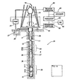
- FIG. 1A illustrates a drilling rig and drill string in which the measurements used with methods of the present invention can be made.
- a land-based platform and derrick assembly 10 are positioned over a wellbore 11 drilled through subsurface formations F.
- the wellbore 11 is formed by rotary drilling in a manner that is known in the art.
- the present invention also finds application in directional drilling applications using hydraulically operated drill motors as well as rotary drilling.
- use of the invention is no way limited to use on land-based rigs.
- a drill string 12 is suspended within the wellbore 11 and includes a drill bit 15 at its lower end.
- the drill string 12 is rotated by a rotary table 16, energized by means not shown, which engages a kelly 17 at the upper end of the drill string.
- the drill string 12 is suspended from a hook 18, attached to a traveling block (also not shown), through the kelly 17 and a rotary swivel 19 which permits rotation of the drill string relative to the hook.
- Drilling fluid or mud 26 is stored in a pit 27 formed at the well site.
- a pump 29 delivers the drilling fluid 26 to the interior of the drill string 12 via a port in the swivel 19, inducing the drilling fluid to flow downwardly through the drill string 12 as indicated by the directional arrow 9.
- the drilling fluid exits the drill string 12 via ports in the drill bit 15, and then circulates upwardly through the region between the outside of the drill string and the wall of the wellbore, called the annulus, as indicated by the direction arrows 32. In this manner, the drilling fluid lubricates the drill bit 15 and carries formation cuttings up to the surface as it is returned to the pit 27 for recirculation.
- the drill string 12 further includes a bottomhole assembly, generally shown at 34 near the drill bit 15 (typically within several drill collar lengths from the drill bit).
- the bottomhole assembly 34 may include capabilities for measuring, processing, and storing information, as well as communicating with the surface.
- the bottomhole assembly (“BHA") 34 thus includes, among other things, a measuring and local communications apparatus 36 for determining and communicating the resistivity of the formation F surrounding the wellbore 11.
- the communications apparatus 36 which includes an azimuthally sensitive resistivity measuring instrument, includes a first pair of transmitting/receiving antennas T, R, as well as a second pair of transmitting/receiving antennas T", R".
- the second pair of antennas T", R" is symmetric with respect to the first pair of antennas T, R.
- the resistivity instrument 36 further includes a controller to control the acquisition of data, as is known in the art.
- the resistivity instrument may be one described more fully in U.S. Patent No. 7,382,135 issued to Li et al. and assigned to the assignee of the present invention.
- the foregoing instrument is used under the trademarks PERISCOPE 15 and PERISCOPE 100, which are trademarks of the assignee of the present invention.
- the PERISCOPE instruments have tilted dipole antennas. Types of interpretation of measurements from such tilted dipole antennas is described more fully in the Omeragic et al. '584 patent referred to above.
- any combination of electromagnetic antennas with dipole moments oriented to be sensitive (i) primarily to "horizontal resistivity” (Rh), which is electrical resistivity of a rock formation measured parallel to the attitude of the formation layer ("bedding plane”); (ii) primarily to “vertical resistivity” (Rv) or resistivity anisotropy, which is electrical resistivity measured perpendicularly to the bedding plane, and (iii) be able to make or synthesize "symmetric” and "anti-symmetric” cross dipole measurements (such measurements are sensitive to the direction and magnitude of formation dip or bedding plane attitude with respect to the wellbore/instrument longitudinal axis).
- Ron horizontal resistivity
- Rv vertical resistivity
- resistivity anisotropy which is electrical resistivity measured perpendicularly to the bedding plane
- the BHA 34 further includes instruments housed within drill collars 38, 39 for performing various other measurement functions, such as measurement of the natural radiation, density (gamma ray or neutron), and pore pressure of the formation F. At least some of the drill collars are equipped with stabilizers 37, as are well known in the art.
- a surface/local communications subassembly 40 is also included in the BHA 34, just above the drill collar 39.
- the subassembly 40 includes a toroidal antenna 42 used for local communication with the resistivity tool 36 (although other known local-communication means may be employed to advantage), and a known type of acoustic telemetry system that communicates with a similar system (not shown) at the earth's surface via signals carried in the drilling fluid or mud.
- the telemetry system in the subassembly 40 includes an acoustic transmitter that generates an acoustic signal in the drilling fluid (a.k.a., "mud-pulse") that is representative of measured downhole parameters.
- mud-pulse acoustic signal in the drilling fluid
- Such telemetry, and related telemetry techniques that impart acoustic signals in the drilling fluid may be generally characterized as modulating the flow of fluid in the drill string or pipe string.
- the generated acoustical signal is received at the surface by transducers represented by reference numeral 31.
- the transducers for example, piezoelectric transducers, convert the received acoustical signals to electronic signals.
- the output of the transducers 31 is coupled to an uphole receiving subsystem 90, which demodulates the transmitted signals.
- the output of the receiving subsystem 90 is then coupled to a computer processor 85 and a recorder 45.
- the processor 85 may be used to determine the formation resistivity profile (among other things) on a "real time" basis while logging or subsequently by accessing the recorded data from the recorder 45.
- the computer processor is coupled to a monitor 92 that employs a graphical user interface ("GUI") through which the measured downhole parameters and particular results derived therefrom (e.g., resistivity profiles) are graphically presented to a user.
- GUI graphical user interface
- An uphole transmitting system 95 is also provided for receiving input commands from the user (e.g., via the GUI in monitor 92), and is operative to selectively interrupt the operation of the pump 29 in a manner that is detectable by transducers 99 in the subassembly 40. In this manner, there is two-way communication between the subassembly 40 and the uphole equipment.
- a suitable subassembly 40 is described in greater detail in U.S. Pat. Nos. 5,235,285 and 5,517,464 , both of which are assigned to the assignee of the present invention.
- alternative acoustic techniques, as well as other telemetry means can be employed for communication with the surface.
- the drill string 12 may be substituted by a "wired" pipe string, which includes a wired signal telemetry channel forming part of each pipe segment, and an electromagnetic coupler disposed on a thread shoulder at each longitudinal end of each pipe segment.
- a wired pipe string which includes a wired signal telemetry channel forming part of each pipe segment, and an electromagnetic coupler disposed on a thread shoulder at each longitudinal end of each pipe segment.
- the drill string 106 that employs a telemetry system 100 in accordance with the present example includes a plurality of interconnected tubular members (described further below) suspended from a derrick and platform assembly 110 by way of a traveling block (not shown) and a hook 118.
- the upper end of the drill string 106 is defined by a kelly joint 117, the uppermost tubular member in the string, which is engaged by a conventional torque-applying means including a rotary table 116 for rotating the kelly joint as well as the entire drill string 106.
- a swivel 119 connects the hook 118 to the kelly joint 117, and permits rotation of the kelly joint and the drill string 106 relative to the hook.
- the lower end of the drill string 106 may include a drill bit 15 which drills through the formation F to create the wellbore 107 as explained above.
- the drill bit is connected for rotation with the drill string 106 in a rotary drilling configuration of the sort described above.
- the drill string 106 as explained above may otherwise employ a "top-drive” configuration wherein a power swivel rotates the drill string instead of a kelly joint and rotary table.
- a power swivel rotates the drill string instead of a kelly joint and rotary table.
- sliding drilling operations may otherwise be conducted with the use of a well known Moineau-type mud motor that converts hydraulic energy from the drilling mud pumped from a mud pit down through the drill string 106 into torque for rotating a drill bit.
- Drilling may furthermore be conducted with so-called “rotary-steerable” systems which are known in the related art.
- the various aspects of the present invention are adapted to each of these configurations and are not limited to conventional rotary drilling operations, although such equipment and methods will be described herein for illustrative purposes.
- the drill string telemetry system 100 can include a cabled communication link 105b having at least two spaced apart adapter subs (e.g., 109a, 109b, 109c) within the drill string 106 and a cable 112 connecting the two adapter subs 109a, 109b for communication of a signal therebetween.
- the cabled communication link 105b can include a communicative coupler permitting the adapter subs to also serve as a component in a piped communication link 105a.
- Measurements from the well logging instrument 34 may be communicated to the surface unit 102 (including a recording unit 45) over the signal channel in the drill string 106 using a cable 103 connected to the swivel 119.
- measurements made from instruments such as those described above are processed to determine horizontal resistivity (apparent resistivity measured transversely to the thickness of a formation layer), vertical resistivity (resistivity measured along the direction of the thickness of a formation layer) and dip (attitude of the layers with respect to a selected axial reference).
- the 1-D parametric inversion used to interpret wireline triaxial induction measurements is based on a "layer-cake" (substantially planar, parallel bedded formations) transversely isotropic (TI) formation model.
- TI transversely isotropic
- an inversion procedure according to the present invention may determine horizontal and vertical resistivity, Rh and Rv, respectively, formation dip (direction and magnitude) and thicknesses of all formation layers traversed by the well logging instrument.
- Methods according to the invention take advantage of the fact that different measurements made by the instrument are predominantly sensitive to different formation model parameters.
- a multi-step inversion procedure according to the invention typically includes the following general steps, which will be individually explained further below.
- each of the above general steps (1) through (6) is itself an inversion procedure.
- the results of each individual inversion step (1) through (6) may be used as the initial model for each subsequent inversion step in the above procedure.
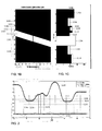
- FIG. 1B shows a 1-D formation model having dipping formations, shown at 102-118.
- the synthetic response of a well logging instrument disposed in a simulated vertical well 100 penetrating such formations 102-118 was generated, and the synthetic response was used to perform an inversion, the results of which are shown in FIG. 7 .
- "dip" calculated using methods according to the present invention represents the attitude of the formation layers with respect to the axis of the wellbore and/or well logging instrument. In cases where the wellbore is in fact geodetically vertical, the determined dip will represent the geodetic dip.
- the determined dip may be converted to geodetic dip by adjusting for the wellbore geodetic trajectory.
- Such trajectory is typically measured substantially along the entire wellbore using directional sensors (e.g., a combination of triaxial magnetometer and triaxial accelerometer).
- General procedures for estimating initial formation layer (“bed") boundary positions from resistivity measurements include selecting a resistivity response (R).
- the response R may be obtained using the PERISCOPE instrument described above or any longitudinal magnetic dipole electromagnetic instrument and selecting one of the resistivity response curves, for example, phase shift.
- the logarithm thereof, log(R) is then calculated.
- the derivative of log(R) with respect to axial position (measured depth) may be calculated.
- the peaks on the derivative curve may be selected as the bed boundaries.
- bed thicknesses are examined. If the thinnest bed is below a predefined cutoff or threshold value, then the following procedures may be used. If one of the adjacent beds is thick (e.g., above the threshold thickness), the selected bed boundary may be moved toward the thick bed to increase the thickness of the layer having below the threshold thickness (the "thin bed"). If both adjacent layers are thick, the bed boundary may be moved toward the bed having lower resistivity contrast with respect to the thin bed. If both adjacent beds are thin (below the threshold thickness), remove the bed boundary with lower resistivity contrast with reference to the thin bed under examination. The foregoing process may be repeated until all the thin beds are removed from the initial estimate. If some of the layers are too thick (i.e. > 3 meters), additional bed boundaries may be added as may be appropriate.
- the resistivity of a selected response (e.g., the phase response identified above) is determined at the axial middle of the beds. For each bed, such value is the initial estimated value of horizontal resistivity, Rh.
- An assumption may then be made about the formation dip using external information, e.g., image measurements. If no such external information is available, zero dip can be chosen as the initial estimate.
- FIG. 2 shows the log(R) response of the a 28 inch spacing phase response at curve 120 and the selected bed boundaries at 124 using the foregoing procedure.
- the derivative of log(R) is shown at 122
- the foregoing procedure identifies all the actual bed boundaries, but it may also identify false boundaries.
- the estimates of bed boundary axial positions are close to the actual model positions.
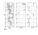
- FIG. 3 shows the initial formation estimate derived as explained above with reference to FIG. 2 and FIG. 3 compared with the actual formation model used.
- Rh, Rv and Dip values are plotted along MD ("measured depth" or axial position along the length of the wellbore).
- Model input values of Rh are shown at curve 126
- model input Rv values are shown at curve 128, initial Rh and Rv are shown at curves 127 and 130, respectively.
- Model dip is shown in the second track of the log presentation at curve 132 and initial dip is shown at curve 134.
- Discontinuities in Rh and Rv typically indicate positions of bed boundaries.
- the initial estimate of Rh appears very close to the actual model value thereof.
- Rv and dip values however are quite different between the initial estimate determined using the above procedure and the actual model.
- the global factor is used to define accuracy of the inverted model accuracy in this note.
- the above outlined methodology does not include anisotropy and directional measurements, and has a limitation in that if Rh is not changing, it will not identify Rv discontinuities.
- Anisotropy and directional measurements e.g., appropriate measurement channels from the PERISCOPE instrument
- depth shifting can be applied and performed on individual pairs of measurements
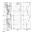
- anisotropy responses are the most sensitive to Rv. In this step they are used to invert for Rv only, fixing Rh, dip and positions of the bed boundaries from the previous step. The inverted results are shown in FIG. 5 , using the same curve numbering notation as for FIGS. 3 and 4 . A significant improvement in Rv values and global model accuracy can be observed.
- the estimates of formation Rh, Rv and dip are typically already close to a final solution, and the present steps, 5 through 7, represent a "fine tuning.” It is computationally the most expensive, but typically the step requires only a small number of iterations to reach convergence or minimization of a cost function.
- the results are shown in FIG. 7 .
- the original model is reconstructed fully, so restarting the inversion after model perturbation (step 7) was not necessary.
- the inversion may become "trapped" at a local minimum in the cost function. In such cases the inversion can be resumed by perturbing the final model obtained when the cost function is minimized.
- the invention also provides a method which takes different key elements from to define log quality controls to enable the user to evaluate the reliability of the inversion results.
- QC indicators Three categories of elements may be considered for the purpose of constructing QC indicators, in certain exemplary embodiments: (a) model validity, (b) data fit, and (c) uncertainty of inversion parameters. Each of these is described in more detail below.
- Two exemplary factors that can be used to compute the non-1D factor are standard deviation in estimated formation dip and variation of formation azimuth angle.
- standard deviation as previously stated, the 1-D model assumes constant formation dip within the processing window. Dip standard deviation within the processing window is a good indicator of the degree of deviation from the 1-D approximation. The dip value can be obtained from other measurements, or may be obtained by any results from the PERISCOPE instrument measurement inversion.
- a LQC indicator may be defined based on the dip standard deviation within the processing window.
- LQC dip_std 1 - min ⁇ dip_std cutoff_dip_std ⁇ 1 power_dip_std cutoff_dip_std and power_dip_std are scaling factors determined from testing data.
- the apparent azimuth angle in a "top of hole” coordinate system is given by the PERISCOPE instrument measurement channel (known as DANG angle).
- DANG_std is the standard deviation of DANG values within the processing window. cutoff_DANG_std and power_DANG_std are scaling factors
- Inversion residual is the cost function which the inversion is intended to minimize.
- the cost function is essentially a combination of data misfit for measurement used in the inversion and the regularization terms.
- Fitting errors for part or all of the available ARC or PERISCOPE instrument measurements may be defined as:
- the 3 categories of QC elements described above may be combined to define inversion quality for Rh, Rv, Dip, Azimuth as well as the global quality.
- Rh uncertainty R h_unc , inversion residual ⁇ , data fitting for ARC (or PERISCOPE) misfit_ARC and cost_ ARC
- the final Rh quality LQC Rh max LQC Rh ⁇ 1 ⁇ LQC Rh ⁇ 2
- LQC for true dip Combining dip uncertainty dip true_unc , inversion residual C, data fitting for directional and anisotropy channels( misfit_DXA and cost_ DXA )
- LQC true_dip ⁇ max LQC true_dip ⁇ 1 ⁇ LQC true_dip ⁇ 2 ⁇ LQC dip_std dip app ⁇ 2 0 max LQC true_dip ⁇ 1 ⁇ LQC true_dip ⁇ 2 ⁇ LQC dip_std ⁇ LQC DANG_std else
- LQC for true dip azimuth Combining azimuth uncertainty azi true_unc , inversion residualC, data fitting for directional and anisotropy channels( misfit_DXA and cos t _ DXA )
- LQC true_azi ⁇ 2 1 - min ⁇ azi true_unc ⁇ C ⁇ cost _ DXA cutoff true_azi_unc_ cost ⁇ 1 power_misfit_ DXA ⁇ LQC dip_std ⁇ LQC DANG_std
- LQC true_azi ⁇ max LQC true_azi ⁇ 1 ⁇ LQC true_azi ⁇ 2 ⁇ LQC dip_std if dip app ⁇ 2 0 max LQC true_azi ⁇ 1 ⁇ LQC true_azi ⁇ 2 ⁇ LQC dip_std ⁇ LQC DANG_std else
- Dip and azimuth effect may be discounted in cases of isotropic and homogeneous rock formations.
- the resulting qualities may all be ranged from 0 to 1.
- the values may be converted into a color map in which the color gradually changes from red to green as the quality values increases from 0 to 1. In general green indicates good quality and red color will initiate an alert to the system operator. Any other type of display may be used to indicate the quality as well as color, such as a curve scaled between zero and unity and displayed with respect to depth.
- FIG. 8 shows a field data example.
- the first three tracks shows the inverted formation model parameters Rh, Rv, Dip, Azimuth.
- the last track shows the QC (quality control) for Rh, Rv, Dip, azimuth and the overall inversion quality.
- the inversion encountered some difficulties.
- the Rh and Rv curves showed some spikes and the quality was relatively low.
- the inverted dip and azimuth showed some reduced QC (indicated by yellow on the color map, or reductions in the Global Confidence color map 136 for example) but the determined Rh and Rv are still very reliable.
- the Global Confidence may be presented in the form of a color or gray scale map or a curve at the discretion of the system designer or user.
- One technique for managing borehole effect is to exclude the measurements that have large borehole effect, and perform the inversion with measurements that have more limited borehole effect (typically those having larger transmitter to receiver spacing), or conversely, excluding from the inversion procedure those responses from relatively short spaced transmitter/receiver combinations.
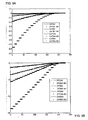
- FIGS. 9A through 9D show a synthetic example, comparing tool responses with and without large borehole effect.
- borehole effect is small for most channels except for the curves marked DPS964 and APS594, which are reflect response of relatively short spaced transmitter-receiver combinations.
- FIG. 10 shows the inversion results when curves DPS964 and APS594 are included.
- the inverted Rv is substantially different from the Rv model value.
- response curves DPS964 and APS594 were excluded from the inversion, and the new results are shown in FIG. 11 .
- the inversion results are much closer to the model values.
- Methods according to the invention may provide faster inversion results than methods used for wireline triaxial induction, thus making possible calculation of inversion results substantially in real time during drilling a wellbore, if so desired.
Landscapes
- Life Sciences & Earth Sciences (AREA)
- Engineering & Computer Science (AREA)
- Remote Sensing (AREA)
- Physics & Mathematics (AREA)
- Environmental & Geological Engineering (AREA)
- Geology (AREA)
- General Life Sciences & Earth Sciences (AREA)
- General Physics & Mathematics (AREA)
- Geophysics (AREA)
- Electromagnetism (AREA)
- Geophysics And Detection Of Objects (AREA)
- Investigating Or Analyzing Materials By The Use Of Magnetic Means (AREA)
Applications Claiming Priority (3)
| Application Number | Priority Date | Filing Date | Title |
|---|---|---|---|
| US24879009P | 2009-10-05 | 2009-10-05 | |
| US32628710P | 2010-04-21 | 2010-04-21 | |
| US12/888,232 US8433518B2 (en) | 2009-10-05 | 2010-09-22 | Multilevel workflow method to extract resistivity anisotropy data from 3D induction measurements |
Publications (3)
| Publication Number | Publication Date |
|---|---|
| EP2320251A2 true EP2320251A2 (fr) | 2011-05-11 |
| EP2320251A3 EP2320251A3 (fr) | 2013-07-10 |
| EP2320251B1 EP2320251B1 (fr) | 2019-01-02 |
Family
ID=43829380
Family Applications (1)
| Application Number | Title | Priority Date | Filing Date |
|---|---|---|---|
| EP10013287.7A Active EP2320251B1 (fr) | 2009-10-05 | 2010-10-04 | Procédé de flux de travail multi-niveaux permettant d'extraire des données d'anisotropie de résistivité à partir de mesures d'induction 3D |
Country Status (4)
| Country | Link |
|---|---|
| US (2) | US8433518B2 (fr) |
| EP (1) | EP2320251B1 (fr) |
| CN (1) | CN102031964B (fr) |
| BR (1) | BRPI1004097A2 (fr) |
Cited By (9)
| Publication number | Priority date | Publication date | Assignee | Title |
|---|---|---|---|---|
| US8433518B2 (en) | 2009-10-05 | 2013-04-30 | Schlumberger Technology Corporation | Multilevel workflow method to extract resistivity anisotropy data from 3D induction measurements |
| EP2788795A4 (fr) * | 2011-12-06 | 2015-09-30 | Services Petroliers Schlumberger | Système et procédé de production de mesures de profils d'anticipation lors d'une opération de forage |
| WO2015153280A1 (fr) * | 2014-03-29 | 2015-10-08 | Schlumberger Canada Limited | Mesures de propagation directionnelle à compensation de gain |
| WO2015153294A1 (fr) * | 2014-03-30 | 2015-10-08 | Schlumberger Canada Limited | Mesurages à compensation de gain au moyen d'antennes inclinées |
| EP2831644A4 (fr) * | 2012-03-27 | 2015-10-21 | Services Petroliers Schlumberger | Traitement anisotropique dans des puits peu inclinés |
| US9541666B2 (en) | 2014-03-29 | 2017-01-10 | Schlumberger Technology Corporation | Electromagnetic logging while drilling tool |
| FR3062674A1 (fr) * | 2017-02-06 | 2018-08-10 | Halliburton Energy Services, Inc. | Inversion de distance jusqu'a la limite de base (dtbb) multi-couche avec de multiples valeurs supposees initiales |
| US10345475B2 (en) | 2013-04-02 | 2019-07-09 | Schlumberger Technology Corporation | Extended 1D inversion of electromagnetic measurements for formation evaluation |
| US11204438B2 (en) | 2019-10-25 | 2021-12-21 | Schlumberger Technology Corporation | Determining anisotropic subsurface properties with electromagnetic measurements |
Families Citing this family (68)
| Publication number | Priority date | Publication date | Assignee | Title |
|---|---|---|---|---|
| US7659722B2 (en) | 1999-01-28 | 2010-02-09 | Halliburton Energy Services, Inc. | Method for azimuthal resistivity measurement and bed boundary detection |
| CN101501297B (zh) * | 2006-07-11 | 2013-10-16 | 哈里伯顿能源服务公司 | 模块化地质导向工具组件 |
| US8593147B2 (en) | 2006-08-08 | 2013-11-26 | Halliburton Energy Services, Inc. | Resistivity logging with reduced dip artifacts |
| US8274289B2 (en) | 2006-12-15 | 2012-09-25 | Halliburton Energy Services, Inc. | Antenna coupling component measurement tool having rotating antenna configuration |
| AU2008348131B2 (en) | 2008-01-18 | 2011-08-04 | Halliburton Energy Services, Inc. | EM-guided drilling relative to an existing borehole |
| GB2509450A (en) | 2011-10-31 | 2014-07-02 | Schlumberger Holdings | Inversion-based workflow for processing nuclear density images in high-angle and horizontal wells |
| CN102635347B (zh) * | 2012-03-30 | 2014-12-10 | 中国电子科技集团公司第二十二研究所 | 一种定量将薄互地层等效成水平和垂直电阻率的方法 |
| CA2884681A1 (fr) | 2012-09-12 | 2014-03-20 | Halliburton Energy Services, Inc. | Procede et systeme pour determiner en temps reel l'anisotropie, le pendage et la rencontre d'une formation au moyen de donnees de mci |
| CA2911648C (fr) | 2013-06-13 | 2020-04-14 | Halliburton Energy Services, Inc. | Procedes et systemes d'outil de visualisation de direction de diagraphie en cours de forage (lwd) |
| BR112016001934A2 (pt) * | 2013-09-10 | 2017-08-29 | Halliburton Energy Services Inc | Método para exploração e produção de petróleo e gás, dispositivo de armazenamento legível por máquina não transitório, e, sistema para exploração e produção de petróleo e gás |
| US10370963B2 (en) * | 2013-09-30 | 2019-08-06 | Schlumberger Technology Corporation | Method for selecting bed boundaries and log squaring using electromagnetic measurements |
| US10323498B2 (en) | 2013-10-01 | 2019-06-18 | Schlumberger Technology Corporation | Methods, computer-readable media, and systems for applying 1-dimensional (1D) processing in a non-1D formation |
| WO2015051123A1 (fr) * | 2013-10-02 | 2015-04-09 | Schlumberger Canada Limited | Procédé et appareil de détermination de propriétés de formation utilisant des mesures électromagnétiques non directionnelles dans des puits à grande déviation ou horizontaux |
| WO2015051300A1 (fr) * | 2013-10-04 | 2015-04-09 | Halliburton Energy Services, Inc. | Détermination du pendage/de l'azimut d'une formation au moyen de données d'induction à composants multiples |
| US10914861B2 (en) | 2013-10-04 | 2021-02-09 | Schlumberger Technology Corporation | Inversion-based workflow for consistent interpretation of nuclear density images in horizontal wells |
| EP2898353A4 (fr) * | 2013-11-08 | 2016-08-10 | Halliburton Energy Services Inc | Estimation de formation tridimensionnelle en utilisant des outils à induction à composants multiples |
| US10571595B2 (en) | 2014-01-27 | 2020-02-25 | Schlumberger Technology Corporation | Workflow for navigation with respect to oil-water contact using deep directional resistivity measurements |
| WO2015137921A1 (fr) | 2014-03-11 | 2015-09-17 | Halliburton Energy Services, Inc. | Systèmes et procédés de diagraphie par induction multicomposant en utilisant l'inversion du modèle mélangé |
| MX369871B (es) | 2014-04-03 | 2019-11-25 | Halliburton Energy Services Inc | Metodos y sistemas de registro de induccion con componentes multiples utilizando inversion de frecuencia seleccionada. |
| CN104088630B (zh) * | 2014-07-09 | 2016-08-10 | 中国石油集团长城钻探工程有限公司 | 随钻方位电阻率测井仪器获取地层边界距离的方法 |
| US10401529B2 (en) | 2014-10-17 | 2019-09-03 | Halliburton Energy Services, Inc. | Fast-changing dip formation resistivity estimation |
| CN104612661B (zh) * | 2014-12-09 | 2018-09-11 | 中国科学院声学研究所 | 一种随钻电磁波测井装置和方法 |
| GB2547829B (en) * | 2014-12-18 | 2021-07-28 | Halliburton Energy Services Inc | Shoulder effect reduction |
| US10620334B2 (en) | 2014-12-31 | 2020-04-14 | Halliburton Energy Services, Inc. | Modifying magnetic tilt angle using a magnetically anisotropic material |
| US10451769B2 (en) | 2015-01-26 | 2019-10-22 | Schlumberger Technology Corporation | Method for determining petrophysical properties from logging measurements |
| CN106285655B (zh) * | 2015-06-05 | 2020-03-10 | 中国石油天然气股份有限公司 | 砂岩地层测井评估方法 |
| BR112017028114A2 (pt) * | 2015-07-28 | 2018-08-28 | Halliburton Energy Services Inc | método e sistema para avaliação de formação em tempo real. |
| CN105089663B (zh) * | 2015-07-31 | 2017-11-07 | 中国石油天然气集团公司 | 一种大斜度/水平井地层电阻率各向异性校正方法 |
| GB2556609B (en) * | 2015-09-30 | 2021-07-14 | Schlumberger Technology Bv | Methods and systems to analyze bed boundary detection |
| US11092713B2 (en) | 2015-11-04 | 2021-08-17 | Schlumberger Technology Corporation | Compensated azimuthally invariant electromagnetic logging measurements |
| CN108291978B (zh) * | 2015-11-04 | 2020-12-01 | 斯伦贝谢技术有限公司 | 电磁测井测量的实部和虚部 |
| US10295696B2 (en) | 2015-11-12 | 2019-05-21 | Halliburton Energy Services, Inc. | Multi-component induction logging data processing in non-circular boreholes |
| US11237288B2 (en) | 2016-03-30 | 2022-02-01 | Halliburton Energy Services, Inc. | Verifying measurements of elastic anisotropy parameters in an anisotropic wellbore environment |
| US10324432B2 (en) | 2016-04-21 | 2019-06-18 | Baker Hughes, A Ge Company, Llc | Estimation of electromagnetic tool sensitivity range |
| AU2017263252B2 (en) | 2016-05-08 | 2023-02-02 | Schlumberger Technology B.V. | Methods and systems employing look-around and look-ahead inversion of downhole measurements |
| CN106285661B (zh) * | 2016-08-24 | 2020-01-07 | 中国石油天然气股份有限公司 | 一种基于判定指数的低阻油层识别方法及装置 |
| CN106522932B (zh) * | 2016-09-28 | 2019-07-09 | 中国石油天然气股份有限公司 | 获取水平井各向异性地层电阻率的方法及装置 |
| WO2018075007A1 (fr) | 2016-10-18 | 2018-04-26 | Halliburton Energy Services, Inc. | Diagraphie mci améliorée destinée au traitement de mesures de fond de trou |
| CN108547611B (zh) * | 2018-03-01 | 2022-02-11 | 杭州迅美科技有限公司 | 水平井复杂环境随钻电磁波电阻率测井快速仿真方法 |
| US11150373B2 (en) * | 2018-04-27 | 2021-10-19 | Schlumberger Technology Corporation | Determining dielectric constant and resistivity with induction measurement |
| CN110552689A (zh) * | 2018-05-15 | 2019-12-10 | 中国石油化工股份有限公司 | 一种确定随钻仪器到地层边界距离的方法 |
| US11573159B2 (en) | 2019-01-08 | 2023-02-07 | Saudi Arabian Oil Company | Identifying fracture barriers for hydraulic fracturing |
| EP3942145B1 (fr) | 2019-03-18 | 2025-02-19 | Magnetic Variation Services, LLC | Orientation d'un puits de forage à l'aide de cartes thermiques stratigraphiques non ajustées |
| US10830027B2 (en) | 2019-04-15 | 2020-11-10 | Saudi Arabian Oil Company | System and method to evaluate kerogen-rich shale |
| CN109917466B (zh) * | 2019-04-24 | 2020-05-26 | 中南大学 | 一种基于电磁场垂直分量的电阻率测量方法 |
| US11946360B2 (en) * | 2019-05-07 | 2024-04-02 | Magnetic Variation Services, Llc | Determining the likelihood and uncertainty of the wellbore being at a particular stratigraphic vertical depth |
| US11492541B2 (en) | 2019-07-24 | 2022-11-08 | Saudi Arabian Oil Company | Organic salts of oxidizing anions as energetic materials |
| US11319478B2 (en) | 2019-07-24 | 2022-05-03 | Saudi Arabian Oil Company | Oxidizing gasses for carbon dioxide-based fracturing fluids |
| US11352548B2 (en) | 2019-12-31 | 2022-06-07 | Saudi Arabian Oil Company | Viscoelastic-surfactant treatment fluids having oxidizer |
| US11339321B2 (en) | 2019-12-31 | 2022-05-24 | Saudi Arabian Oil Company | Reactive hydraulic fracturing fluid |
| WO2021138355A1 (fr) | 2019-12-31 | 2021-07-08 | Saudi Arabian Oil Company | Fluides de fracturation à tensioactif viscoélastique ayant un oxydant |
| US11473009B2 (en) | 2020-01-17 | 2022-10-18 | Saudi Arabian Oil Company | Delivery of halogens to a subterranean formation |
| US11268373B2 (en) | 2020-01-17 | 2022-03-08 | Saudi Arabian Oil Company | Estimating natural fracture properties based on production from hydraulically fractured wells |
| US11473001B2 (en) | 2020-01-17 | 2022-10-18 | Saudi Arabian Oil Company | Delivery of halogens to a subterranean formation |
| US11365344B2 (en) | 2020-01-17 | 2022-06-21 | Saudi Arabian Oil Company | Delivery of halogens to a subterranean formation |
| US11549894B2 (en) | 2020-04-06 | 2023-01-10 | Saudi Arabian Oil Company | Determination of depositional environments |
| US11578263B2 (en) | 2020-05-12 | 2023-02-14 | Saudi Arabian Oil Company | Ceramic-coated proppant |
| WO2021247123A1 (fr) * | 2020-06-05 | 2021-12-09 | Halliburton Energy Services, Inc. | Localisation de trous de forages par rapport à des objets et à des formations souterraines |
| US11542815B2 (en) | 2020-11-30 | 2023-01-03 | Saudi Arabian Oil Company | Determining effect of oxidative hydraulic fracturing |
| US12071589B2 (en) | 2021-10-07 | 2024-08-27 | Saudi Arabian Oil Company | Water-soluble graphene oxide nanosheet assisted high temperature fracturing fluid |
| US12025589B2 (en) | 2021-12-06 | 2024-07-02 | Saudi Arabian Oil Company | Indentation method to measure multiple rock properties |
| US11885790B2 (en) | 2021-12-13 | 2024-01-30 | Saudi Arabian Oil Company | Source productivity assay integrating pyrolysis data and X-ray diffraction data |
| US12012550B2 (en) | 2021-12-13 | 2024-06-18 | Saudi Arabian Oil Company | Attenuated acid formulations for acid stimulation |
| CN116122794B (zh) * | 2023-01-10 | 2024-06-11 | 中国石油大学(华东) | 一种复杂地层环境阵列电阻率测井解耦降维正演方法 |
| US12326078B2 (en) | 2023-07-19 | 2025-06-10 | Halliburton Energy Services, Inc. | Effective resistivity models for geosteering decisions |
| CN117166987B (zh) * | 2023-09-28 | 2024-03-19 | 中勘地球物理有限责任公司 | 一种基于无线电波反射的插入式矿产勘查装置 |
| US20250341652A1 (en) * | 2024-05-01 | 2025-11-06 | Halliburton Energy Services, Inc. | Neighboring Resistivity Anisotropy Determination |
| CN118152896B (zh) * | 2024-05-11 | 2024-07-16 | 西安石油大学 | 一种水平井钻头距砂岩储层纵向边界距离预测方法及装置 |
Citations (7)
| Publication number | Priority date | Publication date | Assignee | Title |
|---|---|---|---|---|
| US5235285A (en) | 1991-10-31 | 1993-08-10 | Schlumberger Technology Corporation | Well logging apparatus having toroidal induction antenna for measuring, while drilling, resistivity of earth formations |
| US5517464A (en) | 1994-05-04 | 1996-05-14 | Schlumberger Technology Corporation | Integrated modulator and turbine-generator for a measurement while drilling tool |
| US6594584B1 (en) | 1999-10-21 | 2003-07-15 | Schlumberger Technology Corporation | Method for calculating a distance between a well logging instrument and a formation boundary by inversion processing measurements from the logging instrument |
| US6998844B2 (en) | 2002-04-19 | 2006-02-14 | Schlumberger Technology Corporation | Propagation based electromagnetic measurement of anisotropy using transverse or tilted magnetic dipoles |
| US7040415B2 (en) | 2003-10-22 | 2006-05-09 | Schlumberger Technology Corporation | Downhole telemetry system and method |
| US7382135B2 (en) | 2003-05-22 | 2008-06-03 | Schlumberger Technology Corporation | Directional electromagnetic wave resistivity apparatus and method |
| US7536261B2 (en) | 2005-04-22 | 2009-05-19 | Schlumberger Technology Corporation | Anti-symmetrized electromagnetic measurements |
Family Cites Families (9)
| Publication number | Priority date | Publication date | Assignee | Title |
|---|---|---|---|---|
| US5329448A (en) * | 1991-08-07 | 1994-07-12 | Schlumberger Technology Corporation | Method and apparatus for determining horizontal conductivity and vertical conductivity of earth formations |
| US6163155A (en) * | 1999-01-28 | 2000-12-19 | Dresser Industries, Inc. | Electromagnetic wave resistivity tool having a tilted antenna for determining the horizontal and vertical resistivities and relative dip angle in anisotropic earth formations |
| US6502036B2 (en) * | 2000-09-29 | 2002-12-31 | Baker Hughes Incorporated | 2-D inversion of multi-component induction logging data to resolve anisotropic resistivity structure |
| US6969994B2 (en) * | 2001-09-26 | 2005-11-29 | Schlumberger Technology Corporation | Directional electromagnetic measurements insensitive to dip and anisotropy |
| US7091877B2 (en) * | 2003-10-27 | 2006-08-15 | Schlumberger Technology Corporation | Apparatus and methods for determining isotropic and anisotropic formation resistivity in the presence of invasion |
| US7317991B2 (en) * | 2005-01-18 | 2008-01-08 | Baker Hughes Incorporated | Multicomponent induction measurements in cross-bedded and weak anisotropy approximation |
| US8129993B2 (en) * | 2007-07-10 | 2012-03-06 | Schlumberger Technology Corporation | Determining formation parameters using electromagnetic coupling components |
| CN101289935B (zh) * | 2008-06-11 | 2012-02-08 | 中国石油集团钻井工程技术研究院 | 一种近钻头地质导向探测系统 |
| US8433518B2 (en) | 2009-10-05 | 2013-04-30 | Schlumberger Technology Corporation | Multilevel workflow method to extract resistivity anisotropy data from 3D induction measurements |
-
2010
- 2010-09-22 US US12/888,232 patent/US8433518B2/en active Active
- 2010-10-04 EP EP10013287.7A patent/EP2320251B1/fr active Active
- 2010-10-04 BR BRPI1004097-8A patent/BRPI1004097A2/pt not_active IP Right Cessation
- 2010-10-08 CN CN201010512836.1A patent/CN102031964B/zh active Active
-
2013
- 2013-04-30 US US13/874,275 patent/US9057797B2/en active Active
Patent Citations (7)
| Publication number | Priority date | Publication date | Assignee | Title |
|---|---|---|---|---|
| US5235285A (en) | 1991-10-31 | 1993-08-10 | Schlumberger Technology Corporation | Well logging apparatus having toroidal induction antenna for measuring, while drilling, resistivity of earth formations |
| US5517464A (en) | 1994-05-04 | 1996-05-14 | Schlumberger Technology Corporation | Integrated modulator and turbine-generator for a measurement while drilling tool |
| US6594584B1 (en) | 1999-10-21 | 2003-07-15 | Schlumberger Technology Corporation | Method for calculating a distance between a well logging instrument and a formation boundary by inversion processing measurements from the logging instrument |
| US6998844B2 (en) | 2002-04-19 | 2006-02-14 | Schlumberger Technology Corporation | Propagation based electromagnetic measurement of anisotropy using transverse or tilted magnetic dipoles |
| US7382135B2 (en) | 2003-05-22 | 2008-06-03 | Schlumberger Technology Corporation | Directional electromagnetic wave resistivity apparatus and method |
| US7040415B2 (en) | 2003-10-22 | 2006-05-09 | Schlumberger Technology Corporation | Downhole telemetry system and method |
| US7536261B2 (en) | 2005-04-22 | 2009-05-19 | Schlumberger Technology Corporation | Anti-symmetrized electromagnetic measurements |
Non-Patent Citations (4)
| Title |
|---|
| HABASHY, T.; ABUBAKAR, A.: "A general framework for constraint minimization for the inversion of electromagnetic measurements", PROGRESS IN ELECTROMAGNETICS RESEARCH (PIER), vol. 46, 2004, pages 265 - 312 |
| KRIEGHAUSER ET AL., A NEW MULTICOMPONENT INDUCTION TOOL TO RESOLVE ANISOTROPIC FORMATION, 2000, pages 4151 |
| ROSTHAL, R.; BARBER, T.; BONNER, S.; CHEN, K.C.; DAVYDYCHEVA, S.; HAZEN, G.; HOMAN, D.; KIBBE, S.; MINERBO, G.; SCHLEIN, R.: "Field tests of an experimental fully triaxial induction tool", SPWLA ANNUAL LOGGING SYMPOSIUM, vol. 22-25, June 2003 (2003-06-01) |
| WANG, H.; BARBER, T.; ROSTHAL, R.; TABANOU, J.; ANDERSON, B.; HABASHY, T.: "Fast and rigorous inversion of triaxial induction logging data to determine formation resistivity anisotropy, bed boundary position, relative dip and azimuth angles", SEG ANNUAL MEETING, 27 October 2003 (2003-10-27) |
Cited By (16)
| Publication number | Priority date | Publication date | Assignee | Title |
|---|---|---|---|---|
| US9057797B2 (en) | 2009-10-05 | 2015-06-16 | Schlumberger Technology Corporation | Multilevel workflow method to extract resistivity anisotropy data from three-dimensional induction measurements |
| US8433518B2 (en) | 2009-10-05 | 2013-04-30 | Schlumberger Technology Corporation | Multilevel workflow method to extract resistivity anisotropy data from 3D induction measurements |
| EP2788795A4 (fr) * | 2011-12-06 | 2015-09-30 | Services Petroliers Schlumberger | Système et procédé de production de mesures de profils d'anticipation lors d'une opération de forage |
| RU2615219C2 (ru) * | 2012-03-27 | 2017-04-04 | Шлюмбергер Текнолоджи Б.В. | Обработка анизотропии в пологих скважинах |
| EP2831644A4 (fr) * | 2012-03-27 | 2015-10-21 | Services Petroliers Schlumberger | Traitement anisotropique dans des puits peu inclinés |
| US9429675B2 (en) | 2012-03-27 | 2016-08-30 | Schlumberger Technology Corporation | Anisotropy processing in low angle wells |
| US10345475B2 (en) | 2013-04-02 | 2019-07-09 | Schlumberger Technology Corporation | Extended 1D inversion of electromagnetic measurements for formation evaluation |
| US10215878B2 (en) | 2014-03-29 | 2019-02-26 | Schlumberger Technology Corporation | Gain compensated directional propagation measurements |
| US9541666B2 (en) | 2014-03-29 | 2017-01-10 | Schlumberger Technology Corporation | Electromagnetic logging while drilling tool |
| US9581721B2 (en) | 2014-03-29 | 2017-02-28 | Schlumberger Technology Corporation | Method for making downhole electromagnetic logging while drilling measurements |
| US9448324B2 (en) | 2014-03-29 | 2016-09-20 | Schlumberger Technology Corporation | Gain compensated directional propagation measurements |
| WO2015153280A1 (fr) * | 2014-03-29 | 2015-10-08 | Schlumberger Canada Limited | Mesures de propagation directionnelle à compensation de gain |
| WO2015153294A1 (fr) * | 2014-03-30 | 2015-10-08 | Schlumberger Canada Limited | Mesurages à compensation de gain au moyen d'antennes inclinées |
| US10302805B2 (en) | 2014-03-30 | 2019-05-28 | Schlumberger Technology Corporation | System and methods for obtaining compensated electromagnetic measurements |
| FR3062674A1 (fr) * | 2017-02-06 | 2018-08-10 | Halliburton Energy Services, Inc. | Inversion de distance jusqu'a la limite de base (dtbb) multi-couche avec de multiples valeurs supposees initiales |
| US11204438B2 (en) | 2019-10-25 | 2021-12-21 | Schlumberger Technology Corporation | Determining anisotropic subsurface properties with electromagnetic measurements |
Also Published As
| Publication number | Publication date |
|---|---|
| EP2320251B1 (fr) | 2019-01-02 |
| US20110231098A1 (en) | 2011-09-22 |
| US9057797B2 (en) | 2015-06-16 |
| CN102031964A (zh) | 2011-04-27 |
| US20140149040A1 (en) | 2014-05-29 |
| BRPI1004097A2 (pt) | 2013-02-13 |
| US8433518B2 (en) | 2013-04-30 |
| EP2320251A3 (fr) | 2013-07-10 |
| CN102031964B (zh) | 2015-09-30 |
Similar Documents
| Publication | Publication Date | Title |
|---|---|---|
| EP2320251B1 (fr) | Procédé de flux de travail multi-niveaux permettant d'extraire des données d'anisotropie de résistivité à partir de mesures d'induction 3D | |
| EP3114313B1 (fr) | Technique d'inversion pour positionnement de puits et caractérisation de réservoir en temps réel | |
| US8364404B2 (en) | System and method for displaying data associated with subsurface reservoirs | |
| US6984983B2 (en) | System and method for evaluation of thinly laminated earth formations | |
| EP2663737B1 (fr) | Modélisation de profil d'écoulement pour puits | |
| EP3080389B1 (fr) | Détermination et affichage de résistivité apparente de données électromagnétiques transitoires de fond de trou | |
| US8892362B2 (en) | System and method for improving surface electromagnetic surveys | |
| US10139517B2 (en) | Hybrid image of earth formation based on transient electromagnetc measurements | |
| US10301935B2 (en) | MCI logging for processing downhole measurements | |
| CN104054007B (zh) | 进行地下作业时用于分析地层特性的方法和系统 | |
| AU2017263252B2 (en) | Methods and systems employing look-around and look-ahead inversion of downhole measurements | |
| US20170254921A1 (en) | Fast-changing dip formation resistivity estimation | |
| US11574459B2 (en) | Distance-to-bed-boundary inversion solution pixelation | |
| NO20241191A1 (en) | Reservoir properties derived using ultra-deep resistivity inversion data | |
| WO2016057312A1 (fr) | Correction de fuite de courant d'électrodes de surveillance dans des outils galvaniques |
Legal Events
| Date | Code | Title | Description |
|---|---|---|---|
| PUAI | Public reference made under article 153(3) epc to a published international application that has entered the european phase |
Free format text: ORIGINAL CODE: 0009012 |
|
| AK | Designated contracting states |
Kind code of ref document: A2 Designated state(s): AL AT BE BG CH CY CZ DE DK EE ES FI FR GB GR HR HU IE IS IT LI LT LU LV MC MK MT NL NO PL PT RO RS SE SI SK SM TR |
|
| AX | Request for extension of the european patent |
Extension state: BA ME |
|
| PUAL | Search report despatched |
Free format text: ORIGINAL CODE: 0009013 |
|
| AK | Designated contracting states |
Kind code of ref document: A3 Designated state(s): AL AT BE BG CH CY CZ DE DK EE ES FI FR GB GR HR HU IE IS IT LI LT LU LV MC MK MT NL NO PL PT RO RS SE SI SK SM TR |
|
| AX | Request for extension of the european patent |
Extension state: BA ME |
|
| RIC1 | Information provided on ipc code assigned before grant |
Ipc: G01V 3/00 20060101AFI20130531BHEP |
|
| 17P | Request for examination filed |
Effective date: 20140108 |
|
| RBV | Designated contracting states (corrected) |
Designated state(s): AL AT BE BG CH CY CZ DE DK EE ES FI FR GB GR HR HU IE IS IT LI LT LU LV MC MK MT NL NO PL PT RO RS SE SI SK SM TR |
|
| GRAP | Despatch of communication of intention to grant a patent |
Free format text: ORIGINAL CODE: EPIDOSNIGR1 |
|
| STAA | Information on the status of an ep patent application or granted ep patent |
Free format text: STATUS: GRANT OF PATENT IS INTENDED |
|
| INTG | Intention to grant announced |
Effective date: 20180720 |
|
| GRAS | Grant fee paid |
Free format text: ORIGINAL CODE: EPIDOSNIGR3 |
|
| GRAA | (expected) grant |
Free format text: ORIGINAL CODE: 0009210 |
|
| STAA | Information on the status of an ep patent application or granted ep patent |
Free format text: STATUS: THE PATENT HAS BEEN GRANTED |
|
| AK | Designated contracting states |
Kind code of ref document: B1 Designated state(s): AL AT BE BG CH CY CZ DE DK EE ES FI FR GB GR HR HU IE IS IT LI LT LU LV MC MK MT NL NO PL PT RO RS SE SI SK SM TR |
|
| REG | Reference to a national code |
Ref country code: GB Ref legal event code: FG4D |
|
| REG | Reference to a national code |
Ref country code: CH Ref legal event code: EP Ref country code: AT Ref legal event code: REF Ref document number: 1085109 Country of ref document: AT Kind code of ref document: T Effective date: 20190115 |
|
| REG | Reference to a national code |
Ref country code: IE Ref legal event code: FG4D |
|
| REG | Reference to a national code |
Ref country code: DE Ref legal event code: R096 Ref document number: 602010056196 Country of ref document: DE |
|
| REG | Reference to a national code |
Ref country code: NL Ref legal event code: MP Effective date: 20190102 |
|
| REG | Reference to a national code |
Ref country code: LT Ref legal event code: MG4D |
|
| REG | Reference to a national code |
Ref country code: AT Ref legal event code: MK05 Ref document number: 1085109 Country of ref document: AT Kind code of ref document: T Effective date: 20190102 |
|
| REG | Reference to a national code |
Ref country code: NO Ref legal event code: T2 Effective date: 20190102 |
|
| PG25 | Lapsed in a contracting state [announced via postgrant information from national office to epo] |
Ref country code: NL Free format text: LAPSE BECAUSE OF FAILURE TO SUBMIT A TRANSLATION OF THE DESCRIPTION OR TO PAY THE FEE WITHIN THE PRESCRIBED TIME-LIMIT Effective date: 20190102 |
|
| PG25 | Lapsed in a contracting state [announced via postgrant information from national office to epo] |
Ref country code: ES Free format text: LAPSE BECAUSE OF FAILURE TO SUBMIT A TRANSLATION OF THE DESCRIPTION OR TO PAY THE FEE WITHIN THE PRESCRIBED TIME-LIMIT Effective date: 20190102 Ref country code: PT Free format text: LAPSE BECAUSE OF FAILURE TO SUBMIT A TRANSLATION OF THE DESCRIPTION OR TO PAY THE FEE WITHIN THE PRESCRIBED TIME-LIMIT Effective date: 20190502 Ref country code: SE Free format text: LAPSE BECAUSE OF FAILURE TO SUBMIT A TRANSLATION OF THE DESCRIPTION OR TO PAY THE FEE WITHIN THE PRESCRIBED TIME-LIMIT Effective date: 20190102 Ref country code: FI Free format text: LAPSE BECAUSE OF FAILURE TO SUBMIT A TRANSLATION OF THE DESCRIPTION OR TO PAY THE FEE WITHIN THE PRESCRIBED TIME-LIMIT Effective date: 20190102 Ref country code: PL Free format text: LAPSE BECAUSE OF FAILURE TO SUBMIT A TRANSLATION OF THE DESCRIPTION OR TO PAY THE FEE WITHIN THE PRESCRIBED TIME-LIMIT Effective date: 20190102 Ref country code: LT Free format text: LAPSE BECAUSE OF FAILURE TO SUBMIT A TRANSLATION OF THE DESCRIPTION OR TO PAY THE FEE WITHIN THE PRESCRIBED TIME-LIMIT Effective date: 20190102 |
|
| PG25 | Lapsed in a contracting state [announced via postgrant information from national office to epo] |
Ref country code: BG Free format text: LAPSE BECAUSE OF FAILURE TO SUBMIT A TRANSLATION OF THE DESCRIPTION OR TO PAY THE FEE WITHIN THE PRESCRIBED TIME-LIMIT Effective date: 20190402 Ref country code: IS Free format text: LAPSE BECAUSE OF FAILURE TO SUBMIT A TRANSLATION OF THE DESCRIPTION OR TO PAY THE FEE WITHIN THE PRESCRIBED TIME-LIMIT Effective date: 20190502 Ref country code: GR Free format text: LAPSE BECAUSE OF FAILURE TO SUBMIT A TRANSLATION OF THE DESCRIPTION OR TO PAY THE FEE WITHIN THE PRESCRIBED TIME-LIMIT Effective date: 20190403 Ref country code: HR Free format text: LAPSE BECAUSE OF FAILURE TO SUBMIT A TRANSLATION OF THE DESCRIPTION OR TO PAY THE FEE WITHIN THE PRESCRIBED TIME-LIMIT Effective date: 20190102 Ref country code: LV Free format text: LAPSE BECAUSE OF FAILURE TO SUBMIT A TRANSLATION OF THE DESCRIPTION OR TO PAY THE FEE WITHIN THE PRESCRIBED TIME-LIMIT Effective date: 20190102 Ref country code: RS Free format text: LAPSE BECAUSE OF FAILURE TO SUBMIT A TRANSLATION OF THE DESCRIPTION OR TO PAY THE FEE WITHIN THE PRESCRIBED TIME-LIMIT Effective date: 20190102 |
|
| REG | Reference to a national code |
Ref country code: DE Ref legal event code: R097 Ref document number: 602010056196 Country of ref document: DE |
|
| PG25 | Lapsed in a contracting state [announced via postgrant information from national office to epo] |
Ref country code: IT Free format text: LAPSE BECAUSE OF FAILURE TO SUBMIT A TRANSLATION OF THE DESCRIPTION OR TO PAY THE FEE WITHIN THE PRESCRIBED TIME-LIMIT Effective date: 20190102 Ref country code: RO Free format text: LAPSE BECAUSE OF FAILURE TO SUBMIT A TRANSLATION OF THE DESCRIPTION OR TO PAY THE FEE WITHIN THE PRESCRIBED TIME-LIMIT Effective date: 20190102 Ref country code: SK Free format text: LAPSE BECAUSE OF FAILURE TO SUBMIT A TRANSLATION OF THE DESCRIPTION OR TO PAY THE FEE WITHIN THE PRESCRIBED TIME-LIMIT Effective date: 20190102 Ref country code: CZ Free format text: LAPSE BECAUSE OF FAILURE TO SUBMIT A TRANSLATION OF THE DESCRIPTION OR TO PAY THE FEE WITHIN THE PRESCRIBED TIME-LIMIT Effective date: 20190102 Ref country code: EE Free format text: LAPSE BECAUSE OF FAILURE TO SUBMIT A TRANSLATION OF THE DESCRIPTION OR TO PAY THE FEE WITHIN THE PRESCRIBED TIME-LIMIT Effective date: 20190102 Ref country code: AT Free format text: LAPSE BECAUSE OF FAILURE TO SUBMIT A TRANSLATION OF THE DESCRIPTION OR TO PAY THE FEE WITHIN THE PRESCRIBED TIME-LIMIT Effective date: 20190102 Ref country code: DK Free format text: LAPSE BECAUSE OF FAILURE TO SUBMIT A TRANSLATION OF THE DESCRIPTION OR TO PAY THE FEE WITHIN THE PRESCRIBED TIME-LIMIT Effective date: 20190102 Ref country code: AL Free format text: LAPSE BECAUSE OF FAILURE TO SUBMIT A TRANSLATION OF THE DESCRIPTION OR TO PAY THE FEE WITHIN THE PRESCRIBED TIME-LIMIT Effective date: 20190102 |
|
| PLBE | No opposition filed within time limit |
Free format text: ORIGINAL CODE: 0009261 |
|
| STAA | Information on the status of an ep patent application or granted ep patent |
Free format text: STATUS: NO OPPOSITION FILED WITHIN TIME LIMIT |
|
| PG25 | Lapsed in a contracting state [announced via postgrant information from national office to epo] |
Ref country code: SM Free format text: LAPSE BECAUSE OF FAILURE TO SUBMIT A TRANSLATION OF THE DESCRIPTION OR TO PAY THE FEE WITHIN THE PRESCRIBED TIME-LIMIT Effective date: 20190102 |
|
| 26N | No opposition filed |
Effective date: 20191003 |
|
| PG25 | Lapsed in a contracting state [announced via postgrant information from national office to epo] |
Ref country code: SI Free format text: LAPSE BECAUSE OF FAILURE TO SUBMIT A TRANSLATION OF THE DESCRIPTION OR TO PAY THE FEE WITHIN THE PRESCRIBED TIME-LIMIT Effective date: 20190102 |
|
| PG25 | Lapsed in a contracting state [announced via postgrant information from national office to epo] |
Ref country code: TR Free format text: LAPSE BECAUSE OF FAILURE TO SUBMIT A TRANSLATION OF THE DESCRIPTION OR TO PAY THE FEE WITHIN THE PRESCRIBED TIME-LIMIT Effective date: 20190102 |
|
| PG25 | Lapsed in a contracting state [announced via postgrant information from national office to epo] |
Ref country code: MC Free format text: LAPSE BECAUSE OF FAILURE TO SUBMIT A TRANSLATION OF THE DESCRIPTION OR TO PAY THE FEE WITHIN THE PRESCRIBED TIME-LIMIT Effective date: 20190102 |
|
| REG | Reference to a national code |
Ref country code: CH Ref legal event code: PL |
|
| PG25 | Lapsed in a contracting state [announced via postgrant information from national office to epo] |
Ref country code: CH Free format text: LAPSE BECAUSE OF NON-PAYMENT OF DUE FEES Effective date: 20191031 Ref country code: LU Free format text: LAPSE BECAUSE OF NON-PAYMENT OF DUE FEES Effective date: 20191004 Ref country code: LI Free format text: LAPSE BECAUSE OF NON-PAYMENT OF DUE FEES Effective date: 20191031 |
|
| REG | Reference to a national code |
Ref country code: BE Ref legal event code: MM Effective date: 20191031 |
|
| PG25 | Lapsed in a contracting state [announced via postgrant information from national office to epo] |
Ref country code: BE Free format text: LAPSE BECAUSE OF NON-PAYMENT OF DUE FEES Effective date: 20191031 |
|
| PG25 | Lapsed in a contracting state [announced via postgrant information from national office to epo] |
Ref country code: FR Free format text: LAPSE BECAUSE OF NON-PAYMENT OF DUE FEES Effective date: 20191031 Ref country code: IE Free format text: LAPSE BECAUSE OF NON-PAYMENT OF DUE FEES Effective date: 20191004 |
|
| PG25 | Lapsed in a contracting state [announced via postgrant information from national office to epo] |
Ref country code: CY Free format text: LAPSE BECAUSE OF FAILURE TO SUBMIT A TRANSLATION OF THE DESCRIPTION OR TO PAY THE FEE WITHIN THE PRESCRIBED TIME-LIMIT Effective date: 20190102 |
|
| PG25 | Lapsed in a contracting state [announced via postgrant information from national office to epo] |
Ref country code: MT Free format text: LAPSE BECAUSE OF FAILURE TO SUBMIT A TRANSLATION OF THE DESCRIPTION OR TO PAY THE FEE WITHIN THE PRESCRIBED TIME-LIMIT Effective date: 20190102 Ref country code: HU Free format text: LAPSE BECAUSE OF FAILURE TO SUBMIT A TRANSLATION OF THE DESCRIPTION OR TO PAY THE FEE WITHIN THE PRESCRIBED TIME-LIMIT; INVALID AB INITIO Effective date: 20101004 |
|
| PGFP | Annual fee paid to national office [announced via postgrant information from national office to epo] |
Ref country code: DE Payment date: 20210824 Year of fee payment: 12 |
|
| PG25 | Lapsed in a contracting state [announced via postgrant information from national office to epo] |
Ref country code: MK Free format text: LAPSE BECAUSE OF FAILURE TO SUBMIT A TRANSLATION OF THE DESCRIPTION OR TO PAY THE FEE WITHIN THE PRESCRIBED TIME-LIMIT Effective date: 20190102 |
|
| REG | Reference to a national code |
Ref country code: DE Ref legal event code: R119 Ref document number: 602010056196 Country of ref document: DE |
|
| PG25 | Lapsed in a contracting state [announced via postgrant information from national office to epo] |
Ref country code: DE Free format text: LAPSE BECAUSE OF NON-PAYMENT OF DUE FEES Effective date: 20230503 |
|
| PGFP | Annual fee paid to national office [announced via postgrant information from national office to epo] |
Ref country code: GB Payment date: 20250821 Year of fee payment: 16 |
|
| PGFP | Annual fee paid to national office [announced via postgrant information from national office to epo] |
Ref country code: NO Payment date: 20251009 Year of fee payment: 16 |