EP2320301A2 - Steuervorrichtung und zugehöriges Verfahren - Google Patents
Steuervorrichtung und zugehöriges Verfahren Download PDFInfo
- Publication number
- EP2320301A2 EP2320301A2 EP11154954A EP11154954A EP2320301A2 EP 2320301 A2 EP2320301 A2 EP 2320301A2 EP 11154954 A EP11154954 A EP 11154954A EP 11154954 A EP11154954 A EP 11154954A EP 2320301 A2 EP2320301 A2 EP 2320301A2
- Authority
- EP
- European Patent Office
- Prior art keywords
- digital video
- status
- control apparatus
- control
- video apparatus
- Prior art date
- Legal status (The legal status is an assumption and is not a legal conclusion. Google has not performed a legal analysis and makes no representation as to the accuracy of the status listed.)
- Granted
Links
Images


Classifications
-
- G—PHYSICS
- G06—COMPUTING OR CALCULATING; COUNTING
- G06F—ELECTRIC DIGITAL DATA PROCESSING
- G06F13/00—Interconnection of, or transfer of information or other signals between, memories, input/output devices or central processing units
- G06F13/10—Program control for peripheral devices
-
- H—ELECTRICITY
- H04—ELECTRIC COMMUNICATION TECHNIQUE
- H04N—PICTORIAL COMMUNICATION, e.g. TELEVISION
- H04N5/00—Details of television systems
- H04N5/76—Television signal recording
- H04N5/765—Interface circuits between an apparatus for recording and another apparatus
-
- H—ELECTRICITY
- H04—ELECTRIC COMMUNICATION TECHNIQUE
- H04N—PICTORIAL COMMUNICATION, e.g. TELEVISION
- H04N5/00—Details of television systems
- H04N5/76—Television signal recording
- H04N5/765—Interface circuits between an apparatus for recording and another apparatus
- H04N5/77—Interface circuits between an apparatus for recording and another apparatus between a recording apparatus and a television camera
- H04N5/772—Interface circuits between an apparatus for recording and another apparatus between a recording apparatus and a television camera the recording apparatus and the television camera being placed in the same enclosure
-
- H—ELECTRICITY
- H04—ELECTRIC COMMUNICATION TECHNIQUE
- H04N—PICTORIAL COMMUNICATION, e.g. TELEVISION
- H04N5/00—Details of television systems
- H04N5/76—Television signal recording
- H04N5/78—Television signal recording using magnetic recording
- H04N5/781—Television signal recording using magnetic recording on disks or drums
-
- H—ELECTRICITY
- H04—ELECTRIC COMMUNICATION TECHNIQUE
- H04N—PICTORIAL COMMUNICATION, e.g. TELEVISION
- H04N5/00—Details of television systems
- H04N5/76—Television signal recording
- H04N5/84—Television signal recording using optical recording
- H04N5/85—Television signal recording using optical recording on discs or drums
-
- H—ELECTRICITY
- H04—ELECTRIC COMMUNICATION TECHNIQUE
- H04N—PICTORIAL COMMUNICATION, e.g. TELEVISION
- H04N5/00—Details of television systems
- H04N5/76—Television signal recording
- H04N5/907—Television signal recording using static stores, e.g. storage tubes or semiconductor memories
Definitions
- the present invention relates to a control apparatus and method thereof for controlling a digital video apparatus by using Universal Serial Bus (USB).
- USB Universal Serial Bus
- USB Universal Serial Bus
- a concern of the present invention is to overcome the above-described drawbacks.
- Another object of the present invention is to provide a control apparatus and method thereof capable of reliably knowing whether the status of a digital video apparatus is to a predetermined status.
- Still another concern of the present invention is to provide a control apparatus and method thereof capable of reliably knowing the reason why the status of a digital video apparatus is unable to be changed to a predetermined status.
- a control apparatus for controlling a digital video apparatus by using Universal Serial Bus comprises: a storage unit for storing a control program for controlling a first judgment step of judging whether a response to a first request for requesting to change a status of the digital video apparatus to a predetermined status is an ACK or not; a second judgment step of judging, if the response is the ACK, whether notification information notifying to the control apparatus that the status of the digital video apparatus changes before a lapse of a predetermined time is received or not; and a transmission step of transmitting, if the notification information cannot be received before the lapse of the predetermined time, a second request for requesting for information representative of the status of the digital video apparatus to the digital video apparatus; and a control unit for executing the control program.
- USB Universal Serial Bus
- a method for a control apparatus for controlling a digital video apparatus by using Universal Serial Bus comprises: a first judgment step of judging whether a response to a first request for requesting to change a status of the digital video apparatus to a predetermined status is an ACK or not; a second judgment step of judging, if the response is the ACK, whether notification information notifying to the control apparatus that the status of the digital video apparatus changes before a lapse of a predetermined time is received or not; and a transmission step of transmitting, if the notification information cannot be received before the lapse of the predetermined time, a second request for requesting for information representative of the status of the digital video apparatus to the digital video apparatus.
- USB Universal Serial Bus
- a control apparatus for controlling a digital video apparatus by using Universal Serial Bus comprises: a storage unit for storing a control program for controlling a first judgment step of judging whether a response to a first request for requesting to change a status of the digital video apparatus to a predetermined status is a STALL or not; a second judgment step of judging, if the response is the STALL, whether notification information notifying to the control apparatus that the status of the digital video apparatus changes before a lapse of a predetermined time is received or not; and a transmission step of transmitting, if the notification information cannot be received before the lapse of the predetermined time, a second request for requesting for information representative of a cause of an error occurred at the digital video apparatus to the digital video apparatus; and a control unit for executing the control program.
- USB Universal Serial Bus
- a method for a control apparatus for controlling a digital video apparatus by using Universal Serial Bus comprises: a first judgment step of judging whether a response to a first request for requesting to change a status of the digital video apparatus to a predetermined status is a STALL or not; a second judgment step of judging, if the response is the STALL, whether notification information notifying to the control apparatus that the status of the digital video apparatus changes before a lapse of a predetermined time is received or not; and a transmission step of transmitting, if the notification information cannot be received before the lapse of the predetermined time, a second request for requesting for information representative of a cause of an error occurred at the digital video apparatus to the digital video apparatus.
- USB Universal Serial Bus
- Fig. 1 is a diagram showing a control system according of the first embodiment.
- a personal computer (PC) 10 is a control apparatus in present embodiment.
- a digital video camera (DVC) 20 is a digital video apparatus in present embodiment.
- PC 10 has a USB interface unit 101, a control unit 102, a display unit 103, a storage unit 104, a keyboard 105 and a pointing device 106.
- the USB interface unit 101 is in conformity with USB1.1, USB2.0 and the like.
- the control unit 102 has a central processing unit (CPU) and a memory to control the operation of PC 10.
- the storage unit 104 is a recording medium such as a hard disk.
- the pointing device 106 is a mouse, a track pad or the like.
- a DV control program 107 and a USB driver 108 are installed in PC 10.
- the DV control program 107 is application software for controlling DVC 20 via the USB interface 101.
- the USB driver 108 is software for controlling the communications between PC 10 and DVC 20.
- PC 10 of present embodiment can control DVC 20 in accordance with the DV control program 107.
- the DVC 20 has a camera unit 201, a digital video unit 202, a recording medium 203, a USB interface unit 204, a control unit 205 and a memory 206.
- the camera unit 201 has a function of generating digital video data of an object by using an image sensor or the like.
- the digital video unit 202 has a function of recording digital video data picked up by the camera unit 201 onto the recording medium 203 and a function of reproducing digital video data recorded on the recording medium 203.
- the recording medium 203 is a magnetic tape, a magnetic disk, a magneto-optical disk, a semiconductor memory, a hard disk or the like.
- the USB interface unit 204 is in conformity with USB1.1, USB2.0 or the like, similar to the USB interface unit 101.
- the control unit 205 has a microcomputer and a memory to control the operation of DVC 20.
- the memory 206 stores therein descriptor information describing various information on the performance and function of DVC 20 (the descriptor information including a device descriptor, a configuration descriptor, an interface descriptor and the like).
- a control pipe 31 is a first logical connection which is automatically set by the USB driver 108 of PC 10 between a control end point of PC 10 and a control end point of DVC 20.
- the control pipe 31 is a connection necessary for transferring a request for DVC 20 to DVC 20 by using control transfer of the USB standards.
- An error code request (a request for an error code representative of the cause of an error occurred at DVC 20), a status request (a request for status information representative of the current status of DVC 20) and the like are also transmitted to DVC 20 via the control pipe 31.
- An isochronous pipe 32 is a second logical connection which is automatically set by the USB driver 108 of PC 10 between an isochronous end point of PC 10 and an isochronous end point of DVC 20 in accordance with the descriptor information of DVC 20.
- the isochronous pipe 32 is a connection necessary for transmitting digital video data reproduced from the recording medium 203 to PC 10 by isochronous transfer of the USB standards.
- the isochronous transfer is the transfer method which guarantees the transfer of a predetermined amount of data within a predetermined time period.
- An interrupt pipe 33 is a third logical connection which is automatically set by the USB driver 108 of PC 10 between an interrupt end point of PC 10 and an interrupt end point of DVC 20 in accordance with the descriptor information of DVC 20.
- the interrupt pipe 33 is a connection necessary for transmitting a status change notification (information on a current status change of DVC 20 to be notified to PC 10), an error notification (information on an error occurrence at DVC 20 to be notified to PC 10) and the like to PC 10 by interrupt transfer of the USB standards.
- Fig. 2 is a diagram showing the example of an interface descriptor stored in the memory 206 shown in Fig. 1 .
- the contents of each field are described in Fig. 2 .
- the wTransportTimeout field and wErrorTimeout field are important fields so that the detailed description thereof will be given.
- a value called a transport time-out is described.
- the transport time-out is the standby time until the DV control program 107 receives the status change notification. If the DV control program 107 cannot receive the status change notification from DVC 20 before the lapse of the transport time-out, the DV control program 107 automatically transmits a status request to DVC 20. Therefore, even if the status change notification cannot be received from DVC 20 by any reason, the DV control program 107 can know the current status of DVC 20 at the optimum timing. In present embodiment, the transport time-out is assumed to be five seconds.
- the error time-out is the standby time until the DV control program 107 receives the error notification. If the DV control program 107 cannot receive the error notification from DVC 20 before the lapse of the error time-out, the DV control program 107 automatically transmits an error code request to DVC 20. Therefore, even if the error notification cannot be received from DVC 20 by any reason, the DV control program 107 can know the cause of an error occurred at DVC 20 at the optimum timing. In present embodiment, the error time-out is assumed to be one second.
- Fig. 3 is a flow chart illustrating an example of the procedure to be executed after PC 10 detects a connection of DVC 20.
- Step S301 The USB driver 108 judges whether or not a connection (electric connection) of DVC 20 is detected. If a connection of DVC 20 is detected, the flow advances to Step S302.
- Step S302 The USB driver 108 automatically reads out the descriptor information of DVC 20 from DVC 20 via the control pipe 31 and stores the read-out descriptor information in the storage unit 104.
- Step S303 The USB driver 108 automatically sets the isochronous pipe 32 between an isochronous end point of PC 10 and an isochronous end point of DVC 20, and the interrupt pipe 33 between an interrupt end point of PC 10 and an interrupt end point of DVC 20, in accordance with the descriptor information of DVC 20.
- PC 10 of the present embodiment to automatically read out the descriptor information of DVC 20 from DVC 20 and automatically set the logical connections between PC 10 and DVC 20.
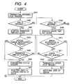
- Fig. 4 is a flow chart illustrating an example of the procedure to be executed by PC 10 and DVC 20 when a user supplies the DV control program 107 with a forward play instruction.
- Step S401 In accordance with a user instruction, the DV control program 107 supplies the USB interface unit 101 with a forward play request (a request for changing the current status of DVC 20 to a play state and transmitting digital video data reproduced from the recording medium 203 to PC 10 via the isochronous pipe 32).
- the USB interface unit 101 transmits the forward play request to DVC 20 via the control pipe 31.
- the USB interface unit 204 receives the forward play request from PC 10 via the control pipe 31 and supplies the received forward play request to the control unit 205. In accordance with the forward play request, the control unit 205 judges whether the status of DVC 10 can be changed to the play state. If the status can be changed to the play state (or if the status is already in the play state), the control unit 205 supplies the USB interface unit 204 with an ACK, whereas if the status of DVC 10 cannot be changed to the play state, the control unit 205 supplies the USB interface unit 204 with a STALL. The USB interface 204 transmits the ACK or STALL to PC 10 via the control pipe 31.
- Step S402 The DV control program 107 judges whether the USB interface unit 101 receives the ACK via the control pipe 31. If the USB interface unit 204 receives the ACK, the flow advances to Step S403, whereas if the USB interface unit 204 cannot receive the ACK, the flow advances to Step S408.
- Step S403 The DV control program 107 starts counting the transport time-out (in present embodiment, the transport time-out is assumed to be five seconds).
- the transport time-out can be acquired from the above-described wTransportTimeout field.
- Step S404 The DV control program 107 judges whether the USB interface unit 101 receives the status change notification (information on a current status change of DVC 20 to be notified to PC 10) via the interrupt pipe 33. If the USB interface unit 101 receives the status change notification, the flow advances to Step S406, whereas if the USB interface unit 101 cannot receive the status change notification by any reason, the flow advances to Step S405.
- Step S405 The DV control program 107 judges whether the transport time-out elapses. If the transport time-out elapses, the flow advances to Step S406, whereas if the transport time-out does not elapse, the flow returns to Step S404.
- Step S406 If the status change notification is received before the lapse of the transport time-out or if the status change notification cannot be received before the lapse of the transport time-out, the DV control program 107 supplies the USB interface unit 101 with a status request (a request for the status information representative of the current status of DVC 20). The USB interface unit 101 transmits the status request to DVC 20 via the control pipe 31.
- the USB interface unit 204 receives the status request from PC 10 via the control pipe 31 and supplies the received status request to the control unit 205.
- the control unit 205 supplies the status information to the USB interface unit 204.
- the USB interface unit 204 transmits the status information to PC 10 via the control pipe 31.
- Step S407 The DV control program 107 analyzes the status information supplied from DVC 20 to judge the current status of DVC 20. In order to notify the user of the current status of DVC 20, the DV control program 107 displays the information (constituted of icons, characters or the like) representative of the current status of DVC 20 on the display unit 103.
- Step S408 The DV control program 107 judges whether the USB interface unit 101 receives the STALL from DVC 20 via the control pipe 31. If the USB interface unit 204 receives the STALL, the flow advances to Step S409.
- Step S409 The DV control program 107 starts counting the error time-out (in present embodiment, the error time-out is assumed to be one second).
- the error time-out can be acquired from the above-described wErrorTimeout field.
- Step S410 The DV control program 107 judges whether the USB interface unit 101 receives the error notification (information on an error occurrence at DVC 20 to be notified to PC 10) via the interrupt pipe 33. If the USB interface unit 101 receives the error notification, the flow advances to Step S412, whereas if the USB interface unit 101 cannot receive the error notification by any reason, the flow advances to Step S411.
- Step S411 The DV control program 107 judges whether the error time-out elapses. If the error time-out elapses, the flow advances to Step S412, whereas if the error time-out does not elapse, the flow returns to Step S410.
- Step S412 If the error notification is received before the lapse of the error time-out or if the error notification is not received before the lapse of the error time-out, the DV control program 107 supplies the USB interface unit 101 with an error code request (a request for an error code representative of the cause of an error occurred at DVC 20). The USB interface unit 101 transmits the error code request to DVC 20 via the control pipe 31.
- an error code request a request for an error code representative of the cause of an error occurred at DVC 20.
- the USB interface unit 204 receives the error code request from PC 10 via the control pipe 31 and supplies the received error code to the control unit 205.
- the control unit 205 supplies the USB interface unit 204 with an error code.
- the USB interface unit 204 transmits the error code to PC 10 via the control pipe 31.
- Step S413 The DV control program 107 analyzes the error code supplied from DVC 20 to identify the cause of the error. In order to notify the user of the error cause, the DV control program 107 displays the information representative of the error cause on the display unit 103.
- the status request can be transmitted to DVC 20 so that it is possible to reliably know whether the status of a digital video apparatus changes to the predetermined status.
- the error request can be transmitted to DVC 20 so that it is possible to reliably notify the reason why the status of the digital video apparatus is unable to be changed to a predetermined status.
- the status time-out can be notified to the DV control program 107 by using the interface descriptor. Therefore, even if the status change notification cannot be transmitted to PC 10 by any reason, the status request can be transmitted to the DV control program 107 at the optimum timing. Accordingly, the DV control program 107 can notify the user of the current status of DVC 20.
- the error time-out can be notified to the DV control program 107 by using the interface descriptor. Therefore, even if the error notification cannot be transmitted to PC 10 by any reason, the error request can be transmitted to the DV control program 107 at the optimum timing. Accordingly, the DV control program 107 can notify the user of the cause of an error occurred at DVC 20.
- the scope of the invention contains also the case wherein software program codes realizing the function of the embodiment described above are supplied to a computer (CPU or MPU) of an apparatus or system connected to various devices realizing the embodiment function, and the computer operates the devices in accordance with the stored programs.
- a computer CPU or MPU
- Transmission media for such program codes may be communication media (wired channels such as optical fibers, radio channels and the like) of a computer network (LAN, WAN such as the Internet, radio communication network or the like) system for supplying program information as carriers of transmission waves.
- LAN local area network
- WAN wide area network
- Means for supplying a computer with such program codes constitute the present invention.
- the storage medium for storing such program codes may be a flexible disk, a hard disk, an optical disk, a magneto-optical disk, a CD-ROM, a magnetic tape, a nonvolatile memory card, a ROM or the like.
- program codes are included as the embodiment of the invention, wherein not only the computer executes the supplied program codes to realize the embodiment function but also the program codes in cooperation with an OS (operating system) running on the computer or with another application or the like realize the embodiment function.
- the present invention is also applicable to a system utilizing extended specifications (inclusive of specifications to be prescribed in the future) of USB1.1 or USB2.0.
Landscapes
- Engineering & Computer Science (AREA)
- Multimedia (AREA)
- Signal Processing (AREA)
- Theoretical Computer Science (AREA)
- Physics & Mathematics (AREA)
- General Engineering & Computer Science (AREA)
- General Physics & Mathematics (AREA)
- Information Transfer Systems (AREA)
- Studio Devices (AREA)
- Details Of Television Systems (AREA)
- Television Signal Processing For Recording (AREA)
Applications Claiming Priority (2)
| Application Number | Priority Date | Filing Date | Title |
|---|---|---|---|
| JP2002363159A JP4343524B2 (ja) | 2002-12-13 | 2002-12-13 | 制御装置およびデジタルビデオ装置 |
| EP03257835.3A EP1429234B1 (de) | 2002-12-13 | 2003-12-12 | Steuervorrichtung und zugehöriges Verfahren |
Related Parent Applications (1)
| Application Number | Title | Priority Date | Filing Date |
|---|---|---|---|
| EP03257835.3 Division | 2003-12-12 |
Publications (3)
| Publication Number | Publication Date |
|---|---|
| EP2320301A2 true EP2320301A2 (de) | 2011-05-11 |
| EP2320301A3 EP2320301A3 (de) | 2011-12-21 |
| EP2320301B1 EP2320301B1 (de) | 2013-02-20 |
Family
ID=32322147
Family Applications (2)
| Application Number | Title | Priority Date | Filing Date |
|---|---|---|---|
| EP11154954A Expired - Lifetime EP2320301B1 (de) | 2002-12-13 | 2003-12-12 | Steuervorrichtung und zugehöriges Verfahren |
| EP03257835.3A Expired - Lifetime EP1429234B1 (de) | 2002-12-13 | 2003-12-12 | Steuervorrichtung und zugehöriges Verfahren |
Family Applications After (1)
| Application Number | Title | Priority Date | Filing Date |
|---|---|---|---|
| EP03257835.3A Expired - Lifetime EP1429234B1 (de) | 2002-12-13 | 2003-12-12 | Steuervorrichtung und zugehöriges Verfahren |
Country Status (5)
| Country | Link |
|---|---|
| US (2) | US7305496B2 (de) |
| EP (2) | EP2320301B1 (de) |
| JP (1) | JP4343524B2 (de) |
| KR (1) | KR100719468B1 (de) |
| CN (2) | CN100487682C (de) |
Families Citing this family (11)
| Publication number | Priority date | Publication date | Assignee | Title |
|---|---|---|---|---|
| JP2004179688A (ja) * | 2002-11-22 | 2004-06-24 | Canon Inc | 再生装置および記録装置 |
| JP4343524B2 (ja) * | 2002-12-13 | 2009-10-14 | キヤノン株式会社 | 制御装置およびデジタルビデオ装置 |
| JP2005176233A (ja) * | 2003-12-15 | 2005-06-30 | Canon Inc | 通信装置及び通信システム |
| JP4695965B2 (ja) * | 2005-11-15 | 2011-06-08 | キヤノン株式会社 | 映像記録装置及びプログラム |
| US7657684B2 (en) * | 2006-04-28 | 2010-02-02 | Qualcomm Incorporated | USB interrupt endpoint sharing |
| US8046524B2 (en) * | 2007-08-08 | 2011-10-25 | Sandisk Technologies Inc. | Managing processing delays in an isochronous system |
| JP5075032B2 (ja) | 2008-06-30 | 2012-11-14 | キヤノン株式会社 | 通信装置及び通信方法 |
| JP5171436B2 (ja) * | 2008-06-30 | 2013-03-27 | キヤノン株式会社 | 通信装置、データ通信システム、通信装置の制御方法及びプログラム |
| US8055784B2 (en) * | 2008-07-07 | 2011-11-08 | Disney Enterprises, Inc. | Content navigation module for managing delivery of content to computing devices and method therefor |
| US8364863B2 (en) * | 2008-07-11 | 2013-01-29 | Intel Corporation | Method and apparatus for universal serial bus (USB) command queuing |
| JP5131243B2 (ja) * | 2009-05-11 | 2013-01-30 | 富士通株式会社 | 伝送装置及び伝送装置の休止方法 |
Family Cites Families (23)
| Publication number | Priority date | Publication date | Assignee | Title |
|---|---|---|---|---|
| US2003A (en) * | 1841-03-12 | Improvement in horizontal windivhlls | ||
| EP0712256B1 (de) * | 1994-11-14 | 2000-04-12 | Canon Kabushiki Kaisha | Aufnahme-/Wiedergabeanlage |
| KR100206461B1 (ko) * | 1995-11-24 | 1999-07-01 | 윤종용 | 프로세스 관리의 구현 및 가시화 방법 |
| US6219736B1 (en) * | 1997-04-24 | 2001-04-17 | Edwin E. Klingman | Universal serial bus (USB) RAM architecture for use with microcomputers via an interface optimized for integrated services device network (ISDN) |
| US6307974B1 (en) * | 1997-06-23 | 2001-10-23 | Canon Kabushika Kaisha | Image processing apparatus, system, and method with adaptive transfer |
| KR19990012591A (ko) * | 1997-07-30 | 1999-02-25 | 이대원 | 컴퓨터로 제어 가능한 디지탈 스틸 카메라 |
| US6072542A (en) | 1997-11-25 | 2000-06-06 | Fuji Xerox Co., Ltd. | Automatic video segmentation using hidden markov model |
| JPH11266383A (ja) | 1998-03-18 | 1999-09-28 | Minolta Co Ltd | デジタルカメラシステム |
| US20010001563A1 (en) * | 1998-05-18 | 2001-05-24 | Edward P. Tomaszewski | Method and apparatus to control the behavior of a digital camera by detecting connectivity to a universal serial bus |
| US6717694B1 (en) * | 1998-07-31 | 2004-04-06 | Canon Kabushiki Kaisha | Data transmission apparatus, system and method, and recording medium |
| JP3943722B2 (ja) | 1998-08-04 | 2007-07-11 | キヤノン株式会社 | データ転送装置、データ転送システムおよびその方法、画像処理装置、並びに、記録媒体 |
| US6311294B1 (en) * | 1998-10-20 | 2001-10-30 | Cypress Semiconductor Corp. | Device and method for efficient bulk data retrieval using a universal serial bus |
| US6389029B1 (en) * | 1998-11-10 | 2002-05-14 | Nortel Networks Limited | Local area network incorporating universal serial bus protocol |
| AU4501200A (en) * | 1999-04-30 | 2000-11-17 | Daniel Kelvin Jackson | Method and apparatus for extending communications over usb |
| JP4499862B2 (ja) | 2000-01-20 | 2010-07-07 | セイコーインスツル株式会社 | Usbインタフェースを有するプリンタの状態検出方法及び該方法を用いたプリントシステム |
| US6735658B1 (en) * | 2000-10-06 | 2004-05-11 | Clearcube Technology, Inc. | System and method for combining computer video and remote universal serial bus in an extended cable |
| US6718412B2 (en) * | 2000-12-14 | 2004-04-06 | Agilent Technologies, Inc. | Apparatus and method for universal serial bus communications |
| JP2002232759A (ja) | 2001-01-31 | 2002-08-16 | Fuji Photo Film Co Ltd | ディジタル・カメラおよびその動作制御方法 |
| EP1229720A3 (de) | 2001-01-31 | 2004-04-14 | Fuji Photo Film Co., Ltd. | Digitale Kamera und Verfahren zur deren Steuerung |
| US7190477B2 (en) * | 2001-02-22 | 2007-03-13 | Sharp Laboratories Of America, Inc. | System and method for managing and processing a print job using print job tickets |
| JP2003209783A (ja) | 2002-01-15 | 2003-07-25 | Canon Inc | ファイル送信装置およびファイル送信方法 |
| JP2004179688A (ja) | 2002-11-22 | 2004-06-24 | Canon Inc | 再生装置および記録装置 |
| JP4343524B2 (ja) * | 2002-12-13 | 2009-10-14 | キヤノン株式会社 | 制御装置およびデジタルビデオ装置 |
-
2002
- 2002-12-13 JP JP2002363159A patent/JP4343524B2/ja not_active Expired - Fee Related
-
2003
- 2003-12-11 KR KR1020030090009A patent/KR100719468B1/ko not_active Expired - Fee Related
- 2003-12-12 US US10/733,362 patent/US7305496B2/en not_active Expired - Fee Related
- 2003-12-12 EP EP11154954A patent/EP2320301B1/de not_active Expired - Lifetime
- 2003-12-12 CN CNB2003101185327A patent/CN100487682C/zh not_active Expired - Fee Related
- 2003-12-12 CN CN2008101457536A patent/CN101335860B/zh not_active Expired - Fee Related
- 2003-12-12 EP EP03257835.3A patent/EP1429234B1/de not_active Expired - Lifetime
-
2007
- 2007-10-30 US US11/928,137 patent/US7577768B2/en not_active Expired - Fee Related
Non-Patent Citations (1)
| Title |
|---|
| None |
Also Published As
| Publication number | Publication date |
|---|---|
| US20040120691A1 (en) | 2004-06-24 |
| JP2004194257A (ja) | 2004-07-08 |
| EP2320301A3 (de) | 2011-12-21 |
| EP1429234A3 (de) | 2008-05-21 |
| CN101335860A (zh) | 2008-12-31 |
| JP4343524B2 (ja) | 2009-10-14 |
| US7577768B2 (en) | 2009-08-18 |
| KR100719468B1 (ko) | 2007-05-17 |
| KR20040053800A (ko) | 2004-06-24 |
| CN1519733A (zh) | 2004-08-11 |
| CN101335860B (zh) | 2011-09-14 |
| US7305496B2 (en) | 2007-12-04 |
| EP1429234A2 (de) | 2004-06-16 |
| EP1429234B1 (de) | 2013-04-17 |
| US20080065791A1 (en) | 2008-03-13 |
| CN100487682C (zh) | 2009-05-13 |
| EP2320301B1 (de) | 2013-02-20 |
Similar Documents
| Publication | Publication Date | Title |
|---|---|---|
| US7577768B2 (en) | Control apparatus and method thereof | |
| JP3565686B2 (ja) | コンピュータの記憶装置及び変換システム | |
| TWI296083B (en) | Communication controller, host-side controller, communication system, usb system, communication equipment, communication method, packet-based communication method, packet-based communication program, and storage medium | |
| US8046517B2 (en) | Data processing method and device for inputting data to pieces of digital equipment | |
| US6690648B2 (en) | Data communication apparatus, method, and system utilizing reception capability information of a destination node | |
| US7505461B2 (en) | Data transfer control device, electronic instrument, and data transfer control method | |
| US7102671B1 (en) | Enhanced compact flash memory card | |
| US7469304B2 (en) | Data transfer control device, electronic equipment, and method for a data transfer through a bus, the data transfer control device including a register and a packet buffer that are commonly used during a host operation and a peripheral operation | |
| US20040057448A1 (en) | Information processing system, information processing apparatus, and information processing method | |
| JP2001067156A (ja) | コンピュータ周辺機器及びその制御方法、撮像装置並びに記憶媒体 | |
| KR20040041623A (ko) | 버스 시스템 및 버스 인터페이스 | |
| US6058440A (en) | Programmable and adaptive resource allocation device and resource use recorder | |
| KR20040043198A (ko) | 버스 시스템 및 버스 인터페이스 | |
| US20100106869A1 (en) | USB Storage Device and Interface Circuit Thereof | |
| JP2008287578A (ja) | メモリコントローラ、情報処理装置及び電子機器 | |
| JP2001337911A (ja) | Usb−atapiインターフェイスシステムとこれに用いるatapi−usb変換機器 | |
| JP2005309511A (ja) | 情報処理装置、ステータス取得方法、及びプログラム | |
| US20060156348A1 (en) | Control apparatus and method | |
| JP2010015429A (ja) | 記憶デバイスコントローラ、情報処理装置及び電子機器 | |
| JP2000049808A (ja) | 赤外線通信機能を有する外部記憶装置、データ処理装置および通信システム | |
| JPH10222252A (ja) | 情報処理装置およびその周辺機器の初期化方法 | |
| JP2003037596A (ja) | 通信装置及び通信方法 | |
| JPH06161667A (ja) | ディスク装置 | |
| JP2010015428A (ja) | 記憶デバイスコントローラ、情報処理装置、電子機器及び記憶デバイスのビジー検出方法 |
Legal Events
| Date | Code | Title | Description |
|---|---|---|---|
| PUAI | Public reference made under article 153(3) epc to a published international application that has entered the european phase |
Free format text: ORIGINAL CODE: 0009012 |
|
| AC | Divisional application: reference to earlier application |
Ref document number: 1429234 Country of ref document: EP Kind code of ref document: P |
|
| AK | Designated contracting states |
Kind code of ref document: A2 Designated state(s): DE FR GB IT NL |
|
| PUAL | Search report despatched |
Free format text: ORIGINAL CODE: 0009013 |
|
| AK | Designated contracting states |
Kind code of ref document: A3 Designated state(s): DE FR GB IT NL |
|
| RIC1 | Information provided on ipc code assigned before grant |
Ipc: H04N 5/765 20060101ALI20111114BHEP Ipc: G06F 3/00 20060101AFI20111114BHEP |
|
| REG | Reference to a national code |
Ref country code: DE Ref legal event code: R079 Ref document number: 60343340 Country of ref document: DE Free format text: PREVIOUS MAIN CLASS: G06F0003000000 Ipc: H04N0005765000 |
|
| 17P | Request for examination filed |
Effective date: 20120621 |
|
| RIC1 | Information provided on ipc code assigned before grant |
Ipc: H04N 5/765 20060101AFI20120725BHEP |
|
| GRAP | Despatch of communication of intention to grant a patent |
Free format text: ORIGINAL CODE: EPIDOSNIGR1 |
|
| GRAS | Grant fee paid |
Free format text: ORIGINAL CODE: EPIDOSNIGR3 |
|
| GRAA | (expected) grant |
Free format text: ORIGINAL CODE: 0009210 |
|
| AC | Divisional application: reference to earlier application |
Ref document number: 1429234 Country of ref document: EP Kind code of ref document: P |
|
| AK | Designated contracting states |
Kind code of ref document: B1 Designated state(s): DE FR GB IT NL |
|
| REG | Reference to a national code |
Ref country code: GB Ref legal event code: FG4D |
|
| REG | Reference to a national code |
Ref country code: DE Ref legal event code: R096 Ref document number: 60343340 Country of ref document: DE Effective date: 20130418 |
|
| REG | Reference to a national code |
Ref country code: NL Ref legal event code: VDEP Effective date: 20130220 |
|
| PG25 | Lapsed in a contracting state [announced via postgrant information from national office to epo] |
Ref country code: NL Free format text: LAPSE BECAUSE OF FAILURE TO SUBMIT A TRANSLATION OF THE DESCRIPTION OR TO PAY THE FEE WITHIN THE PRESCRIBED TIME-LIMIT Effective date: 20130220 |
|
| PLBE | No opposition filed within time limit |
Free format text: ORIGINAL CODE: 0009261 |
|
| STAA | Information on the status of an ep patent application or granted ep patent |
Free format text: STATUS: NO OPPOSITION FILED WITHIN TIME LIMIT |
|
| PG25 | Lapsed in a contracting state [announced via postgrant information from national office to epo] |
Ref country code: IT Free format text: LAPSE BECAUSE OF FAILURE TO SUBMIT A TRANSLATION OF THE DESCRIPTION OR TO PAY THE FEE WITHIN THE PRESCRIBED TIME-LIMIT Effective date: 20130220 |
|
| 26N | No opposition filed |
Effective date: 20131121 |
|
| REG | Reference to a national code |
Ref country code: DE Ref legal event code: R097 Ref document number: 60343340 Country of ref document: DE Effective date: 20131121 |
|
| REG | Reference to a national code |
Ref country code: FR Ref legal event code: PLFP Year of fee payment: 13 |
|
| REG | Reference to a national code |
Ref country code: FR Ref legal event code: PLFP Year of fee payment: 14 |
|
| PGFP | Annual fee paid to national office [announced via postgrant information from national office to epo] |
Ref country code: FR Payment date: 20161223 Year of fee payment: 14 |
|
| REG | Reference to a national code |
Ref country code: FR Ref legal event code: ST Effective date: 20180831 |
|
| PG25 | Lapsed in a contracting state [announced via postgrant information from national office to epo] |
Ref country code: FR Free format text: LAPSE BECAUSE OF NON-PAYMENT OF DUE FEES Effective date: 20180102 |
|
| PGFP | Annual fee paid to national office [announced via postgrant information from national office to epo] |
Ref country code: GB Payment date: 20191226 Year of fee payment: 17 Ref country code: DE Payment date: 20200227 Year of fee payment: 17 |
|
| REG | Reference to a national code |
Ref country code: DE Ref legal event code: R119 Ref document number: 60343340 Country of ref document: DE |
|
| GBPC | Gb: european patent ceased through non-payment of renewal fee |
Effective date: 20201212 |
|
| PG25 | Lapsed in a contracting state [announced via postgrant information from national office to epo] |
Ref country code: DE Free format text: LAPSE BECAUSE OF NON-PAYMENT OF DUE FEES Effective date: 20210701 Ref country code: GB Free format text: LAPSE BECAUSE OF NON-PAYMENT OF DUE FEES Effective date: 20201212 |